1
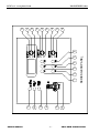
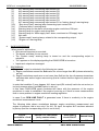
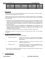
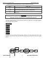
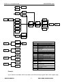
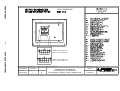
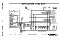
ELECTRONIC PANEL
FOR ALARMS, SECURITIES AND
ENGINE CONTROL
CM30 GE3B
Series
USER’S MANUAL
PINE s.r.l. www.pinesrl.com
MANGE3BEVA.doc
INDEX
1.INTRODUCTION ....................................................................................................................................... 3
2.INSTALLATION......................................................................................................................................... 3
3.GENERAL FEATURES ............................................................................................................................. 4
4.KEYS FUNCTIONS.................................................................................................................................... 4
5.WARNING LAMPS .................................................................................................................................... 4
6.PANEL SWITCH-ON ................................................................................................................................. 5
7.ENGINE RUN.............................................................................................................................................. 5
8.ENGINE STOP ............................................................................................................................................ 6
9.OUTPUTS (FOR REMOTE CONTROL) ................................................................................................ 6
10.ALARM CONDITONS ............................................................................................................................. 6
11.ALARM CIRCUITS FAULT ................................................................................................................... 7
12.PANEL SET-UP......................................................................................................................................... 7
13.ENGINE PLANT ANOMALIES ........................................................................................................... 10
14.CONFORMITY DECLARATION ........................................................................................................ 11
15.TECHNICAL SPECIFICATIONS ........................................................................................................ 11
USER’S MANUAL
-1-
CM30 GE3B ALARM PANEL
3
5
2
4
1
-2-
10
UP
9
8
21
20
7
USER’S MANUAL
SERIES GE3B PANEL
6
19
13
18
SEL
17
12
SEL
16
15
MANGE3BEVA.doc
SEL
11
14
PINE s.r.l. www.pinesrl.com
CM30 GE3B ALARM PANEL
PINE s.r.l. www.pinesrl.com
1.
MANGE3BEVA.doc
INTRODUCTION
CM30-GE3B is an engine control panel for alarms and securities management, controlled by
a microprocessor. It is particularly meant for combustion engines and disposes of inputs and
outputs for interfacing to the control and monitoring main system.
A polycarbonate front, mounted on an aluminium support, protects control and visualization
part: it describes all the GE30-GE3B functions, can be personalized on demand and realized
in any desired language. The rear is in painted metal and connectors to the plant are of the
type with mechanical block.
All functions performed by CM30-GE3B panel are intuitive and simple: the measurement and
alarm set is also so simple and immediate.
CM30-GE3B deals with seven ON/OFF alarms and a frequency measurement for engine
revolutions.
Alarms are managed according the ISA –1 sequence.
Intervention of each alarm can be delayed up to 240 seconds in order to avoid false
signallings or commutations.
RPM input can be used to influence alarms according the engine condition and to generate
the overspeed alarm (or security).
Each alarm can be separately inhibited when the engine is off or during ignition: these
conditions are detected through the engine revolutions input.
A connection continuity (or short circuit) control can be activated on each alarm input
generating an alarm in case of fault.
Each alarm can perform the engine stop if it is used as a security.
“Inhibited securities”, S5 input, allows deactivating the engine stop function for all the alarms
apart from the overspeed alarm.
CM30-GE3B has two supply input: a main supply and a secondary one with optional battery
charge. In case of a main supply fault an alarm will be generated (16); this alarm cannot be
used as security.
2.
INSTALLATION
CM30-GE3B series engine control panels can be placed on the ship’s pilot bridge or on a
board. Cutting for a proper assembly is shown in D4 drawing.
ALARMS – FAULTS -AUTOMATIC STOP TEST
It is possible to test the correct working of alarms (inactive when engine is regularly running)
by simulating their activation. Regarding securities, test their intervention simulating an alarm
both when engine is off and running.
In order to simulate faults at N.O. contacts it is sufficient to keep the connection wire
USER’S MANUAL
-3-
CM30 GE3B ALARM PANEL
PINE s.r.l. www.pinesrl.com
MANGE3BEVA.doc
unconnected.
You need an engine revolutions simulator to test the overspeed alarm condition; otherwise it
is sufficient to decrease the alarm thresholds by set-up in order to generate an alarm at a low
rate value. After test restore alarm thresholds at the original value.
If dual supply is present unconnect the main supply in order to test the main supply fault
alarm.
Remember that each alarm will be signalled with the set delay time.
NOTE: it is advisable to test all alarms.
3.
GENERAL FEATURES
•
•
•
•
•
•
•
•
•
•
•
•
4.
15 alarm and fault or other signallings warning lamps;
Alarms acknowledgment/silencing key;
Lamp test ( by simultaneously pressing (9) and (10) keys;
Dimmerable brightness;
7 inputs for alarms/securities with continuity (or short circuit) control;
1 frequency input for engine revolutions measurement with continuity control;
“Electrostop connection continuity control” input
Input for remote silencing (remote muting);
Management of the following command inputs:
“Connected/unconnected securities” input
“Remote engine stop command” input
Outputs:
“Engine run” output
“Common failure” output
“System ready” output
“Engine stop” output
“Buzzer” output
“Alternator excitation (D+)” (if AL7 not used)
Main and secondary supplies: from 12 up to 24Vcc (to be selected by set-up);
Size: 162 x 134 x 100 mm;
KEYS FUNCTIONS
(11)
used in set-up.
(12)
keep pressed to display engine revolutions (x 10) / used in set-up.
(13)
used in set-up.
(9)
used to decrease the displays and warning lamps brightness / used in set-up
(10)
used to increase the displays and warning lamps brightness / used in set-up.
(9) e (10)
perform the lamp test if simultaneously pressed.
(8)
used as alarm acknowledgment/silencing according to ISA-1 sequence / used in setup.
5.
WARNING LAMPS
USER’S MANUAL
-4-
CM30 GE3B ALARM PANEL
PINE s.r.l. www.pinesrl.com
(1)
(2)
(3)
(4)
(5)
(6)
(7)
(20)
(21)
(14)
(15)
(16)
(17)
(18)
(19)
6.
MANGE3BEVA.doc
AL1 warning lamp concerning input contact R4.
AL2 warning lamp concerning input contact R3.
AL3 warning lamp concerning input contact S6.
AL4 warning lamp concerning input contact R7.
AL5 warning lamp concerning input contact R6.
AL6 warning lamp concerning input contact S3.
AL7 warning lamp concerning input contact R1 or “battery charge” warning lamp.
“Stop circuit fault” warning lamp concerning input contact S8.
“Common failure” warning lamp.
Warning lamp for the alarm concerning engine revolutions, R9 input.
Warning lamp for engine revolutions fault.
Warning lamp for “Main supply fault” alarm, monitored on R2 supply input.
Not used.
“System ready” warning lamp, related to the corresponding output.
“Engine run” warning lamp.
PANEL SWITCH-ON
When panel is switched on:
• One-second lamp-test is executed;
• The buzzer activates for one second;
• The “System ready” warning lamp is turned on and the corresponding output is
activated;
• “On” appears on the display signalling that CM30-GE3B is turned-on.
• Inputs and outputs are managed.
7.
ENGINE RUN
“Engine run” output is activated in the following two cases:
1) Engine revolutions exceed the SoA value for a time longer than tEr (values selected by
set-up);
2) Engine revolutions equal zero or are lower than SoA but the low oil pressure transducer
switches state as the engine was running (that is it detect that the engine oil pressure is
risen up).
In order that condition 2) may happen, AL1 alarm input (R4 contact) had to be set as low (or
too low) pressure alarm (see ALP option in set-up).
In this case CM30-GE3B panel correlates this alarm with the presence of the engine
revolutions in order to estabilish if the engine is running or if there is some measurements
fault or some problem in engine revolutions reading regulation.
In case 2) an RPM LINE FAULT is generated even if there is continuity in the engine
revolutions measurement circuit.
The following table shows correlations between engine revolutions measurement and
engine oil pressure; this is true only if for AL1, P4 input, the option ALP has been selected
by set-up (and the corresponding circuit is not in fault).
Engine
revolutions > SoA
ENGINE OIL PRESSURE
(as by contact alarm)
RPM reading
circuit FAULT
ENGINE RUN
RPM = 0
LOW
NO
NO
USER’S MANUAL
-5-
CM30 GE3B ALARM PANEL
PINE s.r.l. www.pinesrl.com
NO
NO
YES
YES
8.
MANGE3BEVA.doc
LOW
HIGH
LOW
HIGH
YES
YES
NO
NO
NO
YES
YES
YES
ENGINE STOP
In order to execute engine stop CM30-GE3B closes the circuit tied up to S1 and S2 contacts;
a self restoring fuse protects the line by inside.
“Engine stop continuity circuit” must be directly connected to electro-stop (or to the possible
re-launching relay) present on the engine. In case of continuity fault a stop circuit fault alarm
will be generated.
•
Engine stop has to be performed by activating “remote engine stop command” input (R8
contact) or it may happen because of any security intervention (if it is enabled). In both
cases a possible running ignition phase is immediately stopped and the stop contacts are
closed until the engine is motionless or however for a maximum stop time tAA that may
be select by set-up.
By set-up engine stop can be programmed on a threshold that can be selected on the
engine revolutions measurement (overspeed). If CM30-GE3B is programmed with the
overspeed security threshold, engine stop will be performed even in presence of the
“deactivated securities” comand.
If any alarm is programmed as security, its activation will cause an engine stop.
•
•
“Deactivated securities” S5 input works only with alarm/security inputs, not with engine
overspeed.
9.
OUTPUTS (FOR REMOTE CONTROL)
CM30-GE3B disposes of the following output signals:
•
System ready (S11):
indicates that the panel is supplied and works properly.
Lacking of this output corresponds with the CM30-GE3B
fault signalling.
•
Common failure (S10):
enabled by any alarm (or security) or any fault at alarm
and stop connection circuit.
•
Engine run (S7):
indicates that the engine is running at a speed higher than
a pre-selected threshold. It is enabled even if a “high
engine oil pressure” signal is present.
These active low outputs are protected from short circuit and provide the necessary current
to excite a relay (see technical notes).
10.
ALARM CONDITONS
USER’S MANUAL
-6-
CM30 GE3B ALARM PANEL
PINE s.r.l. www.pinesrl.com
MANGE3BEVA.doc
At “System ready”, alarms are managed according to ISA-1 sequence.
ON/OFF alarms come from transmitters with preset intervention thresholds and they can be
N.O. or N.C. contacts.
Alarms input are active low so one of the two contacts of each transmitter has to be
connected to the CM30-GE3B negative supply.
Connection continuity control can be enabled if contacts are of N.O. type.
Connection short circuit control can be enabled if contacts are of N.C. type.
See CM30-GE3B set-up for available options.
Regarding to ON/OFF alarms, available option are:
GoF/Gon
Alarm is always enabled (GoF) or only if engine is running (Gon).
AoF/Aon
automatic stop off/on.
rit
alarm delay; alarm contact must remain ON for the same time as rit or longer,
in order to be recognized as alarm condition.
Available options for overspeed alarm are:
So1
AoF/Aon
rit
Alarm threshold
- alarm is generated if measurement exceeds the threshold value.
Automatic stop off/on.
If alarm input remains activated for a time (in seconds) longer than rit, alarm
condition will be recognized and managed.
“Main supply fault” alarm is activated if the main supply isn’t present. This alarm can be
managed only in presence of secondary supply.
11.
ALARM CIRCUITS FAULT
At “System Ready” the circuit faults are managed as alarms and so according to ISA-1
sequence.
An alarm for circuit fault is signalled by the alarm itself and by the “Common Failure” warning
lamp turning on. In some cases the fault is “deduced” by an irregular behaviour of correlated
measurements (see “ENGINE RUN” chapter”).
• Regarding alarms generated by ON/OFF contacts, the fault will be signalled in case of
interruption of the connection circuit for N.O. contacts, and in case of short circuit of the
connection circuit for N.C. contacts (see ON/OFF alarm selection code Table).
• Regarding the overspeed alarm, the fault will be signalled in case of interruption of the
connection circuit and in the case 2) described in “ENGINE RUN” chapter.
12.
PANEL SET-UP
Set-up allows to:
• Adjust the parameters useful for the alarms and signals generation;
• Adjust the panels to the engine specifications;
USER’S MANUAL
-7-
CM30 GE3B ALARM PANEL
PINE s.r.l. www.pinesrl.com
•
MANGE3BEVA.doc
Regulate and tare the parameters for a correct transducers working.
KEYS
FUNCTION
(11)
Choose measurements to be changed / Confirm new calibrations
(9) (10)
Move among the main-menu rows / Change values
Go to main-menu / Exit from set-up storing new data if user is in
main-menu
(8)
WARNING
IF DURING SET-UP NO KEY IS PRESSED WITHIN 60 SECONDS, AUTOMATIC EXIT
FROM SET-UP WILL OCCUR AND ALL CHANGES WILL BE LOST.
To enter set-up press key (11) until buzzer produces a beep and in the display appears
one of the main menu options.
MAIN MENU
P
t
r n
A
r
O P 1
O P 2
O P 3
In regard to set-up scheme (following page), with key (11) user moves from left to right,
while with keys (9) and (10) he moves in the vertical sense; to return to main menu press
key (8).
ESC
rPn
AoF
S o1
Val.
SOA
USER’S MANUAL
rit
Val.
Aon
-8-
CM30 GE3B ALARM PANEL
PINE s.r.l. www.pinesrl.com
t AA
MANGE3BEVA.doc
Val.
tEr
A LP
A L1
A LL
Prn
SEt
A L2
noS
A L3
GoF
AoF
noC
rit
A L4
Gon
Aon
A L5
Val.
ncS
ncC
A L6
ALb
A L7
A LL
rA P
tAr
LEGEND
Val.
Prn
tAr
OP1/2/3
SEt
rPn
ron/roF
ron
Lon/oF
OP 1
12/24
rPn
tAA
tEr
rof
SoA
L on
ALX
rAP
ALP
ALL
ALb
OP 2
L oF
GoF/Gon
12
Aon/AoF
OP 3
noS/C
24
ncS/C
rit
So1
Parameters setting
Engine revolutions reading adjustment
Options
Alarms settings
Activated/deactivated engine revolutions
measurement
Activated/deactivated brightness memory
(see notes)
12Vcc o 24Vcc supply voltage
Engine revolutions; engine revolutions x 10
Maximum engine stop time
Engine run delay (see notes)
Engine revolutions threshold to declare
engine running
Alarm 1,2, … (for AL7 see notes)
Pulses/revolutions ratio (see notes)
Low oil pressure alarm
Generic alarm
Battery charge input
Alarm influenced by engine revolutions
presence
Activated/deactivated engine stop
Alarm contact normally open with/without
open line control
Alarm contact normally closed with/without
short circuit line control
Alarm delay
Overspeed threshold
Example
If you want to set alarm AL2 as an alarm not influenced by engine state, with engine stop,
USER’S MANUAL
-9-
CM30 GE3B ALARM PANEL
PINE s.r.l. www.pinesrl.com
MANGE3BEVA.doc
normally open contact type with line continuity control, 5 seconds delay:
- Enter set-up by keeping key (11) pressed
- If Prn doesn’t appear at once press one or more times key (9) or (10) until Prn appears on
the display; press key (11): Set is displayed. Press key (11) again
- press one or more times key (9) or (10) until AL2 appears on the display; press key (11)
- press one or more times key (9) or (10) until GoF (alarm is independent from engine
running) appears on the display; press key (11)
- press one or more times key (9) or (10) until Aon (alarm causes the engine stop) appears
on the display; press key (11)
- press one or more times key (9) or (10) until noC (normally open contact with line
continuity control) appears on the display; press key (11): rit appears; Press key (11) again
- set delay to 5 seconds – 005 – using key (9) and (10)
- press key (11) if you want remain in set-up and change other alarm parameters or
- press key (8) one or more times to return back on the menu; if appears Prn and you press
key (8) again you exit from set-up in a right manner.
If you don’t exit set-up properly by pressing key (8) more times, performed changes will be
lost and the previous ones will remain in memory.
NOTES:
1 - Ratio r A
P means number of pulses for every engine revolution.
If ratio is known, select rAP and set it pressing keys (9) and (10).
If ratio is unknown, select the visualization of engine revolutions rPn pressing key (9) or (10)
and, once pressed key (11), set the same value read by a precision revolutions counter
using keys (9) and (10). Repeat this operation to low, medium and high rate for a more
accurate regulation.
Note: If panel dispose of a PINE magnetic pick-up adapter, Ratio (rAP) to be set is obtained
dividing by 16 the number of crown wheel cogs.
2 – Engine is declared running if engine revolutions exceed SoA for a time longer than
t E r.
3 – At panel turning on the display brightness will be at maximum if the L o F option is
set. Instead if the L o n option is set, display brightness will be as it was set before last
turning off.
4 – Remember that the number read during regulation has to be multiplied by 10.
5 – If AL7 is set as battery charge warning lamp, it will not be managed as alarm anymore.
13.
ENGINE PLANT ANOMALIES
At turning on and during normal working CM30-GE3B checks set-up settings stored in an
USER’S MANUAL
- 10 -
CM30 GE3B ALARM PANEL
PINE s.r.l. www.pinesrl.com
MANGE3BEVA.doc
internal memory. If the panel works regularly and it is supplied in a right manner, the “System
ready” signal is sent to Remote Control. If “System ready” signalling is lacking and in the first
display row appears “Ed” (data error) followed by a number (indicating the type of internal
memory fault), it means that there is some problem in set-up memory read/write process. In
this case you can try to enter set-up and verify parameters, restoring the changed ones.
Exiting se-up the memory is written again; if “Ed” (data error) appears again it is necessary to
contact CM30-GE3B supplier in order to repair the panel.
If main or secondary supply isn’t present or if there is some panel fault, “System ready”
output will not be activated.
RPM measurement:
• In the case an input has been set as low or too low oil pressure alarm, if engine
revolutions are below the SoA threshold and pressure transducer is not in an alarm
condition, CM30-GE3B will signal an “RPM circuit fault” even if there should be a
pressure transducer fault.
14.
CONFORMITY DECLARATION
Manufactures declares that the engine control panel of series CM30 GE3B is in
conformity at European requirements of electromagnetic compatibility and of
safety with directives 2006/95/EEC (ex 73/23/EEC), 89/336/EEC, 92/31/EEC,
93/68/EEC, 93/97/EEC, EN 60945, and RINA RULES ed. 2007.
15.
TECHNICAL SPECIFICATIONS
MAIN
POWER SUPPLY
USER’S MANUAL
Nominal voltage from 12 up to 24Vcc (min 7 max 35Vcc) with “main supply fault” alarm if:
option 12V, supply below 7V for more than 20 seconds
option 24V, supply below 14V for more than 20 seconds
- 11 -
CM30 GE3B ALARM PANEL
PINE s.r.l. www.pinesrl.com
MANGE3BEVA.doc
SECONDARY
As the main one, without alarm – with recharge circuit if a stop-gap battery is used
POWER CONSUMPTION (no load)
Less than 10 Watt
Polarity inversion, Battery disconnecting extravoltage
(not repetitive).
PROTECTIONS
WORKING TEMPERATURE
-25 +55 °C
STORAGE TEMPERATURE
-30 +80 °C
TEMPERATURE
RELATIVE HUMIDITY
VISUALIZATION
Max 95 %
1 row led display
SIGNALLINGS
WARNING LAMP
7 warning lamps for alarms
Stop line fault
Common failure
ACOUSTIC INDICATION
Buzzer output
Alternator "W" (with 10KΩ resistor in parallel)
FREQUENCY INPUT
PNP PROXIMITY SENSOR
ENGINE REVOLUTIONS with line continuity
control
Pick-up on crown wheel (impedance from
Vout from 3 up to 50Vrms) (with PINE adapter)
1
up
to
20KΩ,
AL1
AL2
INPUTS from N.C. or N.O. type contacts
Open circuit voltage:
5 Vdc
with possible continuity or short circuit
Short circuit voltage: 0-2Vdc - 0,5 mA
control by installing a 10KΩ resistor in
Voltage for continuity/short circuit test, with 10KΩ resistor:
parallel or in series to the contact
AL3
ALARMS
AL4
AL5
AL6
AL7
CONTINUITY TEST ELETTROSTOP CONNECTION LINE
Fault if open circuit
STOP
ACTIVE to positive supply +/- 20% - 5 mA
DEACTIVATED SECURITIES
ACTIVE to positive supply +/- 20% - 5 mA
REMOTE COMANDS INPUTS
REMOTE MUTING INPUT
OUTPUTS
ACTIVE to positive supply +/- 20% - 5 mA
SHORT CIRCUIT
PROTECTED
MEASURE PRECISIONS
ENGINE RPM:
USER’S MANUAL
ENGINE STOP
Positive supply, Imax = 2A
ENGINE RUN
Negative supply, Imax = 300 mA
COMMON FAILURES
Negative supply, Imax = 300 mA
SYSTEM READY
Negative supply, Imax = 300 mA
BUZZER (ACOUSTIC SIGNALLING)
Negative supply, Imax = 300 mA
ALTERNATOR EXCITATION
Positive supply, Imax = 100 mA
10 rpm risolution
± 10 rpm precision
- 12 -
CM30 GE3B ALARM PANEL
2,5 Vdc
PINE s.r.l. www.pinesrl.com
USER’S MANUAL
VISTA POSTERIORE
- 13 10 9 8 7 6
12 11 10 9 8 7
6 5 4 3 2 1
RIF. FILE / FILE REF. :
DSDXG3B01A
CODICE / CODE :
DSDXG3B01A
DATA / DATE :
SCALA / SCALE :
05/07/2007
REV. / REV. :
A
FOGLIO / SHEET :
D1
CONNETTORE S MINIFIT 12p
MINIFIT 12p S CONNECTOR
DESCRIZIONE / DESCRIPTION :
CONNETTORI CENTRALINA
ELETTRONICA DI CONTROLLO
ELECTRONIC CONTROL UNIT CONNECTORS
DISEGNATO / DESIGNED :
DA RE L.
APPROVATO / APPROVED :
PADOAN M.
Chioggia (VE) - Italy
MANGE3BEVA.doc
CM30 GE3B ALARM PANEL
CONNETTORE R MINIFIT 10p
MINIFIT 10p R CONNECTOR
5 4 3 2 1
ALLARME AL7 / CARICA BATT.
R1 ING.
ING. ALLARME AL7 / CARICA BATT.
ALIMENTAZIONE PRINCIPALE
R2 ++ MAIN
POWER SUPPLY
DI ALLARME AL2
R3 INGRESSO
ALARM INPUT AL2
DI ALLARME AL1
R4 INGRESSO
ALARM INPUT AL1
ALIM. PRINCIPALE
R5 PRESENZA
MAIN POWER SUPPLY PRESENT
DI ALLARME AL5
R6 INGRESSO
ALARM INPUT AL5
ARRESTO
ARRESTO
PINE s.r.l. www.pinesrl.com
USER’S MANUAL
CM30 - GE3B
FUSIBILE
FUSE
COMANDI ED USCITE
REMOTI
REMOTE COMMANDS AND
OUTPUTS
DI ALLARME AL4
R7 INGRESSO
ALARM INPUT AL4
IN ALTERNATIVA
IN ALTERNATIVE
ING. "COM. REM. ARR. MOTORE"
R8 "ENG.
STOP REMOTE COM." INPUT
GIRI MOTORE
R9 INGRESSO
ENGINE REVOLUTIONS INPUT
TACITAZ.
MUTING
SICUREZZE DISINSERITE
DEACTIVATED SECURITIES
R10 -- ALIMENTAZIONE
POWER SUPPLY
RELE' STOP AUTOMATICO (NO)
S1 AUTOMATIC STOP RELAY (N.O.)
RELE' STOP AUTOMATICO (C)
S2 AUTOMATIC STOP RELAY (C)
DI ALLARME AL6
S3 INGRESSO
ALARM INPUT AL6
CICALINO (NEGATIVO)
S4 USCITA
BUZZER OUTPUT (NEGATIVE)
DISINSERITE
S5 SICUREZZE
DEACTIVATED SECURITIES
DI ALLARME AL3
S6 INGRESSO
ALARM INPUT AL3
MOTORE IN MOTO
S7 USCITA
ENGINE RUN OUTPUT
CONTINUITA' CIRC. DI ARRESTO
S8 STOP
CIRCUIT CONTINUITY
INGRESSO
TACITAZIONE REMOTA
S9 REMOTE MUTING
INPUT
CUMULATIVO ALLARMI
S10 USCITA
COMMON FAILURE OUTPUT
CM PRONTO
S11 USCITA
SYSTEM READY OUTPUT
ALIMENTAZIONE SECONDARIA
S12 ++ SECONDARY
POWER SUPPLY
MOTORE IN MOTO
ENGINE RUN
R
AL1
R
R
AL2
AL3
R
AL4
R
AL5
R
AL6
R
ARR
AL7
FUSIBILE
FUSE
AVV
ALIMENTAZIONE
SECONDARIA
SECONDARY
POWER SUPPLY
ALIMENTAZIONE
PRINCIPALE
MAIN POWER
SUPPLY
RIF. FILE / FILE REF. :
DSDXG3B02A
CODICE / CODE :
DSDXG3B02A
DESCRIZIONE / DESCRIPTION :
DATA / DATE :
10/07/2007
REV. / REV. :
A
ALLARMI NORMALMENTE APERTI CON
CONTROLLO DI CONTINUITA' (R=10K Ω)
NORMALLY OPEN ALARMS WITH
CONTINUITI CONTROL (R=10K Ω)
FOGLIO / SHEET :
D2
ESEMPIO DI CABLAGGIO
ASSEMBLY EXAMPLE
DISEGNATO / DESIGNED :
DA RE L.
APPROVATO / APPROVED :
PADOAN M.
s.r.l.
Chioggia (VE) - Italy
MANGE3BEVA.doc
CM30 GE3B ALARM PANEL
CM PRONTO
SYSTEM READY
SENSORE GIRI
REVOLUTIONS
TRANSDUCER
- 14 CUMULATIVO ALLARMI
COMMON FAILURES
NORMALLY OPEN ALARM
WITHOUT CONTINUITY CONTROL
ALLARME NORMALMENTE APERTO
CON CONTROLLO DI CONTINUITA'
NORMALLY OPEN ALARM
WITH CONTINUITYCONTROL
10KΩ
INGRESSO GENERICO
GENERIC INPUT
INGRESSO GENERICO
GENERIC INPUT
- ALIMENTAZIONE
- SUPPLY
- ALIMENTAZIONE
- SUPPLY
ALLARME NORMALMENTE CHIUSO
CON CONTROLLO DI CORTOCIRCUITO
NORMALLY CLOSED ALARM WITHOUT
SHORT CIRCUIT CONTROL
NORMALLY CLOSED ALARM WITH
SHORT CIRCUIT CONTROL
- 15 -
ALLARME NORMALMENTE CHIUSO
SENZA CONTROLLO DI CORTOCIRCUITO
10KΩ
- ALIMENTAZIONE
- SUPPLY
RIF. FILE / FILE REF. :
DSDXG3B03A
CODICE / CODE :
DSDXG3B03A
DATA / DATE :
SCALA / SCALE :
14/09/2007
REV. / REV. :
A
FOGLIO / SHEET :
D3
DESCRIZIONE / DESCRIPTION :
SCHEMA DI COLLEGAMENTO DEGLI ALLARMI
ALARMS CONNECTION SCHEME
INGRESSO GENERICO
GENERIC INPUT
- ALIMENTAZIONE
- SUPPLY
DISEGNATO / DESIGNED :
DA RE L.
APPROVATO / APPROVED :
PADOAN M.
Chioggia (VE) - Italy
MANGE3BEVA.doc
CM30 GE3B ALARM PANEL
INGRESSO GENERICO
GENERIC INPUT
PINE s.r.l. www.pinesrl.com
USER’S MANUAL
ALLARME NORMALMENTE APERTO
SENZA CONTROLLO DI CONTINUITA'
150.0
4.0
55.0
20.4
PINE s.r.l. www.pinesrl.com
USER’S MANUAL
162.0
146.8
134.0
122.0
6.0
118.4
- 16 -
FORO ∅ 3,5 mm
SVASATO ∅ 4,5 mm
100.0
RIF. FILE / FILE REF. :
DSDXG3B04A
CODICE / CODE :
DSDXG3B04A
DATA / DATE :
SCALA / SCALE :
11/07/2007
REV. / REV. :
A
FOGLIO / SHEET :
D4
DESCRIZIONE / DESCRIPTION :
DIME DI FORATURA - DIMENSIONI
CUTTING EDGE - SIZE
DISEGNATO / DESIGNED :
DA RE L.
APPROVATO / APPROVED :
PADOAN M.
Chioggia (VE) - Italy
MANGE3BEVA.doc
CM30 GE3B ALARM PANEL
6.0
PINE s.r.l. www.pinesrl.com
MANGE3BEVA.doc
......................................................................................................................................
......................................................................................................................................
......................................................................................................................................
......................................................................................................................................
......................................................................................................................................
......................................................................................................................................
......................................................................................................................................
......................................................................................................................................
......................................................................................................................................
......................................................................................................................................
......................................................................................................................................
......................................................................................................................................
......................................................................................................................................
......................................................................................................................................
......................................................................................................................................
......................................................................................................................................
......................................................................................................................................
......................................................................................................................................
......................................................................................................................................
......................................................................................................................................
......................................................................................................................................
......................................................................................................................................
......................................................................................................................................
......................................................................................................................................
......................................................................................................................................
......................................................................................................................................
......................................................................................................................................
......................................................................................................................................
......................................................................................................................................
......................................................................................................................................
......................................................................................................................................
......................................................................................................................................
......................................................................................................................................
......................................................................................................................................
......................................................................................................................................
SISTEMI ELETTRONICI
Sede legale : Via P. E. Venturini, 56 - 30015 Chioggia (VE) - Italia
Sede operativa : Via D. Schiavo, 181 - 30019 Sottomarina (VE) - Italia
Telefono +39.041.55.44.862 – Tel / Fax +39.041.55.43.194
USER’S MANUAL
- 17 -
CM30 GE3B ALARM PANEL