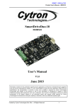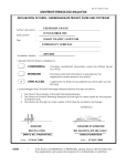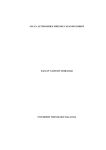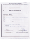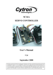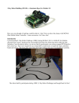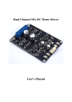
1
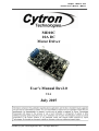
ROBOT . HEAD to TOE Product User’s Manual – MD10C MD10C 10A DC Motor Driver User's Manual Rev2.0 V2.1 July 2015 Created by Cytron Technologies Sdn. Bhd. – All Rights Reserved 1 ROBOT . HEAD to TOE Product User’s Manual – MD10C INDEX 1. Introduction/Overview 3 2. 3. 4. 5. Packing List 4 Board Layout and Specification 5 Dimension 7 Getting Started 8 6. Warranty 9 Created by Cytron Technologies Sdn. Bhd. – All Rights Reserved 2 ROBOT . HEAD to TOE Product User’s Manual – MD10C 1. INTRODUCTION/OVERVIEW MD10C is another version of the MD10B which is designed to drive high current brushed DC motor up to 13A continuously. It offers several enhancements over the MD10B such as support for both lockedantiphase and signmagnitude PWM signal as well as using full solid state components which result in faster response time and eliminate the wear and tear of the mechanical relay. The MD10C has been designed with the capabilities and features of: ● Bidirectional control for 1 brushed DC motor. ● Support motor voltage ranges from 5V to 25V. ● Maximum current up to 13A continuous and 30A peak (10 second). ● 3.3V and 5V logic level input. ● Solid state components provide faster response time and eliminate the wear and tear of mechanical relay. ● Fully NMOS HBridge for better efficiency and no heat sink is required. ● Speed control PWM frequency up to 20KHz (Actual output frequency is same as input frequency). ● Support both lockedantiphase and signmagnitude PWM operation. ● The new MD10C can be powered from a single power source and external Vin is not required. ● Support TTL PWM from microcontroller, not PWM from RC receiver . ● Dimension: 75mm x 43mm Created by Cytron Technologies Sdn. Bhd. – All Rights Reserved 3 ROBOT . HEAD to TOE Product User’s Manual – MD10C 2. PACKING LIST Please check the parts and components according to the packing list. 1. 1 x MD10C 10A DC Motor Driver 2. 1x 2510 PCB Connector 3 Ways (Female) 3. 3 x 2510 Terminal Pin Created by Cytron Technologies Sdn. Bhd. – All Rights Reserved 4 ROBOT . HEAD to TOE Product User’s Manual – MD10C 3. BOARD LAYOUT AND SPECIFICATION 1. Terminal Block – Connect to motor and power source. Pin No. Pin Name Description 1 POWER + Positive Supply 2 POWER Negative Supply 3 Motor Output A Connect to motor terminal A 4 Motor Output B Connect to motor terminal B 2. Red LED A – Turns on when the output A is high and output B is low. Indicates the current flows from output A to B. 3. Red LED B – Turns on when the output A is low and output B is high. Indicates the current flows from output B to A. 4. Test Button A – When this button is pressed, current flows from output A to B and motor will turn CW (or CCW depending on the connection). 5. Test Button B – When this button is pressed, current flows from output B to A and motor will turn CCW (or CW depending on the connection). Created by Cytron Technologies Sdn. Bhd. – All Rights Reserved 5 ROBOT . HEAD to TOE Product User’s Manual – MD10C 6. Input Pin No. Pin Name Description 1 GND Logic ground. 2 ** PWM PWM input for speed control 3 DIR Direction control. **Note that it is not for RC PWM operation The truth table for the control logic is as follow: Pin 2 (PWM) Pin 3 (DIR) Output A Output B Low X (Don’t care) Low Low High Low High Low High High Low High 7. Green LED – Power LED. Should be on when the board is powered on. Absolute Maximum Rating No. Parameters Min Typical Max Unit 1 Power Input Voltage 5 25 V 2 I (Maximum Continuous Motor Current) MAX 13 A 3 I – (Peak Motor Current) * PEAK 30 A 4 V (Logic Input – High Level) IOH 3 5.5 V 5 V (Logic Input – Low Level) IOL 0 0 0.5 V 6 Maximum PWM Frequency ** 20 KHz * Must not exceed 10 seconds. ** Actual output frequency is same as input frequency. Created by Cytron Technologies Sdn. Bhd. – All Rights Reserved 6 ROBOT . HEAD to TOE Product User’s Manual – MD10C 4. DIMENSION Created by Cytron Technologies Sdn. Bhd. – All Rights Reserved 7 ROBOT . HEAD to TOE Product User’s Manual – MD10C 5. GETTING STARTED MD10C is compatible with 2 types of PWM operation, which are: 1. SignMagnitude PWM – For signmagnitude PWM operation, 2 control signals are used to control the speed and direction of the motor. PWM is feed to the PWM pin to control the speed while DIR pin is used to control the direction of the motor. 2. LockedAntiphase PWM – For lockedantiphase PWM operation, only 1 control signal is needed to control the speed and direction of the motor. PWM pin is connected to logic high while the DIR pin is being feed with the PWM signal. When the PWM signal has 50% duty cycle, the motor stops running. If the PWM has less than 50% duty cycle, the motor will turn CW (or CCW depending on the connection). If the PWM signal has more than 50% duty cycle, motor will turn CCW (or CW depending on the connection). Sample source code for using PIC16F877A to control the motor with MD10C is provided and is available for download at Cytron’s website under the product page. SK40C is used in the demonstration and the connection diagram is as follow: 1. Connect MD10C and SK40C as shown in the schematic above and select the board supply for MD10C. 2. Upload the hex file into SK40C using UIC00A/B. The hex file can be downloaded from Cytron's website under MD10C Sample program. Please refer SK40C or UIC00B User's Manual to upload the hex code into SK40C. Created by Cytron Technologies Sdn. Bhd. – All Rights Reserved 8 ROBOT . HEAD to TOE Product User’s Manual – MD10C 6. WARRANTY ● Product warranty is valid for 12 months. ● Warranty only applies to manufacturing defect. ● Damaged caused by misuse is not covered under warranty ● Warranty does not cover freight cost for both ways. Prepared by: Cytron Technologies Sdn. Bhd. No. 16, Jalan Industri Ringan Permatang Tinggi 2, Kawasan Industri Ringan Permatang Tinggi, 14100 Simpang Ampat, Penang, Malaysia. Tel: +604504 1878 Fax: +604504 0138 Created by Cytron Technologies Sdn. Bhd. – All Rights Reserved 9