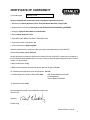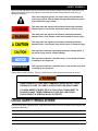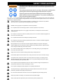
1
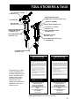
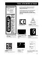
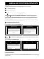
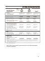
BR67
HYDRAULIC
BREAKER
Safety, Operation and Service
SERIOUS INJURY OR DEATH
COULD RESULT FROM THE IMPROPER REPAIR OR SERVICE
OF THIS TOOL.
User's Manual
REPAIRS AND / OR SERVICE TO
THIS TOOL MUST ONLY BE
DONE BY AN AUTHORIZED AND
CERTIFIED DEALER.
Read
The
Manual
Wear
Breathing
Protection
Wear
Hearing
Protection
Wear
Eye
Protection
Stanley Hydraulic Tools
Copyright © 2001 The Stanley
Works
OPS/SERVICE USA & CE VERSION
31994 Ver 5 04/2003
3810 SE Naef Road
Milwaukie, OR 97267-5698 USA
Phone: (503) 659-5660
Fax: (503) 652-1780
TABLE OF CONTENTS
Contents .............................................................................................................. 1
Certificate of Conformity ...................................................................................... 2
Safety Precautions .......................................................................................... 3 - 4
Tool Stickers and Tags ................................................................................... 5 - 6
Hydraulic Hose Requirements ........................................................................... 7
Hydraulic System Requirements ........................................................................ 8
Equipment Protection and Care .......................................................................... 9
Operation ........................................................................................................... 10
Service .......................................................................................................... 11-16
Accumulator Charging ....................................................................................... 17
Troubleshooting ................................................................................................ 18
Specifications .................................................................................................... 19
Accessories ....................................................................................................... 19
Special Tools ..................................................................................................... 19
Parts Lists .......................................................................................................... 20
Parts Illustration for Standard Handle Models .................................................. 21
Parts Illustration for Anti-Vibration Handle Models ........................................... 22
Warranty ............................................................................................................. 23
SERVICING BR67 BREAKERS: This manual contains safety, operation, Service and routine maintenance instructions. Stanley Hydraulic Tools recommends that servicing of hydraulic tools, other
than routine maintenance, must be performed by an authorized and certified dealer. Please read
the following warning.
SERIOUS INJURY OR DEATH COULD RESULT FROM THE IMPROPER REPAIR OR SERVICE OF THIS TOOL.
REPAIRS AND / OR SERVICE TO THIS TOOL MUST ONLY BE
DONE BY AN AUTHORIZED AND CERTIFIED DEALER.
For the nearest authorized and certified dealer, call Stanley Hydraulic Tools at one of the numbers listed on the back of this manual and ask for a Customer Service Representative.
1
CERTIFICATE OF CONFORMITY
I, the undersigned:
Hydraulic Tools
Winterling, David
Surname and First names
Hereby certify that the construction plant or equipment specified hereunder:
1. Manufacturer: Stanley Hydraulic Tools, 3810 Naef Road, Milwaukie, Oregon USA
2. Representative in the Union: Stanley Svenska AB, Box 9054, 400 92 Göteborg, SWEDEN
3. Category: Hydraulic Hand Held Concrete Breaker
4. Make: Stanley Hydraulic Tools
5. Type: BR6713801, BR6717201, BR6717202, BR6717801
6. Type serial number of equipment: All
7. Year of manufacture: Beginning 2002
Has been manufactured in conformity with the provisions of the Machinery Directive 98/37/EC
Harmonized standard applied: EN 792-4
We also declare that it meets the specification of Noise Directive 2000/14/EC, measured in accordance to
the Conformity Evaluation Method set out in Annex VI para. 5 and evaluated during production as in Annex
VI para. 6, 2 nd procedure.
8. Noise related value: 31 kg
9. Measured sound power on equipment representative of this type: 107 LwA
10. Guaranteed sound power level for this equipment: 112 LwA
11. Notified body for EC directive 2000/14/EC: 0404
SMP Svensk Maskinprovning AB
Fyrisborgsgatan 3
754 50 Uppsala, SWEDEN
12. Special Provisions: None
Issued at Stanley Hydraulic Tools, Milwaukie, Oregon USA
Date: 8/21/02
Signature
Position: Engineering Manager
P/N 52574 Rev.1, 8/21/02
2
SAFETY SYMBOLS
Safety symbols and signal words, as shown below, are used to emphasize all operator, maintenance and
repair actions which, if not strictly followed, could result in a life-threatening situation, bodily injury or
damage to equipment.
This is the safety alert symbol. It is used to alert you to potential personal injury hazards. Obey all safety messages that follow this symbol
to avoid possible injury or death.
This safety alert and signal word indicate an imminently hazardous
situation which, if not avoided, will result in death or serious injury.
This safety alert and signal word indicate a potentially hazardous
situation which, if not avoided, could result in death or serious injury.
This safety alert and signal word indicate a potentially hazardous
situation which, if not avoided, may result in minor or moderate injury.
This signal word indicates a potentially hazardous situation which, if
not avoided, may result in property damage.
This signal word indicates a situation which, if not avoided, will result
in damage to the equipment.
IMPORTANT
This signal word indicates a situation which, if not avoided, may result
in damage to the equipment.
Always observe safety symbols. They are included for your safety and for the protection of the tool.
SOME HYDRAULIC FLUIDS ARE FLAMMABLE, NEVER ALLOW THESE
HYDRAULIC FLUIDS TO COME IN CONTACT WITH AN OPEN FLAME.
IF A HOSE WERE TO BURST OR IF A TOOL LEAK OCCURS NEXT TO
AN OPEN FLAME, THESE HYDRAULIC FLUIDS WILL IGNITE AND
COULD RESULT IN SERIOUS INJURY OR DEATH.
LOCAL SAFETY REGULATIONS
Enter any local safety regulations here. Keep these instructions in an area accessible to the operator and
maintenance personnel.
3
SAFETY PRECAUTIONS
Tool operators and maintenance personnel must always comply with the safety
precautions given in this manual and on the stickers and tags attached to the
tool and hose.
These safety precautions are given for your safety. Review them carefully before
operating the tool and before performing general maintenance or repairs.
Supervising personnel should develop additional precautions relating to the
specific work area and local safety regulations. If so, place the added precautions in the space provided on page 3.
This tool will provide safe and dependable service if operated in accordance with the instructions given in this manual. Read and
understand this manual and any stickers and tags attached to the tool and hoses before operation. Failure to do so could result in
personal injury or equipment damage.
Operator must start in a work area without bystanders. The operator must be familiar with all prohibited
work areas such as excessive slopes and dangerous terrain conditions.
Establish a training program for all operators to ensure safe operations.
Do not operate the tool unless thoroughly trained or under the supervision of an instructor.
Always wear safety equipment such as goggles, head protection, and safety shoes at all times when
operating the tool.
Do not inspect or clean the tool while the hydraulic power source is connected. Accidental engagement of
the tool can cause serious injury.
Do not operate this tool without first reading the Operating Instructions.
Do not install or remove this tool while the hydraulic power source is connected. Accidental engagement
of the tool can cause serious injury.
Never operate the tool if you cannot be sure that underground utilities are not present. Underground
electrical utilities present an electrocution hazard. Underground gas utilities present an explosion hazard.
Other underground utilities may present other hazards.
Do not wear loose fitting clothing when operating the tool. Loose fitting clothing can get entangled with
the tool and cause serious injury.
Supply hoses must have a minimum working pressure rating of 2500 psi/175 bar.
Check fastener tightness often and before each use daily, also make sure all hose connections are tight.
The hydraulic circuit control valve must be in the “OFF” position when coupling or uncoupling the tool.
Wipe all couplers clean before connecting. Failure to do so may result in damage to the quick couplers
and cause overheating. Use only lint-free cloths.
Do not operate the tool at oil temperatures above 140° F/60° C. Operation at higher oil temperatures can
cause operator discomfort and may cause damage to the tool.
Do not operate a damaged, improperly adjusted, or incompletely assembled tool.
To avoid personal injury or equipment damage, all tool repair, maintenance and service must only be
performed by authorized and properly trained personnel.
Do not exceed the rated limits of the tool or use the tool for applications beyond its design capacity.
Always keep critical tool markings, such as labels and warning stickers legible.
Always replace parts with replacement parts recommended by Stanley Hydraulic Tools.
4
TOOL STICKERS & TAGS
SERIAL NO. STAMPING
11207 CIRCUIT "D" STICKER
(CE Models Only)
58604 GUARANTEED SOUND
POWER LEVEL STICKER (CE Models Only)
12542 NAME TAG
SERIAL NO. STAMPING
28322 CE LABEL
(CE Models Only)
28322 CE LABEL (CE Models Only)
11207 CIRCUIT "D" STICKER
(CE Models Only)
58604 GUARANTEED SOUND
POWER LEVEL STICKER
(CE Models Only)
28409 COMPOSITE STICKER
(CE Models Only)
28409 COMPOSITE STICKER
(CE Models Only)
28380 MODEL STICKER
(CE Models Only)
28376 NAME TAG (CE Models Only)
or 12542 NAME TAG
11208 SHANK LENGTH STICKER
(UK Models Only)
D A N G E R
D A N G E R
1. FAILURE TO USE HYDRAULIC HOSE LABELED AND CERTIFIED
AS NON-CONDUCTIVE WHEN USING HYDRAULIC TOOLS ON
OR NEAR ELECTRICAL LINES MAY RESULT IN DEATH OR SERIOUS INJURY.
BEFORE USING HOSE LABELED AND CERTIFIED AS NON-CONDUCTIVE ON OR NEAR ELECTRIC LINES BE SURE THE HOSE IS
MAINTAINED AS NON-CONDUCTIVE. THE HOSE SHOULD BE
REGULARLY TESTED FOR ELECTRIC CURRENT LEAKAGE IN
ACCORDANCE WITH YOUR SAFETY DEPARTMENT INSTRUCTIONS.
2. A HYDRAULIC LEAK OR BURST MAY CAUSE OIL INJECTION
INTO THE BODY OR CAUSE OTHER SEVERE PERSONAL INJURY.
The safety tag (p/n 15875)
at right is attached to the
tool when shipped from the
factory. Read and understand the safety instructions listed on this tag
before removal. We
suggest you retain this tag
and attach it to the tool
when not in use.
A
DO NOT EXCEED SPECIFIED FLOW AND PRESSURE FOR
THIS TOOL. EXCESS FLOW OR PRESSURE MAY CAUSE A
LEAK OR BURST.
B
DO NOT EXCEED RATED WORKING PRESSURE OF HYDRAU
LIC HOSE USED WITH THIS TOOL. EXCESS PRESSURE MAY
CAUSE A LEAK OR BURST.
C CHECK TOOL HOSE COUPLERS AND CONNECTORS DAILY
FOR LEAKS. DO NOT FEEL FOR LEAKS WITH YOUR HANDS.
CONTACT WITH A LEAK MAY RESULT IN SEVERE PERSONAL
INJURY.
D DO NOT LIFT OR CARRY TOOL BY THE HOSES. DO NOT
ABUSE HOSE. DO NOT USE KINKED, TORN OR DAMAGED
HOSE.
3. MAKE SURE HYDRAULIC HOSES ARE PROPERLY CONNECTED
TO THE TOOL BEFORE PRESSURING SYSTEM. SYSTEM PRESSURE HOSE MUST ALWAYS BE CONNECTED TO TOOL "IN" PORT.
SYSTEM RETURN HOSE MUST ALWAYS BE CONNECTED TO TOOL
"OUT" PORT. REVERSING CONNECTIONS MAY CAUSE REVERSE
TOOL OPERATION WHICH CAN RESULT IN SEVERE PERSONAL
INJURY.
4. DO NOT CONNECT OPEN-CENTER TOOLS TO CLOSED-CENTER
HYDRAULIC SYSTEMS. THIS MAY RESULT IN LOSS OF OTHER
HYDRAULIC FUNCTIONS POWERED BY THE SAME SYSTEM AND/
OR SEVERE PERSONAL INJURY.
5. BYSTANDERS MAY BE INJURED IN YOUR WORK AREA. KEEP BYSTANDERS CLEAR OF YOUR WORK AREA.
6. WEAR HEARING, EYE, FOOT, HAND AND HEAD PROTECTION.
7. TO AVOID PERSONAL INJURY OR EQUIPMENT DAMAGE, ALL TOOL
REPAIR MAINTENANCE AND SERVICE MUST ONLY BE PERFORMED BY AUTHORIZED AND PROPERLY TRAINED PERSONNEL.
I M P O R TA N T
I M P O R TA N T
READ OPERATION MANUAL AND
SAFETY INSTRUCTIONS FOR THIS
TOOL BEFORE USING IT.
READ OPERATION MANUAL AND
SAFETY INSTRUCTIONS FOR THIS
TOOL BEFORE USING IT.
USE ONLY PARTS AND REPAIR
PROCEDURES APPROVED BY
STANLEY AND DESCRIBED IN THE OPERATION
MANUAL.
USE ONLY PARTS AND REPAIR
PROCEDURES APPROVED BY
STANLEY AND DESCRIBED IN THE OPERATION
MANUAL.
TAG TO BE REMOVED ONLY BY
TOOL OPERATOR.
TAG TO BE REMOVED ONLY BY
TOOL OPERATOR.
SEE OTHER SIDE
15875
SEE OTHER SIDE
15875
SAFETY TAG P/N 15875 (shown smaller then actual size)
5
TOOL STICKERS & TAGS
BR67 BREAKER
Division of The Stanley Works
Stanley Hydraulic Tools
SERIAL NO.
FLOW 7-9 GPM/26-34 LPM
PRESS 1500-2000 PSI
105-140 BAR
ACCUMULATOR CHG
600 PSI/42 BAR
NITROGEN
NAME TAG STICKER p/n 12542
or p/n 29203
(shown smaller than actual size)
A name tag sticker is attached to the breaker.
Never exceed the flow and pressure levels
specified on this sticker.
The information listed on the name tag sticker
must be legible at all times. Replace this
sticker if it becomes worn or damaged. A replacement is available from your local Stanley
distributor.
CE STICKER p/n 28322
(shown approx size)
STANLEY LABEL STICKER
p/n 28376
(shown smaller than actual
size)
CIRCUIT "D" STICKER
p/n 11207
(shown smaller than actual size)
GUARANTEED SOUND POWER
LEVEL STICKER
p/n 58604
(shown smaller than actual size)
6"
✘
✔
6¼"
COMPOSITE STICKER
p/n 28409
(shown smaller than actual size)
MODEL No. LABEL
p/n 28380
(CE Models Only)
HEX SHANK STICKER p/n 11208
(UK Models Only)
6
HYDRAULIC HOSE REQUIREMENTS
HOSE TYPES
Hydraulic hose types authorized for use with Stanley Hydraulic Tools are as follows:
1
Certified non-conductive
2
Wire-braided (conductive)
3
Fabric-braided (not certified or labeled non-conductive)
Hose 1 listed above is the only hose authorized for use near electrical conductors.
Hoses 2 and 3 listed above are conductive and must never be used near electrical conductors.
To help ensure your safety, the following DANGER tags are attached to all hose purchased from Stanley
Hydraulic Tools. DO NOT REMOVE THESE TAGS.
If the information on a tag is illegible because of wear or damage, replace the tag immediately. A new tag
may be obtained at no charge from your Stanley Distributor.
1
CERTIFIED NON-CONDUCTIVE HOSE
D A N G E R
D A N G E R
1 FAILURE TO USE HYDRAULIC HOSE LABELED AND CERTIFIED AS NON-CONDUCTIVE WHEN
USING HYDRAULIC TOOLS ON OR NEAR ELECTRIC LINES MAYRESULT IN DEATH OR SERIOUS
INJURY.
FOR PROPER AND SAFE OPERATION MAKE SURE THAT YOU HAVE BEEN PROPERLY TRAINED IN
CORRECT PROCEDURES REQUIRED FOR WORK ON OR AROUND ELECTRIC LINES.
3. DO NOT EXCEED HOSE WORKING PRESSURE OR ABUSE HOSE. IMPROPER USE OR HANDLING
OF HOSE COULD RESULT IN BURST OR OTHER HOSE FAILURE. KEEP HOSE AS FAR AWAY AS
POSSIBLE FROM BODY AND DO NOT PERMIT DIRECT CONTACT DURING USE. CONTACT AT THE
BURST CAN CAUSE BODILY INJECTION AND SEVERE PERSONAL INJURY.
2. BEFORE USING HYDRAULIC HOSE LABELED AND CERTIFIED AS NON-CONDUCTIVE ON OR
NEAR ELECTRIC LINES. WIPE THE ENTIRE LENGTH OF THE HOSE AND FITTING WITH A CLEAN
DRY ABSORBENT CLOTH TO REMOVE DIRT AND MOSISTURE AND TEST HOSE FOR MAXIMUM
ALLOWABLE CURRENT LEAKAGE IN ACCORDANCE WITH SAFETY DEPARTMENT
INSTRUCTIONS.
4. HANDLE AND ROUTE HOSE CAREFULLY TO AVOID KINKING, ABRASION, CUTTING, OR CONTACT
WITH HIGH TEMPERATURE SURFACES. DO NOT USE IF KINKED. DO NOT USE HOSE TO PULL OR
LIFT TOOLS, POWER UNITS, ETC.
5. CHECK ENTIRE HOSE FOR CUTS CRACKS LEAKS ABRASIONS, BULGES, OR DAMAGE TO
COUPLINGS IF ANY OF THESE CONDITIONS EXIST, REPLACE THE HOSE IMMEDIATELY. NEVER
USE TAPE OR ANY DEVICE TO ATTEMPT TO MEND THE HOSE.
DO NOT REMOVE THIS
TA G
DO NOT REMOVE THIS
TA G
This tag is attached to all certified non-conductive hose.
6. AFTER EACH USE STORE IN A CLEAN DRY AREA.
SEE OTHER SIDE
SIDE 1
SEE OTHER SIDE
(shown smaller than actual size)
SIDE 2
2 AND 1 3WIRE-BRAIDED AND FABRIC-BRAIDED (NOT CERTIFIED OR LABELED NON-CONDUCTIVE) HOSE
This tag is attached to all conductive hose.
DO NOT REMOVE THIS
TA G
2. FOR PROPER AND SAFE OPERATION MAKE SURE THAT YOU HAVE BEEN PROPERLY TRAINED IN
CORRECT PROCEDURES REQUIRED FOR WORK ON OR AROUND ELECTRIC LINES.
5. CHECK ENTIRE HOSE FOR CUTS CRACKS LEAKS ABRASIONS, BULGES, OR DAMAGE TO
COUPLINGS IF ANY OF THESE CONDITIONS EXIST, REPLACE THE HOSE IMMEDIATELY. NEVER
USE TAPE OR ANY DEVICE TO ATTEMPT TO MEND THE HOSE.
6. AFTER EACH USE STORE IN A CLEAN DRY AREA.
3. DO NOT EXCEED HOSE WORKING PRESSURE OR ABUSE HOSE. IMPROPER USE OR HANDLING
OF HOSE COULD RESULT IN BURST OR OTHER HOSE FAILURE. KEEP HOSE AS FAR AWAY AS
POSSIBLE FROM BODY AND DO NOT PERMIT DIRECT CONTACT DURING USE. CONTACT AT
THE BURST CAN CAUSE BODILY INJECTION AND SEVERE PERSONAL INJURY.
4. HANDLE AND ROUTE HOSE CAREFULLY TO AVOID KINKING, CUTTING, OR CONTACT WITH
HIGH TEMPERATURE SURFACES. DO NOT USE IF KINKED. DO NOT USE HOSE TO PULL OR LIFT
TOOLS, POWER UNITS, ETC.
DO NOT REMOVE THIS
TA G
D A N G E R
D A N G E R
1 DO NOT USE THIS HYDRAULIC HOSE IN OR NEAR ELECTRIC LINES. THIS HOSE IS NOT LABELED
OR CERTIFIED AS NON-CONDUCTIVE. USING THIS HOSE ON OR NEAR ELECTRICAL LINES MAY
RESULT IN DEATH OR SERIOUS INJURY.
SEE OTHER SIDE
SEE OTHER SIDE
SIDE 1
(shown smaller than actual size)
SIDE 2
HOSE PRESSURE RATING
The rated working pressure of the hydraulic hose must be equal or higher than the relief valve setting on the
hydraulic system.
7
HTMA Requirements
Hydraulic System
Requirements
Tool
Category:
Flow rate
Tool Operating Pressure
20Lpm at 138bar
BHTMA CATEGORY
30Lpm at 138bar
BHTMA CATEGORY
Type I
Type II
Type III
4-6 GPM (15-23 lpm)
2000 psi (138 bar)
7-9 GPM (26-34 lpm)
2000 psi (138 bar)
11-13 GPM (42-49 lpm)
2000 psi (138 bar)
(at the power supply outlet)
System relief valve setting
(at the power supply outlet)
Maximum back pressure
(at tool end of the return hose)
Measured at a max. fluid viscosity of:
(at min. operating temperature)
Temperature
Sufficient heat rejection capacity
to limit max. fluid temperature to:
(at max. expected ambient temperature)
Min. cooling capacity
at a temperature difference of
between ambient and fluid temps
2100-2250
2100-2250
2100-2250
(145-155 bar)
(145-155 bar)
(145-155 bar)
250 psi
250 psi
250 psi
(17 bar)
(17 bar)
(17 bar)
400 SSU
400 SSU
400 SSU
(82 centistokes)
(82 centistokes)
(82 centistokes)
140° F (60° C)
140° F (60° C)
140° F (60° C)
3 hp (2.24 kW)
40° F (22° C)
5 hp (3.73 kW)
40° F (22° C)
7 hp (5.22 kW)
40° F (22° C)
NOTE: Do not operate the tool at oil temperatures above 140° F (60° C). Operation at higher temperatures can cause operator
discomfort at the tool.
Filter
Min. full-flow filtration
sized for flow of at least:
25 microns
30 GPM (114 lpm)
25 microns
30 GPM (114 lpm)
25 microns
30 GPM (114 lpm)
(For cold temp. startup and max. dirt-holding capacity)
Hydraulic fluid
Petroleum based
(premium grade, anti-wear, non-conductive)
Viscosity
(at min. and max. operating temps)
100-400 SSU*
(20-82 centistokes)
100-400 SSU*
(20-82 centistokes)
100-400 SSU*
(20-82 centistokes)
NOTE: When choosing hydraulic fluid, the expected oil temperature extremes that will be experienced in service determine the
most suitable temperature viscosity characteristics. Hydraulic fluids with a viscosity index over 140 will meet the requirements over
a wide range of operating temperatures.
*SSU = Saybolt Seconds Universal
NOTE: These are general hydraulic system requirements. See tool Specification page for
tool specific requirements.
8
Equipment Protection and Care
In addition to the Safety
Precautions on page 3 & 4
of this manual, observe the
following for equipment
protection and care.
• Make sure all couplers are wiped clean before connection.
• The hydraulic circuit control valve must be in the “OFF” position when coupling or uncoupling
hydraulic tools. Failure to do so may result in damage to the quick couples and cause overheating
of the hydraulic system.
• Always store the tool in a clean dry space, safe from damage or pilferage.
• Make sure the circuit PRESSURE hose (with male quick disconnect) is connected to the “IN” port.
The circuit RETURN hose (with female quick disconnect) is connected to the opposite port. Do not
reverse circuit flow. This can cause damage to internal seals.
• Always replace hoses, couplings and other parts with replacement parts recommended by Stanley
Hydraulic Tools. Supply hoses must have a minimum working pressure rating of 2500 psi/172 bar.
• Do not exceed the rated flow (see Specifications) page 19 in the manual for correct flow rate and
model number. Rapid failure of the internal seals may result.
• Always keep critical tool markings, such as warning stickers and tags legible.
• Do not force a small breaker to do the job of a large breaker.
• Keep tool bit sharp for maximum breaker performance. Make sure that tool bits are not chipped or
rounded on the striking end.
• Never operate a breaker without a tool bit or without holding it against the work surface. This puts
excessive strain on the breaker foot.
• Tool repair should be performed by experienced personnel only.
• Make certain that the recommended relief valves are installed in the pressure side of the system.
• Do not use the tool for applications for which it was not intended.
9
OPERATION
PREOPERATION
PROCEDURES
PREPARATION FOR INITIAL
USE
Each unit as shipped has no special unpacking or
assembly requirements prior to usage. Inspection
to assure the unit was not damaged in shipping and
does not contain packing debris is all that is
required.
CHECK HYDRAULIC POWER
SOURCE
1. Using a calibrated flowmeter and pressure
gauge, check that the hydraulic power source
develops a flow of 7-9 gpm/26-34 lpm at 1500-2000
psi/105-140 bar.
2. Make certain the hydraulic power source is
equipped with a relief valve set to open at 2100-2250
psi/145-155 bar minimum.
3. Check that the hydraulic circuit matches the tool
for open-center (OC) operation.
CHECK TOOL
1. Make sure all tool accessories are correctly
installed. Failure to install tool accessories properly
can result in damage to the tool or personal injury.
2. There should be no signs of leaks.
CONNECT HOSES
1. Wipe all hose couplers with a clean lint-free cloth
before making connections.
2. Connect the hoses from the hydraulic power
source to the hose couplers on the breaker. It is a
good practice to connect the return hose first and
disconnect it last to minimize or avoid trapped
pressure within the breaker.
3. Observe flow indicators stamped on hose
couplers to be sure that oil will flow in the proper
direction. The female coupler is the inlet coupler.
NOTE: The pressure increase in uncoupled
hoses left in the sun may result in making them
difficult to connect. When possible, connect
the free ends of operating hoses together.
OPERATING
PROCEDURES
1. Observe all safety precautions.
2. Move the hydraulic circuit control valve to the
"ON" position.
3. Place the tool bit firmly on the surface to be
broken.
4. Squeeze the trigger to start the breaker. Adequate down pressure is very important.
NOTE: Partially depressing the trigger allows the
tool to operate at a slow speed, making it easy to
start the tool bit into the surface to be broken.
3. The tool should be clean, with all fittings and
fasteners tight.
CHECK TRIGGER MECHANISM
1. Check that the trigger operates smoothly and is
free to travel between the "ON" and "OFF" positions.
COLD WEATHER
OPERATION
If the breaker is to be used during cold weather,
preheat the hydraulic fluid at low engine speed.
When using the normally recommended fluids, fluid
temperature should be at or above 50° F/10° C
(400 ssu/82 centistokes) before use.
10
SERVICE INSTRUCTIONS
Good maintenance practices will keep the breaker on
the job and increase its service life.
A very important maintenance practice is to keep the
hydraulic fluid clean at all times. Contaminated
hydraulic fluid causes rapid wear and/or failure of
internal parts.
Follow the procedures contained in the HYDRAULIC
SYSTEM REQUIREMENTS section of this manual to
ensure peak performance from the tool. Never disassemble the breaker unless proper troubleshooting
procedures have isolated the problem to an internal
part. Then, only disassemble it to the extent necessary to replace the defective part. KEEP CONTAMINANTS SUCH AS DIRT AND GRIT AWAY FROM
INTERNAL PARTS AT ALL TIMES.
3. Remove the valve cap assembly (74) from the top of
the handle. Loosen the 5/8- inch hex charging valve
lock nut 1-1/2 turns. Discharge the accumulator down
to approximately 20 psi/1.4 bar.
IMPORTANT
Do not completely discharge the accumulator
at this time.
4. Remove the four side rod nuts (66). Remove the
breaker foot assembly (61 or 87) by tapping the top of
the flange with a plastic or rubber hammer to drive it
from the flow sleeve tube (40). Remove the o-ring, rod
wiper and cup seal (62, 63 & 65) from the foot using
the proper o-ring tools to avoid damage to grooved
surfaces.
Always determine and correct the cause of the
problem prior to reassembly. Further wear and tool
failure can result if the original cause is not corrected.
5. Remove the handle assembly (59) from the flow
sleeve assembly (40) by tapping on alternate ends of
the side rods (46) with a plastic or rubber hammer
while pulling on the handle.
DISASSEMBLY
AUTOMATIC VALVE BODY & ACCUMULATOR
ASSEMBLY
PRIOR TO DISASSEMBLY
• Clean the exterior of the tool.
• Obtain a seal kit to replace all seals exposed during
disassembly. Note the orientation of seals before
removing them. Install new seals in the same position
as original seals.
HANDLE & ACCUMULATOR
DISASSEMBLY
Standard Handle Models
Refer To Illustration 2.
1. Secure the breaker in a bench vise, with the “IN”
and “OUT” ports up, clamping on the flow sleeve tube
between the side rods. Soft vise jaws are recommended.
2. Remove the pigtail hose assemblies.
Note: The breaker is full of fluid and will drip from the
ports when the hoses are removed.
6. If the automatic valve body (56) remains in the
handle assembly, the accumulator assembly and
automatic valve body can be removed by placing a 3/
4-inch hex deep socket with a 6-inch/15 cm extension
over the charging valve (21) and tapping the extension
with a plastic or rubber hammer.
Note: Make sure the thin washer (42) between the
automatic valve body and the accumulator chamber
(79) is properly located in its counterbore before
driving the automatic valve body and accumulator out
of the handle.
7. If the accumulator cylinder (70) remains inside the
handle, it can be removed using the accumulator
cylinder puller (Part Number 05640) which seats on
the inside lower contour of the accumulator cylinder.
Use a rod that extends through the charge valve hole
in the handle and drive out the cylinder by tapping on
the rod or use a slide hammer through the 1/2-inch/
12.5 mm hole provided in the puller.
8. If the entire accumulator assembly was removed in
step 4, discharge the accumulator assembly completely and proceed to step 7.
9. To remove the accumulator chamber and diaphragm
(51) from the accumulator cylinder, Place
11
the assembly on disassembly tools (Part Numbers
05508 and 04910). Use a rag in the bottom of the flow
sleeve removal tube (Part Number 04910) to protect
the accumulator chamber. Drive the chamber and
diaphragm out by tapping or pushing with an arbor
press on the charge valve end while protecting the
valve with a 3/4-inch hex deep socket.
10. Squeeze the accumulator diaphragm and slide it
off the charge valve end of the accumulator chamber.
3. Remove the handle assembly from the flow sleeve
assembly by tapping on alternate ends of the side
rods with a plastic or rubber hammer while pulling on
the handle.
4. If the automatic valve body (56) remains in the
handle assembly, it can be removed by using a
special tool (30939 sleeve & 05046 bearing puller).
11. Remove the cup seal (43) and back-up washer
(37) from the accumulator chamber.
5. The spacer is removed by using a 7/8 inch collet
(30956 collet) and a bearing puller from the 05064
bearing puller kit.
12. Secure the accumulator chamber in a vise with
soft jaws to remove the charging valve.
6. The sintered filter (33) and o-rings (34) are removed
by simply picking them out.
IMPORTANT
Avoid damage to the counterbore of the
chamber.
TRIGGER
13. Remove the trigger (12) from the handle by driving
out the 1/4-inch/6.4 mm diameter Spirol Pin.
ACCUMULATOR
7. Clamp the handle assembly in a vice with soft jaws
and unscrew the charge valve (21). Make sure the
accumulator has been discharged before removing the
charge valve.
8. Unscrew the accumulator plug (52) using special
tool 29135 accumulator plug wrench.
VALVE SPOOL
9. Lift out the accumulator diaphragm (51).
14. Remove the valve spool (7) by driving out two 3/16
x 1-3/8 inch/5 mm x 35 mm roll pins (77) and tap the
end of the spool. The valve spring (8) will eject the
spool from the bore bringing the washer and bushing
with it.
15. Remove the valve spool spring by turning the
handle on end.
16. Remove the orifice plug (30) from the bottom of the
valve spool bore with a long 1 1/4-inch hex wrench.
TRIGGER
10. Remove 4 capscrews (9) and lift off the top plate
(92).
11. Unscrew the two pivot screws (49) and lift out the
two handles (11 & 13) and four springs (24 & 25).
Remove the lever (10) and trigger (12) from the handle
by driving out the roll pins (23).
VALVE SPOOL
HANDLE & ACCUMULATOR
DISASSEMBLY
Anti-Vibration Handle Models
Refer to Illustration 1.
1. Remove the modified plug (20) and discharge the
accumulator completely.
2. Remove the four side rod nuts (66). Remove the
foot assembly (61) by tapping the top of the flange
with a plastic or rubber hammer to drive it from the
flow sleeve tube (40). Remove the o-ring, rod seal and
cup seal (62, 63 & 65) from the foot using the proper
o-ring tools to avoid damage to grooved surfaces.
12. Remove the spirolox retaining ring, then remove
the SAE plug (32) located at the bottom of the spool
bore. Pick out the spring (8) and then push the valve
spool (7) out.
FLOW SLEEVE TUBE
DISASSEMBLY
1. Follow steps 1 through 3 of the HANDLE AND
ACCUMULATOR DISASSEMBLY for STANDARD
HANDLES or steps 1 through 3 for ANTI-VIBRATION
HANDLES.
2. If the automatic valve body remains in the flow
sleeve tube, complete the following steps.
12
a. Remove the washer (42) and piston (17).
b. Place the split rings (p/n 04908) between the
automatic valve body and flow sleeve tube.
c. Place the flow sleeve assembly (with split rings
in place) on the flow sleeve removal tube (p/n
04910) with the automatic valve body down.
d. Using an arbor press and an aluminum disc or
accumulator cylinder puller (p/n 05640) to protect
the flow sleeve, push on the flow sleeve (45) to
remove the automatic valve body.
IMPORTANT
Use a rag in the bottom of the removal tube to
protect the automatic valve body when it
drops out.
e. The automatic valve body, automatic valve (47),
four 5/16 x 2-inch/8 mm x 51 mm push pins (54)
from the flow sleeve and two 3/16 x 1-1/4 inch/5
mm x 32 mm push pins (48) from the automatic
valve body will come out.
3. Remove the flow sleeve from the flow sleeve tube
(40) as follows:
a. Place the split ring (p/n 04908) on top of the
flow sleeve removal tube (p/n 04910).
b. Place the flow sleeve tube assembly on top of
split rings.
c. With an arbor press, and an aluminum disc or
accumulator cylinder puller (p/n 05640) to protect
the flow sleeve, push the flow sleeve out of the
tube.
IMPORTANT
Use a rag in the bottom of the removal tube
to protect the flow sleeve when it drops out.
4. The hex bushing (53) is removed by pressing it out
using a 100 ton press.
EASI-RIDETM FOOT
To remove the collar support (83) and spring (82) follow
the steps below.
1. Follow steps 2 and 3 above to remove the latch,
detent and spring.
2. Press down on the collar support (83) from the latch
end to retract it from the retaining ring (a long bolt with
large washers may be placed through the foot assembly to hold the collar support in the retracted position).
3. Using a small punch, insert it through the hole in
the foot (87) and press on the retaining ring (85). Hook
the retaining ring with a hook type tool and pull it out.
4. Pull the collar support and spring out.
5. The hex bushing (81) is removed by pressing it out
using a 100 ton press.
ASSEMBLY
PRIOR TO ASSEMBLY
• Clean all parts with a degreasing solvent.
• Ensure that all seals exposed during disassembly
are replaced with new parts.
• Apply clean grease or o-ring lubricant to all parts
during assembly.
• Obtain a seal kit so that all seals exposed during
disassembly can be replaced. Note: For orientation of
parts identified in the following procedures, see the
parts illustration.
HANDLE ASSEMBLY
Standard Handle Models
FOOT DISASSEMBLY
1. Follow steps 2 and 3 of the HANDLE AND ACCUMULATOR DISASSEMBLY for STANDARD
HANDLES or steps 3 and 4 for ANTI-VIBRATION
HANDLES.
2. Remove the latch (67) by first removing the nut (68),
washer (58) and bolt (60).
3. The detent (70) and spring (69) can be removed
after the latch is removed.
Refer to Illustration 2.
1. Install the orifice plug (30) in the bottom of the valve
spool bore with a long 1/4-inch hex wrench.
2. Replace (in this order) the spring (8), valve spool
(Caution: the valve spool is a two peice spool, a spool
and spool rod with an o-ring attached to the spool rod.
Make sure the spool rod is properly seated in the
spool and that they do not separate during installation
into the valve spool bore. (7), bushing (4) (with wiper
ring (3) toward stem end of valve spool) and washer (2)
in the valve spool Bore.
13
Secure by driving the two 3/16 x 1-5/8 inch/5 x 41 mm
spirol pins (77) through the handle on top of the
washer.
3. Replace the trigger (12). Install a 1/4-inch/6.4 mm
diameter spirol pin (72). To ease installation of the pin,
align the trigger with a 1/4-inch/6 mm diameter rod or
punch from the opposite side of the handle.
HANDLE ASSEMBLY
Anti-Vibration Handle Models
Refer to Illustration 1.
1. Install the orifice plug (30) through the bottom port
(OUT PORT) into the threaded hole near the bottom of
the spool bore.
2. Place the accumulator valve block (50) on a bench
top with trigger handle side down. Lubricate an o-ring
(34) and place it into the bottom of the bore in the
valve block. Place the sintered filter (33) on top of this
o-ring. Lubricate another o-ring (34) and place it on
top of the sintered filter.
9. Place the top plate (92) over the top of the accumulator valve block and secure with 4 capscrews (9).
10. Set the completed assembly aside.
FLOW SLEEVE TUBE ASSEMBLY
The best way to assemble the flow sleeve (45), automatic valve body (56) and piston (17) is by using an
assembly fixture such as that shown in figure 1. The
fixture permits the parts to be stacked vertically during
the assembly process. After the parts are stacked, the
handle assembly can then be placed on top of the
stacked parts and tapped into place.
The assembly fixture shown in figure 1 should be
constructed of aluminum or brass and should be at
least 3-1/2 in/88 mm high but no more than 8 in/203
mm high.
The instructions in this section require the use of the
assembly fixture shown in figure 1. If a fixture cannot be
acquired, use an assembled foot assembly and clamp
it into a vice.
3. Lubricate o-ring (35) and install it onto the spacer
(36). Install the backup washer (37) and cup seal (43)
(with lips facing out) into the bore in the spacer. Install
the completed assembly into the accumulator valve
block.
4. Install the SAE plug (32).
5. Turn the valve block over (trigger handle side up).
Install (in this order) the spring (8), valve spool
(Caution: the valve spool is a two peice spool, a spool
and spool rod with an o-ring attached to the spool rod.
Make sure the spool rod is properly seated in the
spool and that they do not separate during installation
into the valve spool bore. (7), bushing (with rod wiper
(3), o-ring (6) and o-ring (5) installed) and washer into
the valve spool bore. Secure by installing the spirolox
retaining ring (1).
Figure 1.
1. Lubricate the flow sleeve (45) and install it into the
flow sleeve tube (40). Orientation is as shown in the
parts illustration. The flow sleeve has a wide groove
around the outside of one end. Install this end first.
Then place the flow sleeve tube and flow sleeve on top
of the assembly fixture shown in figure 1.
6. Install the springs (24) and (25).
7. Install the trigger (12) into the trigger handle (13)
and secure with a spirol pin (23). Install the lever (10)
into the trigger handle and secure with a spirol pin.
Install the completed assembly onto the accumulator
valve block and secure with a pivot screw (49) applied
with Kopr-Kote antiseize compound and Loctite on the
threads.
8. Install the handle (11) onto the accumulator valve
block and secure with a pivot screw applied with KoprKote antiseize compound and Loctite on the threads.
2. Apply grease and install an o-ring (44) onto the flow
sleeve tube.
3. Apply lubricant and install 4 push pins (54) into the
holes in the top of the flow sleeve. One end of each
push pin contains a machined surface. This surface
must be facing up as each push pin is installed. Each
push pin must slide freely in or out of the hole in the
flow sleeve. If a push pin does not slide freely or seems
to stick, the hole may contain contamination or the top
edge of the hole contains a burr. Remove burrs with a
deburring tool, clean the
14
hole thoroughly and try the push pin again.
4. Tap the roll pin (55) into the hole on the automatic
valve body (56).
5. Apply grease and install an o-ring (44) onto the
valve body (56).
6. Lubricate and install 2 push pins (48) into the holes
in the valve body. One end of each push pin contains
a machined surface. This surface must be facing up
as each push pin is installed. Each push pin must
slide freely in or out of the hole in the valve body. If a
push pin does not slide freely or seems to stick, the
hole may contain contamination or the top edge of the
hole contains a burr. Remove burrs with a deburring
tool, clean the hole thoroughly and try the push pin
again.
7. Lubricate the automatic valve (47) and install it into
the valve body. The automatic valve must freely slide
back and forth. If it does not, the valve body or valve
may contain contaminants or the bore of the valve
body contains burrs. Remove the push pins and
scrub the bore of the valve body with emery cloth and
then thoroughly clean the bore, push pin holes and
valve. Reinstall the push pins and valve.
8. Grasp the automatic valve body and valve so that
one or more fingers are gripping the valve to prevent it
and the push pins from falling out when the valve body
and valve are turned upside down (roll pin facing
down). Place the assembly on top of the flow sleeve
making sure the roll pin aligns with the appropriate
hole in the flow sleeve.
9. Lubricate and install the piston (17) into the top of
the automatic valve body.
10. Install the washer (42), smaller diameter first, over
the stem of the piston and onto the automatic valve
body.
11. If you are working with a standard handle model,
proceed to the steps below. If you are working with an
anti-vibration handle model, proceed to step 1. under
"INSTALLING THE HANDLE ASSEMBLY, for AntiVibration Handle Models".
ACCUMULATOR - Standard Handle Models Only
12. Screw the charging valve (21) into the accumulator
chamber.
13. Apply a light coating of WD-40 to the accumulator
diaphragm (51) and accumulator chamber (79) and
slide the accumulator diaphragm onto the accumulator chamber from the charging valve end.
14. Use grease or rubber lubricant on the inside of the
accumulator cylinder (70) and the outside diameter of
the diaphragm. Push the accumulator chamber and
diaphragm, charging valve end first, halfway into the
accumulator cylinder. The parts are assembled from
the end of the cylinder with the chamfer on the outside
diameter. Be sure the accumulator diaphragm is free
of wrinkles and the seal bead is in its groove before
completing the assembly. An arbor press is required
to completely seat the assembly using short movements during the last 1/2-inch/12 mm of travel to
gently seat the diaphragm.
IMPORTANT
Do not use a hammer or powered arbor
press.
15. Test charge the accumulator assembly as follows:
a. Place the accumulator assembly in a vise with
soft jaws clamping on ends of the accumulator
chamber. Do not overtighten the vise and distort
the accumulator cylinder.
b. Loosen the charging valve lock nut 1-1/2 turns.
c. Charge the accumulator with nitrogen to 600
psi/41 bar. (It may be necessary to charge it 5075 psi/3.4-5 bar high to overcome the pressure
drop through the charging system.)
d. Check for leaks.
16. Apply grease and install a new o-ring (35) around
the accumulator cylinder. Apply grease and install a
new back-up washer (37) and cup seal (43) (lips
facing out) in the accumulator chamber counterbore.
17. Install the accumulator assembly over the stem of
the piston and down to the top of the automatic valve
body.
INSTALLING THE HANDLE
ASSEMBLY
Standard Handle Models
Refer to Illustration 2.
1. Apply grease liberally to the o-ring surfaces on the
accumulator, automatic valve body, flow sleeve tube
and to the bore of the handle assembly.
15
2. Place the handle assembly over the top of the
accumulator and then tap it down until the lower part
of the handle block covers the o-ring on the flow sleeve
tube.
Nm using special tool 29135 Accumulator Plug
Wrench.
3. Lay the completed handle and flow sleeve assembly over being careful to prevent movement of the flow
sleeve when the assembly fixture is removed.
9. Charge the accumulator with 600 psi/42 bar
nitrogen as described in the "CHARGING THE
ACCUMULATOR" section.
4. Place the completed assembly horizontally (oil
ports up) in a vice with soft jaws and clamp on the flow
sleeve tube.
10. Install the plug (20).
5. Follow steps 1 through 6 of the "FOOT ASSEMBLY" for installation of the foot assembly.
6. Charge the accumulator with 600 psi/42 bar
nitrogen as described in the "CHARGING THE
ACCUMULATOR" section.
7. Install the valve cap (74).
INSTALLING THE HANDLE
ASSEMBLY
Anti-Vibration Handle Models
Refer to Illustration 1.
1. Apply grease liberally to the o-ring surfaces on the
automatic valve body, flow sleeve, the cup seal in the
spacer and the bore of the handle assembly.
2. Place the handle assembly over the piston and
automatic valve being careful to align the spacer with
the stem of the piston. Tap the handle down until the
lower part of the handle block covers the o-ring on
the flow sleeve tube.
3. Lay the completed handle and flow sleeve assembly over being careful to prevent movement of the flow
sleeve when the assembly fixture is removed.
4. Place the completed assembly horizontally
(accumulator up) in a vice with soft jaws and clamp on
the flow sleeve tube.
8. Install the charge valve (21).
FOOT ASSEMBLY
1. If the hex bushing was removed, reinstall it using a
50 ton press making sure the hex is properly aligned
for the tool bit.
2. If servicing an EASI-RIDETM foot, install the spring
(82) and collar support (83) followed by the retaining
ring (85).
3. Apply grease and install the rod wiper (63) below
the seal insert.
4. Install the seal carrier (64) into the bottom of the
flow sleeve tube.
5. Apply grease and install the cup seal (65) into the
seal carrier.
6. Apply grease and install the o-ring (62).
7. Install the spring (69) and detent (70). Install the
two rubber sleeves (57). Place a washer (58) over the
bolt (60), place the latch (67) between the two ears on
the foot and push the bolt through it. Place a washer
(58) on the thread end of the bolt and then thread on
the nut (68). Tighten the nut until the treaded end of
the bolt is even with the outside surface of the nut.
8. Install the foot over the side rods and into the flow
sleeve tube.
9. Install the four side rod nuts. Tighten in 20 ft Ib/25
Nm increments to 75 ft Ib/100 Nm in a cross pattern.
5. Follow steps 1 through 6 of the "FOOT ASSEMBLY" for installation of the foot assembly.
ACCUMULATOR
6. Lubricate the diaphragm (51) inside and out with
WD40 and install it into the handle.
7. Apply Kopr-Kote antiseize to the thread surfaces of
the accumulator plug (52) and handle assembly and
install the accumulator plug. Tighten to 200 lb. ft./270
16
CHARGING THE ACCUMULATOR
CHARGING THE ACCUMULATOR
To check or charge the accumulator the following
equipment is required:
• Accumulator tester (Part Number 02835).
• Charging assembly (Part Number 15304)
(includes a guage w/snub valve, hose and fitting).
• NITROGEN bottle with a 800 psi/56 bar minimum
charge.
1. On charge valves containing 5/8 inch hex locking
nuts, first loosen the locking nut 1-1/2 turns.
2. Holding the chuck end of the Stanley tester (p/n
02835), turn the gauge fully counterclockwise to
ensure the stem inside the chuck is completely
retracted.
3. Thread the tester onto the charging valve of the tool
accumulator (do not advance the gauge-end into the
chuck end. Turn as a unit). Seat the chuck on the
accumulator charging valve and hand tighten only.
4. Advance the valve stem by turning the gauge- end
clockwise.
5. Connect the charge fitting on the hose to the
charge valve on the 02835 Tester.
6. With the gauge and snub valve attached to the
nitrogen bottle, and with the snub valve closed, open
the nitrogen bottle valve.
NOTE: It may be necessary to adjust the charge at
650-700 psi/45-48 bar to overcome any pressure drop
through the charging system.
7. While watching the pressure gage open the snub
valve allowing the gauge to read 600 to 700 psi/42 to
48 bar, close the snub valve on the charging assembly
and also on the nitrogen bottle, remove the charging
assembly from the accumulator tester.
8. Turn the gauge end of the tester fully counterclockwise to retract the plunger in the chuck. Then remove
the tester from the charge valve.
9.On charge valves containing 5/8 inch hex locking
nuts, tighten the locking nut.
TESTING THE ACCUMULATOR
PRESSURE
1. Follow instructions 1 through 4 under "CHARGING
THE ACCUMULATOR".
2. Read the pressure on the gauge (pressure should
be between 500 & 600 psi/35 & 42 bar.
3. If the pressure is low, recharge the tool.
Gauge w/
Snub Valve
Charge
Fitting
Nitrogen
Tank
Charging
Valve
31254 ACCUMULATOR
CHARGE KIT
Includes: Gauge w/ snub valve,
hose w/charge fitting, 02835 tester,
and box (not pictured).
Hose
Gauge
Chuck
02835 TESTER
17
TROUBLESHOOTING
If symptoms of poor performance develop, the
following chart can be used as a guide to correct
the problem.
supplying the correct hydraulic flow and pressure to
the breaker as listed in the table. Use a flowmeter
known to be accurate. Check the flow with the
hydraulic oil temperature at least 80°F/27°C.
When diagnosing faults in operation of the tool,
always check that the hydraulic power source is
Breaker does not run.
Breaker does not hit
effectively.
Breaker operates slow.
Power unit not functioning.
Check power unit for proper flow
and pressure (7-9 gpm / 26-34
lpm, 2000 psi / 140 bar).
Couplers or hoses blocked.
Remove restriction.
Presssure and return line hoses
reversed at ports.
Be sure hoses are connected to
their proper ports.
Mechanical failure of piston or
automatic valve.
Have inspected and repaired by
authorized dealer.
Power unit not functioning.
Check power unit for proper flow
and pressure (7-9 gpm / 26-34
lpm, 2000 psi / 140 bar).
Couplers or hose blocked.
Remove restriction,
Low accumulator charge
(pressure hose will pulse more
than normal).
Have recharged by authorized
dealer.
Fluid too hot
(above 140° F / 60° C).
Provide cooler to maintain proper
fluid temperature.
Collar support not sliding freely
in the foot bore (Easi-RideTM)
Remove, clean and replace as
required.
Low oil flow from power unit.
Check power source for proper
flow.
High backpressure.
Check hydraulic system for
excessive backpressure and
correct as required.
Orifice Plug Blocked.
Remove restriction.
18
SPECIFICATIONS
Pressure Range .......................................................................................................................................... 1500-2000 psi/104-140 bar
Blows Per Minute ............................................................................................................................................................... 1300 to 1800
Maximum Back Pressure .................................................................................................................................................. 250 psi/17 bar
Flow Range ....................................................................................................................... (HTMA Type II) 7-9 gpm/26-34 lpm
EHTMA Category D ..................................................................................................................................................... 30 lpm @ 138 bar
Porting ............................................................................................................................................................................... -8 SAE O-ring
Couplers ....................................................................................................................... HTMA/EHTMA Flush Face Type Male & Female
Connect Size and Type .................................................................................................................................. 3/8 in. Male Pipe Adapter
Hose Whips ....................................................................................................................................................................................... Yes
Weight
Standard Handle Model .............................................................................................................................................. 67 lbs / 30 kg
Anti-Vibration Handle Model ....................................................................................................................................... 75 lbs / 34 kg
Overall Length (Standard Handle) .................................................................................................................................... 27 in. / 69 cm
(Anti-Vibration Handle)..........................................................................................................................29 in. / 73.6 cm
Overall Width - Standard Handle .................................................................................................................................... 16 in. / 40.6 cm
Overall Width - Anti-Vibration Handle .......................................................................................................................... 18 in. / 45.75 cm
Maximum Fluid Temperature ................................................................................................................................................ 140° F/60° C
Sound Pressure Level at Operator...........................................................................................................................................99 dBA
Guaranteed Sound Power Level ............................................................................................................................................. 112 dBA
Vibration Level (Standard Handle Model) ................................................................................................................................ 20.0 m/s2
(Antivibration Handle Model)..........................................................................................................................10.2 m/s2
ACCESSORIES
DESCRIPTION
PART NUMBER
1-1/8 in. Hex x 6 in. Shank
Clays Spade, 5-1/2 in./13.9 cm Blade
Asphalt Cutter, 5 in./12.7 cm Blade, 11 in./27.9 cm long UC
Moil Point, 14 in./35.6 cm UC
Chisel, 3 in./76 mm, 14 in./35.6 cm long UC
Chisel, 1 in./25 mm, 14 in./35.6 cm long UC
Asphalt Wedge, 14 in./35.6 cm long UC
Ground Rod Driver, 1 inch Rod
Moil Point, Heavy Duty-18 inches long UC
Clay Spade, 5-1/2 inch Blade
Detachable Shank
Brick Wedge
02331
02332
02333
02334
03990
08106
04176
n/a
n/a
n/a
n/a
1-1/4 in. Hex x 6 in. Shank
09262
02335
02336
02337
02338
08119
04367
04404
04405
17782
08118
SPECIAL TOOLS
DESCRIPTION
PART NUMBER
O-ring Tool Kit
Spil Ring (Auto Valve Removal
Spacer
Flow Sleeve Removal Tube
Accumulator Disassembly Tool
Accumulator Cylinder Puller
Accumulator Plug Wrench
Sleeve
04337
04908
04909
04910
05508
05640
29135
30939
Collet, 7/8 inch
30956
Accumulator Tester
Accumulator Charge Kit
02835
31254
Accumulator Charge Assembly
15304
USAGE
General Service of Seals
Auto Valve Removal - Requires 04910
Flow Sleeve Installation
Used with 04908 & 05508
For Standard Handle Models Only
For Standard Handle Models Only
For Anti-Vibration Models Only
Removal of Auto Valve Body from Handle - Anti-Vibration
Models Only
Removal of Spacer from Handle - Anti-Vibration Models
Only (Part of 05064 Bearing Puller Kit)
Accumulator Charging
Includes: 02835 Tester, 15304 Accumulator charge assy,
and 372047 Box.
Includes: Liquid Filled Gauge w/Snub Valve, Hose w/Charge Fitting.
19
20
----20500
20541
20498
02494
11207
01605
09546
12832
06891
20510
26452
04795
16732
26448
04062
03973
03972
04068
29203
04064
04063
04054
04069
04071
04065
04571
20508
26596
26574
26449
04081
04597
04067
07890
04066
01269
04985
----04983
04598
04076
22
23
24
25
26
27
28
29
30
31
32
33
34
35
36
37
38
39
40
41
42
43
44
45
46
47
48
49
50
51
52
53
54
55
56
57
58
59
60
61
24067
04055
04056
26451
01362
00293
20515
04058
07628
20511
28369
24958
29045
------------04070
--------20510
20499
1
2
3
4
5
6
7
8
9
10
11
12
13
14
15
16
17
18
19
20
21
Item
No
21089
20500
20541
20498
02494
11207
01605
09546
12832
06891
20510
26452
04795
16732
26448
04062
03973
03972
04068
29203
04064
04063
04054
04069
04071
04065
04571
20508
26596
26574
26449
04081
04597
04067
07890
04066
01269
04985
----04983
04598
04076
24067
04055
04056
26451
01362
00293
20515
04058
07628
20511
28369
24958
31565
26599
24964
16607
04070
24948
29508
20510
20499
ANTI-VIB HANDLE
Without
With
Trigger
Trigger
Lock
Lock
Part
Part
No
No
----04055
04056
04057
01362
00293
04077
04058
------------04053
----------------04070
------------04051
09349
----------------02494
----01605
09546
04350
------------------------04062
--------04068
----04064
04063
04054
04069
04071
04065
04571
--------04059
----04081
04597
04067
07890
04066
01269
04985
07971
04983
04598
04076
----04055
04056
04057
01362
00293
04077
04058
------------11434
----------------04070
------------04051
09349
----------------02494
11207
01605
09546
04350
------------------------04062
--------04068
----04064
04063
04054
04069
04071
04065
04571
--------04059
----04081
04597
04067
07890
04066
01269
04985
11435
04983
04598
04076
STANDARD HANDLE
Without
With
Trigger Trigger
Lock
Lock
Part
Part
No
No
1
1
1
1
1
1
1
1
4
1
1
1
1
1
1
1
1
1
1
1
1
1
1
2
2
2
2
1
2
2
1
1
1
1
2
1
1
1
1
1
1
1
1
1
2
1
1
1
2
2
1
1
1
1
1
4
1
1
2
2
1
1
1
1
Qty
•
•
•
•
•
•
•
Retaining Ring
Washer
Rod Wiper
Bushing
O-ring, 5/16 x 7/16 x 1/16
O-ring, 11/16 x 7/8 x 3/32
Valve Spool (The valve spool contains 3 parts)
Spring
Capscrew
Lever
Handle
Trigger
Trigger Handle
Pin
Spring
SAE Plug, -10
Piston
Trigger Lock
Pin
Plug
Charge Valve
Valve Cap (Not Pictured)
Roll Pin
Spirol Pin
Spring
Spring
Handle Grip
Circuit Type "D" Sticker
O-ring
Hose Assy (Incld item 28)
Orifice Plug
O-ring, -912, R17
Plug
Sintered Filter
O-ring, 2-218-70D
O-ring, 2-230-90D
Spacer
Back-up Washer
Male Coupler Body
Female Coupler Body
Flow Sleeve Tube
Name Tag, BR67
Washer
Cup Seal
O-ring, 2-7/8 x 3-1/8 x 1/8
Flow Sleeve
Side Rod
Automatic Valve
Push Pin
Pivot Screw
Accumulator Valve Block
Accumulator Diaphragm
Accumulator Plug
Hex Bushing, 1-1/8 x 6 in. (for 04598 foot)
Hex Bushing, 1-1/4 x 6 in. (for 04598 foot)
Push Pin
Roll Pin
Automatic Valve Body
Rubber Sleeve
Spring Washer
Handle
Bolt
Foot (for 04081 or 04597 Hex Bushing) (Incld 63 & 64)
Foot Assy, 1-1/8 x 6 in. Hex (USA & CE except UK
models only) (Incld items 53, 57, 58, 60, 61, 63, 64 &
66-70)
Description
----11638
---------
----------------26450
11208
00077
-----
-----
----------------26450
---------
12294
04073
04074
05464
04072
04075
01837
04984
04983
08411
28322
28409
58604
------------------------------------11230
------------11234
-----------------
04599
-----
04073
04074
05464
04072
04075
01837
04984
04983
08411
----28409
58604
-------------------------------------------------------------------------
04599
04061
11430
07517
07518
11230
07514
08115
08116
11234
28380
07522
----28376
11614
04061
----07517
07518
----07514
08115
08116
--------07522
12542
----11614
------------------------------
-----
07524
07525
01003
11435
11431
11432
----11208
00077
11638
07524
07525
12294
04073
04074
05464
04072
04075
01837
04984
04983
08411
28322
28409
58604
04050
04052
00844
22891
08855
04073
04074
05464
04072
04075
01837
04984
04983
08411
----28409
58604
04050
04052
00844
22891
-----
04599
04599
STANDARD HANDLE
Without
With
Trigger Trigger
Lock
Lock
Part
Part
No
No
1
1
1
1
1
1
1
1
1
1
1
1
1
1
1
1
1
1
1
1
1
1
1
1
1
1
1
1
1
1
1
1
1
1
1
1
1
1
1
1
1
1
1
Qty
•
•
Description
•
•
Foot Assy, 1-1/4 x 6 in. Hex (USA & CE except UK
models only) (incld items 53, 57, 58, 60, 61, 63, 64 &
66-70)
Breaker Foot Assy. 1-1/8 Under/Water (Model-BR67320 Only)
O-ring, 2-5/8 x 2-7/8 x 1/8 90D
Rod Wiper
Seal Insert
Cup Seal
Side Rod Nut
Latch
Stop Nut
Spring
Detent
CE Sticker (CE models only)
Composite Sticker
Guaranteed Sound Power Level Sticker 112
Valve Cap Assy
O-ring, 1.047 x 1.279 x .116 90D
Spirol Pin
Spring Pin
Sticker
Accumulator Chamber
Spring
Hex Bushing, 1-1/8 x 6 in. (for 11614 EZ Foot)
Hex Bushing, 1-1/4 x 6 in. (for 11614 EZ Foot)
Hex Bushing, 1-1/4 x 6-1/4 in. (for 12294 EZ foot)
Spring
Collar Support, 1-1/8 in. (for 11614 EZ Foot)
Collar Support, 1-1/4 in. (for 11614 EZ Foot)
Collar Support, 1-1/4 in. (for 12294 EZ foot)
Model Sticker (CE models only)
Retaining Ring
Name Tag
Stanley Label
Foot, EZ (for 07517 or 07518 Bushing) (USA & CE except
UK models only) (Incld 64 & 87)
Foot, EZ, (for 11230 Bushing) (UK models only)
(Incld 64 & 87)
Foot Assy, EZ, 1-1/8 x 6 Hex (USA & CE except UK
models only) (Incld items 57, 58, 60, 63, 64, 66-70,
81-83, 85, 87)
Foot Assy, EZ, 1-1/4 x 6 Hex (USA & CE except UK
models only) (Incld items 57, 58, 60, 63, 64, 66-70,
81-83, 85, 87)
Foot Assy, EZ, 1-1/4 x 6-1/4 Hex (UK models only)
(Incld items 53, 57, 58, 60, 61, 63, 64 & 66-70, 81-83, 85, 87)
Button
Handle
Lock Pin
Key
Top Plate
Hex Shank Sticker (UK models only)
Retaining Ring
• Denotes part in seal kit
SEAL KIT 04596
NOTE: Use Part Number and Part Name when ordering.
FOR MORE SPECIFIC DESCRIPTIONS OF THE VARIOUS BREAKER
MODELS, SEE "MODEL DESCRIPTIONS" ON PAGE 8.
88
89
90
91
92
93
94
87
84
85
86
82
83
62
63
64
65
66
67
68
69
70
71
72
73
74
75
76
77
78
79
80
81
Item
No
ANTI-VIB HANDLE
Without
With
Trigger
Trigger
Lock
Lock
Part
Part
No
No
BR67 PARTS LIST
21
22
WARRANTY
Stanley Hydraulic Tools (hereinafter called “Stanley”), subject to the exceptions contained below, warrants new hydraulic tools
for a period of one year from the date of sale to the first retail purchaser, or for a period of 2 years from the shipping date from
Stanley, whichever period expires first, to be free of defects in material and/or workmanship at the time of delivery, and will, at its
option, repair or replace any tool or part of a tool, or new part, which is found upon examination by a Stanley authorized service
outlet or by Stanley’s factory in Milwaukie, Oregon to be DEFECTIVE IN MATERIAL AND/OR WORKMANSHIP.
EXCEPTIONS FROM WARRANTY
FREIGHT COSTS: Freight costs to return parts to Stanley, if requested by Stanley for the purpose of evaluating a warranty claim
for warranty credit, are covered under this policy if the claimed part or parts are approved for warranty credit. Freight costs for
any part or parts which are not approved for warranty credit will be the responsibility of the individual.
SEALS & DIAPHRAGMS: Seals and diaphragms installed in new tools are warranted to be free of defects in material and/or
workmanship for a period of 6 months after the date of first usage, or for a period of 2 years from the shipping date from Stanley,
whichever period expires first.
CUTTING ACCESSORIES: Cutting accessories such as breaker tool bits are warranted to be free of defects in material and or
workmanship at the time of delivery only.
ITEMS PRODUCED BY OTHER MANUFACTURERS: Components which are not manufactured by Stanley and are
warranted by their respective manufacturers.
a. Costs incurred to remove a Stanley manufactured component in order to service an item manufactured by other
manufacturers.
ALTERATIONS & MODIFICATIONS: Alterations or modifications to any tool or part. All obligations under this warranty shall be
terminated if the new tool or part is altered or modified in any way.
NORMAL WEAR: any failure or performance deficiency attributable to normal wear and tear such as tool bushings, retaining
pins, wear plates, bumpers, retaining rings and plugs, rubber bushings, recoil springs, etc.
INCIDENTAL/CONSEQUENTIAL DAMAGES: To the fullest extent permitted by applicable law, in no event will STANLEY be liable
for any incidental, consequential or special damages and/or expenses.
FREIGHT DAMAGE: Damage caused by improper storage or freight handling.
LOSS TIME: Loss of operating time to the user while the tool(s) is out of service.
IMPROPER OPERATION: Any failure or performance deficiency attributable to a failure to follow the guidelines and/or procedures as outlined in the tool’s operation and maintenance manual.
MAINTENANCE: Any failure or performance deficiency attributable to not maintaining the tool(s) in good operating condition as
outlined in the Operation and Maintenance Manual.
HYDRAULIC PRESSURE & FLOW: Any failure or performance deficiency attributable to excess hydraulic pressure, excess
hydraulic back-pressure, or excess hydraulic flow.
REPAIRS OR ALTERATIONS: Any failure or performance deficiency attributable to repairs by anyone which in Stanley’s sole
judgement caused or contributed to the failure or deficiency.
MIS-APPLICATION: Any failure or performance deficiency attributable to mis-application. “Mis-application” is defined as usage
of products for which they were not originally intended or usage of products in such a matter which exposes them to abuse or
accident, without first obtaining the written consent of Stanley.
WARRANTY REGISTRATION: STANLEY ASSUMES NO LIABILITY FOR WARRANTY CLAIMS SUBMITTED FOR WHICH NO TOOL
REGISTRATION IS ON RECORD. In the event a warranty claim is submitted and no tool registration is on record, no warranty
credit will be issued without first receiving documentation which proves the sale of the tool or the tools’ first date of usage. The
term “DOCUMENTATION” as used in this paragraph is defined as a bill of sale, or letter of intent from the first retail customer. A
WARRANTY REGISTRATION FORM THAT IS NOT ALSO ON RECORD WITH STANLEY WILL NOT BE ACCEPTED AS “DOCUMENTATION”.
NO ADDITIONAL WARRANTIES OR REPRESENTATIONS
This limited warranty and the obligation of Stanley thereunder is in lieu of all other warranties, expressed or implied including
merchantability or fitness for a particular purpose except for that provided herein. There is no other warranty. This warranty
gives the purchaser specific legal rights and other rights may be available which might vary depending upon applicable law.
23
Stanley Hydraulic Tools
Division of The Stanley Works
3810 S.E. Naef Road
Milwaukie, Oregon 97267-5698
Phone: 503/659-5660
Fax: 503/652-1780