1
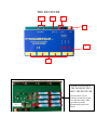
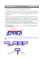
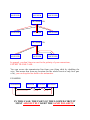
© Registered trademarks
DIGITAL COMMAND SYSTEM
FOR PYROTECHNICS & SPECIAL EFFECTS.
INSTRUCTIONS
5 and 7 / ARTS France
Tel +(33) (0)1 60 65 27 27. Fax +(33) (0)1 60 65 66 22
BP N°30068 / 77983 ST. FARGEAU. PTHIERRY CEDEX
Web site: www.arts-france.com
THE FIRING TABLE (Transmitter)
4
1
2
3
6
7
To use the device with LR6type batteries, please use the
8 first battery locations.
To use the device with
reloadable NiMh-type
batteries, it is highly
recommended to add 2 more
batteries. In that case, you
have to unweld the “+” pole
on the lower part of the PCB
and to weld it on the “NiMh
+” position marked on the
PCB.
5
THE RECEIVER
11
10
12
9
14
A
N°5
B
C
N°2
N°1
13
HOW TO INSTALL
THE INNER SUPPLY
INTO THE RECEIVER
Unscrew the 4 screws
located on each side of the
case and insert the 8 LR6type batteries in the
appropriated position as
shown.
The Connection of the lines
(Power Station)
19
16
15
18
17
The “PYRODIGITAL” system has been designed by professionals for
professionals. Indeed, professional pyrotechnists and experts in specials effects
designed this system to help you to face up to the difficulties you may meet on
the field. "PYRODIGITAL will provide you with much more possibilities on the
field when designing your fireworks.
This device will help you to make your fire arrangement easier: the wiring is
simplified, and there are neither more multipaired cables nor dispatching boards.
1) HOW DOES YOUR “PYRODIGITAL” SYSTEM WORK?
The system always consists of three parts:
1) The transmitter called the “FIRING TABLE”;
2) One or several receivers “RECEIVER” on which you’re going to connect
3) One or several line-switchboard(s), the “POWER STATION”.
The transmitting/receiving system is able to manage 8 x 120 independent
outputs. This means that your firing table and the 8 receiver(s) can continuously
manage 8 X 120 firing lines (up to 30 lines for each of the 4 power-stations
(named A to D) connected to the receivers, i.e. 30 X 4 = 120 max per receiver).
On each receiver, you’re going to plug the line-switchboard(s) for each group of
30 lines you need, i.e. from 1 to 4 power stations.
On each power-station, it is strongly recommended to name your lines as
follows: lines 1 to 30 should be renamed A1 to A30; lines 31 to 60 should be
renamed B1 to B30, and so on until the line number 120 which becomes the
number D30.
It may happen that the same firing line will be distributed towards several points
on the field and therefore it will be managed by several receivers. That’s why
your firing line must always be connected under the same number of ignition
order. Wherever you are on the field, an A10 line must always be linked onto
the connector Nbr 10 on a switchboard belonging to the A receiver group.
The safety firing system used here is a "dual-press" system: you must press
down simultaneously the button named “group” (i.e. A, B, C or D) and the
button corresponding to the number of the firing line.
2) THE CONNECTIONS:
A) Connections between the Firing Table and the Receivers.
You can choose any bifilar wire you want to achieve the connections between
the firing table and the receivers. (Note: a wireless HF connection system is
available in option). There is no use working with shielded cables or any other
special cables.
You can use the wire you want (minimum S=0,50 mm²) but remember that, on
the field, the global strength to shocks, to burns (falling-back) or to any other
problem will be directly linked to the own strength of the wire you have chosen.
A strong bifilar and non flammable wire will protect you much better from the
cut-off hazards and therefore from the interruption of the launching
To the 8 outputs of the firing table, you’re going to connect the numbers of
receivers you need (maximum 9 receivers if you want to use the “link-test”, see
hereafter page 8).
This wiring can be done almost as you want but ALWAYS IN PARALLEL
and NEVER SERIES.
NEVER THIS
TRANSMITTER
RECEIVERS
ALL THE FOLLOWING ELECTRICAL WIRINGS ARE ALL RIGHT
Ð
TRANSMITTER
RECEIVER
RECEIVER
TRANSMITTER
RECEIVER
RECEIVER
RECEIVER
RECEIVER
TRANSMITTER
RECEIVER
RECEIVER
RECEIVER
TRANSMITTER
RECEIVER
RECEIVER
RECEIVER
In general, you don’t have to care for the polarity of your connections,
EXCEPT IN ONE CASE:
You can secure the transmission line from your firing table by doubling the
wire. That means that from any location (for the whole circuit or only for a part
of it), you can loop the line back to the transmitter.
EXAMPLE:
TRANSMITTER
RECEIVER
RECEIVER
RECEIVER
IN THIS CASE, THE PART OF THE LOOPED CIRCUIT
MUST ABSOLUTELY KEEP THE SAME POLARITY.
B) Connection of the fireworks lines on the line-switchboard “Power
Station”
As usual, you connect each of your lines with one wire to the matching
connector, corresponding to its firing number (Nbr 16) and the other wire to the
common output (Nbr 17).
BE CAREFUL: connect to one of the two Common Outputs (Nbr 16) ONLY
the lines belonging to the same group (all lines from the A group must be
connected to the A Common output, those belonging to the B group must be
connected to the B common output and so on…)
The fireworks lines must be connected in series, NEVER IN PARALLEL.
3) DESCRIPTION OF THE COMMANDS FOR THE
DIFFERENT PARTS OF THE SYSTEM:
A) The Transmitter (FIRING TABLE)
The transmitter consists of:
Two push-buttons:
- The upper button (Nbr 1). Named “1/0”. Put it in the right position to shut the
system down. Put it in the left position, to supply the lines with power.
- The lower button (Nbr 2). Named “Line / Battery”. In the right position and
with button Nbr 1 in its left position, it allows testing the inner batteries of
the Firing Table. Put it in the left position to supply the lines with power.
- When you want to fire your system, both buttons must be in their left
positions.
- When you want to shut down your system, both buttons must be in their right
positions.
One Micro-Ammeter located in the middle (Nbr 3):
See paragraph “Testing” hereafter.
One selector knob: (Nbr 4): eight positions numbered from 1 to 8. It allows
selecting the receiver that will fire a group of 120 lines among the 8 x 120 lines.
Sixteen connectors: (Nbr 5): numbered from 1 to 8. They are the outputs for
the 120 lines from the group you selected with the selector knob (Nbr 4).
Thirty press-buttons: (Nbr 6)
Numbered from 1 to 30: each one is used to set on fire the corresponding line
number (remember to press simultaneously the button (A to D) for the group).
Four buttons "group": (Nbr 7)
Called A to D: each one is used to select the group you want to fire.
TESTS:
Connection Test:
One visual indicator for the transmission test (located on the left of button
Nbr 2).
By pressing down a “GROUP” button (A, B, C or D), if the visual indicator is
on, it shows that the transmitter is working (i.e. sending its signals).
Inner Supply Test:
Power the transmitter on (12V voltage). Put the upper button (Nbr 1) into the
left position (POWER ON), put the lower button (Nbr 2) into the right position
(BAT.). The Micro-Ammeter gives you the level of charge of the batteries (i.e.
the inner supply of the transmitter): the result is given in percentage. A
minimum of 80% is required for the transmitter to operate properly.
Receiver Link Test:
Keep the transmitter supplied (12 V). Put the upper button (Nbr 1) into the left
position AND the lower button (Nbr 2) into the left position (LINE ON): you are
now ready to fire, but you can also make some more tests:
TESTS:
Keep the two buttons into their left position and keep the firing table supplied.
While pressing down ONLY a “GROUP” (Nbr 7) button:
A) If the needle of the Micro-Ammeter (Nbr 3) immediately goes up to
the maximum (i.e.100), this means that the link between the firing table and the
receiver(s) is in short circuit. You need to check your installation (and to repair
it).
B) If the needle of the Micro-Ammeter (Nbr 3) goes up to 10µA, 20µA,
30µA, and so on, it gives you the number of receivers connected to your firing
table (10µA per receiver). (Be careful, this result is obtained whether your
receivers are powered or not. This test gives you only the quality of the line
towards your receivers.)
For example, if you have three receivers connected on the field, your MicroAmmeter should indicate 30µA. (Note that according to the ambient air
humidity or even the surface dampness of your wires, this value may be slightly
higher).
That’s why, if you use more than 9 receivers on the field, you cannot use this
test anymore. (However, the system is able to deal with up to 20 receivers per
group).
FIRE POSITION:
Keep the receiver powered, put both buttons in their left position, the ignition is
only possible by a “dual-press” of two distinct keys (safety measure).
To set on fire your firework lines, you need to press simultaneously the
corresponding “group” key (Nbr 7) AND one of the keys corresponding to a line
number (Nbr 6). (Be careful not to press at the same time two firework lines or
two “groups” keys).
In order to obtain a repetition effect, keep one of your fingers pressed on the
“group” button and press quickly one after the other the “line numbers” keys
(slip your finger on them).
Repeat this operation for each group of 120 lines (Nbr 4 and 5) that you want to
use.
B) THE RECEIVER:
Put the inner batteries into the receiver (8 LR6-type batteries, not furbished). see
photograph on page 3.
Close the battery case, check the good voltage of your supply with a voltmeter
by using the two test points (Nbr 11), named “Batteries Internal Test 12V”.
Please, check regularly the batteries voltage supply, especially before launching
the fire.
Do not keep the batteries inside the device in case of prolonged non-utilization.
The receiver consists of:
One 2-poles connector: (Nbr 9)
Located on the right of the device and named “LINE IN”. It is used to connect
the line with the transmitter and the other receivers (remember: be careful with
the polarity when there is a loop).
One two-position push button with power light indicator (Nbr 10):
- Button in its upper position (READY TO FIRE): the device is ready for the
fire. It supplies energy for the lines.
- Button in its lower position (OFF + TEST): the receiver is switched off and
the line test is available.
(see hereafter, how to use the line test)
Two 4 mm-female-plugs “+” and “-“ (Nbr 12) named “POWER”
These plugs supply the current that is going to set on fire the ignition starters of
your fireworks lines.
You can adapt the voltage to the real voltage needed by your lines.
BE CAREFUL: always work with DC current and don’t forget to respect
and check the polarities of your circuit.
The European Standards limit the DC-voltage to 48V. We have secured this
device and you may use it up to 100Vcc without any safety problem.
NEVER CONNECT THESE SUPPLIES DIRECTLY TO THE MAINS!
We advise you to use our supply-suitcases with these receivers.
Four female SUB-D plugs (DB25-type): (Nbr 13):
These 4 plugs are used to connect the line-switchboards.
Each plug (A, B, C, or D) corresponds to the same group on the transmitter.
CAUTION: Connect the cord connectors carefully into the pendant plugs, and make sure they
are well screwed onto the case.
The damage of one of the male plugs (from a line-switchboard) always comes from a bad
handling. Please note that this problem is not included in the warranty. You may have it
changed at any qualified hi-fi, computer or TV shop or after-sale service.
Three visual indicators located on the right (Nbr 14).
From the left to the right, you can find:
A) BAT 12V: This indicator shows that the receiver is powered (inner batteries
voltage = OK).
B) POWER: This indicator shows that the external supply is powered (external
batteries = OK).
C) SIGNAL: This indicator is used when making another link-test with the
transmitter. When a button "GROUP" is pressed on the transmitter, this indicator
lights up and indicates that the signals are well transmitted to the receiver. To
perform this test, the receiver doesn't need to be powered. Note that this is not a
test to check the launching.
The receiver is ready to set fire when both indicators (A and B) are lit.
C) THE LINE-SWITCHBOARD (POWER STATION):
The line-switchboard consists of:
One female Sub D plug (DB25-type) (Nbr 15)
Connect the power station to the receiver (Nbr 13), using the SUB-D cable
supplied.
Make sure to connect it in the group to which it belongs.
Thirty connectors (Nbr 16)
They are numbered from 1 to 30. On each connector, you have to connect the
wire coming from a firework line.
Two “COMMON OUTPUT” connectors. (Nbr 17).
All the second wires coming from your lines must be connected to these
“Common Outputs”. (Connect only the wires belonging to the A, B C or D
group to which it is linked).
CAUTION: Never connect the supply source for the battery directly to this
common output.
One test push-button (Nbr 18) (LINE TEST) and 30 test LEDs (Nbr 19).
This test allows you to check the good connection of your lines.
To run this test, put the two-position push button (Nbr 10 on the receiver) into
the “OFF + TEST" position.
By pressing the “TEST” push-button (Nbr 18) located on the left face of the
Power station, you can check if the lines are well connected: if the lines are
correctly connected (in series) the corresponding LEDs highlighted.
4) IT IS READY FOR THE FIRE
1) Your transmission lines (on the firing table) between the transmitter and the
receiver are well connected (test done on the transmitter).
2) Your different electric supplies are operational (they have been checked with
the "BATTERY TESTER").
3) The receivers are powered for both supplies (electric parts connected and
push button in the "READY TO FIRE" position).
The receivers do not require much energy. You can power them several
hours before launching. But don't forget the safety system. As soon as the
receivers are powered, be careful that no one can give an inopportune firing
order from the transmitter. In order to avoid such a problem, make sure to
power on the transmitter only at the very last moment.
4) The DB25-type connectors are well plugged and screwed onto the receiver’s
case.
5) Power on the transmitter and… have a nice moment!
5) SOME ADVICE
"PYRODIGITAL”, like any electronic device, is not designed to withstand high
ambient air humidity. Protect it the best you can by using a well adapted
packaging.
On the field, at the different points where you put the receivers, you will find a
set of receiver + line-switchboard(s) + electric supplies. We advise you to wrap
the whole set of devices into a huge transparent plastic bag that will protect them
all at the same time. This will also protect the electronic material even in case of
bad weather and keep the wires connected without any problem. The big plastic
bag will also allow you to handle all the powering buttons and the test buttons to
check the lines without any trouble.
Protect the transmitter and its power supply against rain and humidity by closing
the suitcase when not using it.
On the Power Station please take a special care about the DB25-type link cable.
Don't move these switchboards by holding them by their wires. Don't pull this
cable!
ON ALL THE FOLLOWING CONNECTORS (NBR 5 ON THE FIRING TABLE, NBR 9 ON THE
RECEIVER AND ESPECIALLY NBR 16 ON THE POWER STATION, THE CONNECTIONS
TOWARDS THE LINES), ONLY DISMANTLE 5MM MAXIMUM OF THE WIRE.
Check that the uninsulated parts of the wires cannot reach the wires around or
even touch any metallic part of the system.
"PYRODIGITAL”, like any electronic device, is not designed to withstand
shocks. Protect it during transportation. Don't throw it into your truck like you
would do with a mortar!
All parts of our system do have a number. This number is your guarantee.
All our devices are referenced and in case of return in our after-sales services,
we check that the person who is asking for a repair is the owner.
Don’t forget to send us back your warrantee sheet to validate both our
guarantees and the possible maintenance of your devices.
In this sheet, you must approve our selling and guarantee policies, and you must
also indicate the references of your devices.
In case of resale of your equipment, please ask the new owner to contact us. For
your safety, we don't repair any material of unknown origin.
IMPORTANT WARNING
Most of the lines bad ignitions are due to the bad quality of the batteries that
supply these lines.
We advise you to check them regularly (check them in DISCHARGING
position and not off-load with a simple voltmeter).
For that case, we have specially designed a "PYRONUMERIC BATTERY
TESTER” that indicates precisely which amount of current the generator will
surge to put your lines on fire.
Thus, connected side by side with your voltmeter, you will exactly know the real
capacity of your batteries.
Only the "PYRONUMERIC BATTERY TESTER” can give you this major
information.
Characteristics of the keyboard on the transmitter.
Supply voltage: 12V DC +/- 2V.
Do not exceed 15V DC maximum voltage to prevent from destruction.
Line Current: 40mA for 8 receivers maximum
Short-circuit current: 100mA
Be careful not to keep this short-circuit current more than 30s. This is to limit the
warming-up of the supply inside the keyboard.
A command is issued when:
The button is its “POWER ON” position
The button is its “LINE ON” position
Press simultaneously one out of the four keys “Group” (A to D) and one out
the 30 line-buttons (numbered from 1 to 30)
Line Test: when pressing on the A group key, the galvanometer must indicate 10µA
per receiver connected.
Characteristics of the receiver:
Supply voltage: 12V DC +/-2V.
Do not exceed 15V DC maximum voltage to prevent from destruction.
Incoming Line current: 5 mA, non polarized connections.
Do not exceed 15V DC maximum voltage to prevent from destruction.
Voltage power (Power): 48V DC max
Protected by a 2A internal fuse (model “fast glass 5x20”).
Output power: 1A current generator.
Be careful not to maintain this short-circuit current more than 5s. This is to limit the
warming-up of the internal supply in the module. (The shut down command on the
keyboard cancels this current).
The line voltage attenuation equals 1V by ohm of line (1V/Ω).
Output commands for the relay: 50mA current generator.
4 outputs of 30 relays each, on 4 DB25-type plugs named A to D (groups).
The system is ready to be powered when:
Characteristics of the relay module (line-switchboard):
30 outputs with 30 visual displays DEL.
Test button to check the lines.
This button is in function when pressed and:
Button on the receiver put in its “OFF + TEST” position
Visual display highlighted if the line is OK.
Visual display off if the line is cut off.
The system is ready to be powered when:
Button on the receiver is its “READY TO FIRE” position
The Common Output distributes the negative signal from the POWER (48V max
under 1A)
The back positive signal from the POWER is handled through the 30 lineswitchboard.
The command is transmitted thanks to electromagnetic relays.
SAFETY MEASURES AND GENERAL TERMS OF GUARANTEE.
1) SAFETY MEASURES
The PYRODIGITAL system is a professional material designed to manage fireworks
or pyrotechnic effects.
The purchaser certifies being a professional. He/she engages himself/herself to make
sure that only specially trained and certified people will use this material (K4 license
or equivalent). If not, the purchaser will have in charge to train these people to this
new fireworks system.
In the case where the purchaser or the user would not be familiar at all (or not
sufficiently familiar) with the use of this fireworks system, he acknowledges not to use
it before getting from the manufacturer all safety and technical advice necessary to its
working.
Whatever the situation, the person in charge must take all precautions to protect
goods and people, as far as electromagnetic- or radio-perturbations are concerned.
(E.g. High Power Transmitter Antennas or Current Transformers in the vicinity,
stormy weather… and so on. Please note that this is a non-exhaustive list.)
Make sure to put the firing system under power only at the very last moment
(especially the high voltage for the line ignition.) If there’s any doubt left, the person
in charge must take all precautions to avoid any inopportune ignition of the system
(line coupling, disconnection of the linking lines …)
2) GENERAL TERMS OF GUARANTEE
Each part of the PYRODIGITAL system is guaranteed (pieces and labour) by the
manufacturer for a period of 12 consecutive months, due after the delivery date.
In order to validate this guarantee, it is MANDATORY for the customer to return the
specific documents delivered with each part of the PYRODIGITAL system and a
purchasing proof with the date of purchase (for example : duplicate of your invoice or
certificate from the seller). Each element has its own guarantee.
Limits of the guarantee:
TO THE EXCLUSION OF ALL OTHER REQUESTS:
The guarantee only covers the repair in the manufacturer’s workshop or the
replacement by an equivalent device of the defective part of the system (in the case
where the device could not be repaired).
The shipping costs must be paid by the customer.
No indemnity is due to the customer during the repairing period where the system
might be kept by the manufacturer.
Although the system may be repaired or replaced, the initial warranty period is
neither extended nor renewed.
By putting his signature on the sales contract, the customer declares being a
professional. He certifies having the skills to anticipate any breakdown of the system
before or during the fireworks launch.
Therefore, he certifies also that he will not claim for any compensation or indemnity
for a show that would have been partly or totally spoiled by a bad functioning of the
"PYRODIGITAL / PYRONUMERIC" system.
NO GUARANTEE IS DUE WHEN:
- The breakdown is linked to a bad use of the system, not conform to the instruction
manual.
- The device has been opened or dismantled by a non-authorized person (i.e.
someone that has not been authorized to work on the device by the
manufacturer).
- The device has not been correctly maintained or has been badly stored (waterdamage, shock or negligence for example).
- The purchasing vouchers have been modified or altered.
- The serial number inside the device is no longer recognizable.
- The payment conditions between the purchaser and the seller are not respected
(no payment or too long delay of payment) even if the manufacturer is not the
seller.
In case of litigation, the involved parts agree to recognize the competence of the
Court located in the town of the manufacturer's head office.