1
Technical Information
SMA SPEEDWIRE FIELDBUS
Speedwire-TI-en-11 | Version 1.1
ENGLISH
SMA Solar Technology AG
Table of Contents
Table of Contents
1 Information on this Document. . . . . . . . . . . . . . . . . . . . . . . . . . . 5
2 Introduction. . . . . . . . . . . . . . . . . . . . . . . . . . . . . . . . . . . . . . . . . . 7
2.1
2.2
2.3
2.4
What is Speedwire? . . . . . . . . . . . . . . . . . . . . . . . . . . . . . . . . . . . . . .
Speedwire Products . . . . . . . . . . . . . . . . . . . . . . . . . . . . . . . . . . . . . . .
Skills of Qualified Persons . . . . . . . . . . . . . . . . . . . . . . . . . . . . . . . . . .
Safety Precautions . . . . . . . . . . . . . . . . . . . . . . . . . . . . . . . . . . . . . . . .
7
8
9
9
3 Speedwire Communication in PV Systems. . . . . . . . . . . . . . . . 10
3.1 Requirements for Using Speedwire . . . . . . . . . . . . . . . . . . . . . . . . . . 10
3.2 Requirements for Qualified Network Components . . . . . . . . . . . . . . 10
3.3 Speedwire Properties. . . . . . . . . . . . . . . . . . . . . . . . . . . . . . . . . . . . . 11
3.3.1 Data Transfer Rate . . . . . . . . . . . . . . . . . . . . . . . . . . . . . . . . . . . . . . 11
3.3.2 Maximum Line Lengths (End-to-End-Links). . . . . . . . . . . . . . . . . . . . . 11
3.3.3 Communication Protocols Used . . . . . . . . . . . . . . . . . . . . . . . . . . . . 11
3.3.4 Device Addressing and Device Detection . . . . . . . . . . . . . . . . . . . . 12
3.4 Cabling in the Speedwire Networks . . . . . . . . . . . . . . . . . . . . . . . . . 13
3.4.1 Cable Requirements . . . . . . . . . . . . . . . . . . . . . . . . . . . . . . . . . . . . . 13
3.4.1.1
General Information. . . . . . . . . . . . . . . . . . . . . . . . . . . . . . . . . . 13
3.4.1.2
Cable Categories. . . . . . . . . . . . . . . . . . . . . . . . . . . . . . . . . . . . 14
3.4.1.3
Cable Shielding . . . . . . . . . . . . . . . . . . . . . . . . . . . . . . . . . . . . . 15
3.4.1.4
Grounding . . . . . . . . . . . . . . . . . . . . . . . . . . . . . . . . . . . . . . . . . 16
3.4.1.5
Cable Sheath . . . . . . . . . . . . . . . . . . . . . . . . . . . . . . . . . . . . . . . 16
3.4.1.6
Cabling Plan. . . . . . . . . . . . . . . . . . . . . . . . . . . . . . . . . . . . . . . . 17
3.4.1.7
Cabling Recommendations . . . . . . . . . . . . . . . . . . . . . . . . . . . . 18
3.4.2 Network Terminal. . . . . . . . . . . . . . . . . . . . . . . . . . . . . . . . . . . . . . . 18
Technical Information
3.4.2.1
General Information. . . . . . . . . . . . . . . . . . . . . . . . . . . . . . . . . . 18
3.4.2.2
Terminal Assignment of Network Plugs . . . . . . . . . . . . . . . . . . . 19
3.4.2.3
Network Port LEDs . . . . . . . . . . . . . . . . . . . . . . . . . . . . . . . . . . . 20
3.4.2.4
Terminal Assignment Color Schemes . . . . . . . . . . . . . . . . . . . . . 21
3.4.2.5
Network Plug Connection . . . . . . . . . . . . . . . . . . . . . . . . . . . . . 22
Speedwire-TI-en-11
3
Table of Contents
SMA Solar Technology AG
4 Basics for Planning a PV System with Speedwire . . . . . . . . . . 23
4.1 Selecting the Topology . . . . . . . . . . . . . . . . . . . . . . . . . . . . . . . . . . . 23
4.1.1 Line Topology. . . . . . . . . . . . . . . . . . . . . . . . . . . . . . . . . . . . . . . . . . 23
4.1.2 Star Topology . . . . . . . . . . . . . . . . . . . . . . . . . . . . . . . . . . . . . . . . . 24
4.1.3 Tree Topology . . . . . . . . . . . . . . . . . . . . . . . . . . . . . . . . . . . . . . . . . 25
4.2 Information on Laying the Network Cables . . . . . . . . . . . . . . . . . . . . 26
4.2.1 General Information. . . . . . . . . . . . . . . . . . . . . . . . . . . . . . . . . . . . . 26
4.2.2 Information on Interference Suppression . . . . . . . . . . . . . . . . . . . . . 26
4.2.3 Mechanical Protection of Network Cables . . . . . . . . . . . . . . . . . . . 27
4.3 Checking the Speedwire Cabling . . . . . . . . . . . . . . . . . . . . . . . . . . . 27
5 Commissioning and Operation of a PV System with
Speedwire. . . . . . . . . . . . . . . . . . . . . . . . . . . . . . . . . . . . . . . . . . 29
6 FAQ . . . . . . . . . . . . . . . . . . . . . . . . . . . . . . . . . . . . . . . . . . . . . . . 31
7 Glossary . . . . . . . . . . . . . . . . . . . . . . . . . . . . . . . . . . . . . . . . . . . 32
4
Speedwire-TI-en-11
Technical Information
SMA Solar Technology AG
1 Information on this Document
1 Information on this Document
Target Group
This document is for qualified persons who are planning a PV system with SMA Speedwire devices
or intend installing one (see Section 2.3 "Skills of Qualified Persons", page 9).
Symbols
Symbol
%"/(&3
Explanation
Indicates a hazardous situation which, if not avoided, will result in death or
serious injury
8"3/*/( Indicates a hazardous situation which, if not avoided, can result in death or
serious injury
$"65*0/
Indicates a hazardous situation which, if not avoided, can result in minor or
moderate injury
/05*$&
Indicates a situation which, if not avoided, can result in property damage
Information that is important for a specific topic or goal, but is not
safety-relevant
☐
Indicates a requirement for meeting a specific goal
☑
Desired result
✖
A problem that might occur
Nomenclature
Complete designation
Designation in this document
SMA Speedwire Fieldbus
Speedwire
SMA Speedwire/Webconnect Piggy-Back
Speedwire/Webconnect Piggy-Back
SMA Speedwire/Webconnect data module
Speedwire/Webconnect data module
SMA Speedwire data module Sunny Island
Speedwire data module SI
SMA Webconnect function
Webconnect function
SMA inverter
Inverter
SMA Cluster Controller
Cluster Controller
Technical Information
Speedwire-TI-en-11
5
1 Information on this Document
SMA Solar Technology AG
Abbreviations
Abbreviation Designation
Explanation
AC
Alternating Current
‒
AWG
American Wire Gauge
US American coding system for wire
cross-section
DC
Direct Current
‒
DHCP
Dynamic Host Configuration Protocol
Protocol for the dynamic assignment of
IP configurations
ESS
Electronic Solar Switch
The Electronic Solar Switch and the
DC connectors form a DC load
disconnect unit
IP
Internet Protocol
‒
LAN
Local Area Network
‒
LED
Light-Emitting Diode
‒
OF
Optical Fiber
‒
PV
Photovoltaics
‒
WAN
Wide Area Network
‒
6
Speedwire-TI-en-11
Technical Information
SMA Solar Technology AG
2 Introduction
2 Introduction
2.1 What is Speedwire?
Speedwire is a wired, Ethernet based fieldbus for the implementation of powerful communication
networks in decentralized large-scale PV power plants.
Speedwire uses the internationally established Ethernet standard, the Ethernet based IP protocol as
well as the communication protocol SMAData2+ optimized for PV systems. This enables a consistent
10/100 Mbit data transmission to the inverter as well as reliable monitoring, control, and regulation
of the PV system.
The Speedwire network can be set up with the following optional topologies:
• Line topology (see Section 4.1.1, page 23)
• Star topology (see Section 4.1.2, page 24)
• Tree topology (see Section 4.1.3, page 25)
The Speedwire fieldbus consists of:
• Qualified network components such as network switches or network cables
(see Section 3.2 „Requirements for Qualified Network Components“, page 10 and
Section 3.4.1 „Cable Requirements“, page 13)
• Speedwire system components of SMA Solar Technology AG such as Cluster Controller,
Sunny Home Manager, SMA Energy Meter and inverters with Speedwire interface
(see Section 2.2 "Speedwire Products", page 8)
Technical Information
Speedwire-TI-en-11
7
2 Introduction
SMA Solar Technology AG
2.2 Speedwire Products
SMA Speedwire Interfaces
There are different Speedwire interfaces for SMA inverters:
• Speedwire integrated
– installed ex works
– depending on the inverter:
– Inverter has one network port (tree topology or star topology possible)
– Inverter has two network ports (line topology, tree topology or star topology possible)
– connection via plug & play
• Speedwire/Webconnect data module
– available as a retrofit kit or is pre-installed in the inverter
– has two network ports (line topology, tree topology or star topology possible)
– connection via plug & play
• Speedwire/Webconnect Piggy-Back
– available as retrofit kit
– has one network port (tree topology or star topology possible)
– connection via network cable
• Speedwire data module Sunny Island
– available as retrofit kit
– has one network port (only star topology possible)
– connection via plug & play
Supported SMA Speedwire Products
Inverters
All inverters with integrated or retrofitted Speedwire interface.
Information on whether an inverter has an integrated Speedwire interface or can be retrofitted with a
Speedwire interface can be found on the product page of the respective inverter at
www.SMA-Solar.com.
Communication Products (Devices and Software)
Information on whether a communication product supports Speedwire can be found on the product
page of the respective communication product at www.SMA-Solar.com.
8
Speedwire-TI-en-11
Technical Information
SMA Solar Technology AG
2 Introduction
2.3 Skills of Qualified Persons
The tasks described in this document must be performed by qualified persons only. Qualified persons
must have the following skills:
• Training in the installation and commissioning of electrical devices and systems
• Knowledge of how to deal with the dangers and risks associated with installing and using
electrical devices and systems
• Knowledge of how an inverter works and is operated
• Knowledge of all applicable standards and directives such as EN 50173-1, EN 50173-3,
EN 60950-1, ISO/IEC 11801, ANSI/TIA 568-C.2
• Knowledge of Ethernet network engineering
• Knowledge of and adherence to this document and all safety precautions
2.4 Safety Precautions
For the connection of the network cables to the Speedwire interfaces of the inverter, the inverter must
be opened. Observe all safety precautions in the installation manual of the respective inverter as well
as the following safety precautions for working safely on the inverters.
%"/(&3
Danger to life due to electric shock when opening the inverter
High voltages are present in the conductive components of the inverter. Touching live components
results in death or serious injury.
• Prior to performing any work on the inverter, always disconnect the inverter from all voltage
sources on the AC and DC sides (see inverter installation manual). Observe the waiting time
to allow the capacitors to discharge.
$"65*0/
Risk of burns due to hot enclosure parts
Some parts of the inverter enclosure can get hot during operation. Touching these enclosure parts
can result in burn injuries.
• Do not touch any parts other than the lower enclosure lid of the inverter during operation.
/05*$&
Damage to the inverter due to electrostatic discharge
The internal components of the inverter can be irreparably damaged by electrostatic discharge.
• Ground yourself before touching any inverter component.
Technical Information
Speedwire-TI-en-11
9
3 Speedwire Communication in PV Systems
SMA Solar Technology AG
3 Speedwire Communication in PV Systems
3.1 Requirements for Using Speedwire
You need the following components to be able to use Speedwire:
• at least one inverter that is equipped with one Speedwire interface (see Section 2.2 "Speedwire
Products", page 8)
• one Speedwire-enabled communication product (see Section 2.2 "Speedwire Products", page 8)
• one computer
The network cabling of the PV system must be carried out in accordance with the requirements
(see Section 3.4, page 13) described in this document.
3.2 Requirements for Qualified Network Components
You can use standard network components for Speedwire. However, the following minimum
requirements must be fulfilled.
Requirements:
☐ Data transfer rate Fast Ethernet (10BASE-T/100BASE-TX) or Gigabit Ethernet (1000BASE-T)*
☐ Support of autonegotiation **
☐ Support of autocrossing
☐ Support of the data transfer procedure full duplex
☐ Network connection technology RJ45 with shield connection
☐ At least two network ports for realization of a line topology; for line topology end users one
network port or one network connection is sufficient.
☐ The MAC address storage of the network switches used must have at least 512 MAC address
entries each and be sufficient for the PV system size planned.
☐ Router or network switches that are used outdoors, must have degree of protection IP65.
* Each gigabit interface has 10BASE-T/100BASE-TX/1000BASE-T and is thus downward compatible to Fast Ethernet
(10BASE-T/100BASE-TX).
** Autonegotiation (also "auto-sensing"): automatic setting of the fastest possible speed that is supported by both link partners.
10
Speedwire-TI-en-11
Technical Information
SMA Solar Technology AG
3 Speedwire Communication in PV Systems
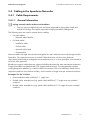
3.3 Speedwire Properties
3.3.1 Data Transfer Rate
Speedwire is designed as a fieldbus for PV system communication for a data transfer rate of
100 Mbit/s. This data transfer rate is also supported by network components with the designation
"10/100Mbit/s".
All Speedwire devices use two transfer standards:
• 10BASE-T (10 Mbit/s)
• 100BASE-TX (100 Mbit/s)
The data transfer rate is automatically adjusted by all Speedwire devices. 100 Mbit/s with full duplex
is selected as standard.
3.3.2 Maximum Line Lengths (End-to-End-Links)
The maximum line length between two nodes is also called "end-to-end-link". The maximum length of
the end-to-end-link depends on the cable type used:
• When using installation cables (e.g. Profinet cables) and a maximum of two interfaces*: 100 m
at maximum
• When using patch cables: maximum of 50 m
The maximum total length of the Speedwire fieldbus depends on the end-to-end-link and the number
of devices allowed per communication product.
Example: maximum total length for PV systems with Cluster Controller
Cluster Controller can only manage a maximum of 75 inverters. The end-to-end-link between the
nodes (Cluster Controller, inverter) is 100 m each.
75 x 100 m = 7,500 m
Thus, the maximum total length is 7,500 m.
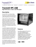
3.3.3 Communication Protocols Used
The Internet protocol v4 (IPv4) is used as a communication protocol (OSI level 3). The user datagram
protocol (UDP) is used as a transport protocol (OSI level 4). SMA Data 2+ telegrams are transmitted
in the UDP/IP data frame.
Figure 1:
Design of the Speedwire communication protocol
* A coupling device or a network connection box can be used as an interface.
Technical Information
Speedwire-TI-en-11
11
3 Speedwire Communication in PV Systems
SMA Solar Technology AG
3.3.4 Device Addressing and Device Detection
Device Addressing
When using the internet protocol it is necessary for each node to receive a unique IP address in the
respective subnetwork. The IP address can be assigned in various ways:
• If there is no DHCP server in the Speedwire network, the IP addresses are assigned
automatically among the nodes by means of the IPv4LL protocol.
• If there is a DHCP server in the Speedwire network (e.g. Cluster Controller or router),
all IP addresses can be assigned by the DHCP server.
• If necessary, the IP addresses can also be assigned statically, for example by means of the
SMA Connection Assist* or via the respective communication device (e.g. Cluster Controller).
Device Detection
Depending on the SMA products used, device detection can take place automatically via a
communication product (e.g. Cluster Controller) or via software (Sunny Explorer or SMA Connection
Assist) (see manual of the SMA product).
* You can obtain the Sunny Explorer and SMA Connection Assist software free of charge from the download area at
www.SMA-Solar.com.
12
Speedwire-TI-en-11
Technical Information
SMA Solar Technology AG
3 Speedwire Communication in PV Systems
3.4 Cabling in the Speedwire Networks
3.4.1 Cable Requirements
3.4.1.1 General Information
Laying network cables indoors and outdoors
• Only use network cables that have each been approved for laying them inside and
outside of buildings. This applies especially to laying the cables underground.
The following terms are used in network device cabling:
• For patch cables:
– Network cable, flexible
• For fixed cables:
– Installation cable
– Profinet cable
– Network cable, fixed
– Permanent link
Network cables with eight wires that are arranged in four pairs with two wires each are approved for
Speedwire. The respective wire pair is twisted. Cables that have only four wires (minimum
requirement) and are either arranged in two twisted wire pairs or in a star quad (four wires twisted at
once) are also approved.
Besides pure copper cables there are copper-clad cables that have the same transmission properties.
Copper-clad cables are labeled with CCA (copper-clad aluminum). The internationally common
coding designation AWGxx/y is used for cable cross-sections. The xx in AWGxx/y stands for the
respective conductor cross-section and the y for the number of single wires per insulated conductor.
Examples for the Y Values
• Fixed installation cable: AWGxx/1: 1 single wire
• Flexible cable, stranded wire (e.g. patch cable): AWGxx/7: 7 single wires per insulated
conductor
• Flexible cable, stranded wire (e.g. patch cable): AWGxx/19: 19 single wires per insulated
conductor
Technical Information
Speedwire-TI-en-11
13
3 Speedwire Communication in PV Systems
SMA Solar Technology AG
The following conductor cross-sections (xx) are typically used for Ethernet and Speedwire
cabling:
• Solid conductor: AWGxx/1; AWG26 to AWG22 (AWG26 to AWG22 corresponds to a
conductor cross-section of 0.13 mm2 to 0.32 mm2)
• Flexible cable, stranded wire (e.g. patch cable): AWGxx/7; AWG26 to AWG22
(AWG26 to AWG22 corresponds to a conductor cross-section of 0.13 mm2 to 0.32 mm2)
• Example of a standard patch cable: AWG26/7 (7 single wires with 0.13 mm2 cross-section)
The term xxAWG is also used for some network cables. Installation cables are also referred to as
"AWG24 fixed" (equals AWG24/1).
3.4.1.2 Cable Categories
Profinet cable types can be used in addition to eight-wire standard network cables for Speedwire.
In European standardization cables are also categorized by classes, but commonly in categories.
("Cat" = "category"). This category determines which data transfer rate is possible at most with the
respective network cable.
The following table shows which category network cables must have for Speedwire.
Features/
Properties
Category
Cat3
Cat5, Cat5e
Cat6, Cat6a
Cat7
C
D
E
F
Up to 10 Mbit/s
Up to
10/100 Mbit
and gigabit
Up to 1 gigabit
and 10 gigabit
Up to 10 gigabit
Class
Speedwire
approval
Data transmission
rate
Symbols used:
14
= approved;
Speedwire-TI-en-11
= not approved
Technical Information
SMA Solar Technology AG
3 Speedwire Communication in PV Systems
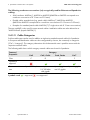
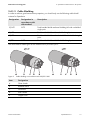
3.4.1.3 Cable Shielding
In order to achieve good transmission properties, you should only use the following cable shield
variants for Speedwire.
Designation
Designation in
accordance with
old standard
Description
SF/UTP
S-FTP
Total braided shields and total shielding foil with unshielded
single pairs
S/UTP
−
Total braided shields with unshielded single pairs
SF/FTP
−
Total braided shields and total shield foil with shielded single
pairs
S/FTP
S-STP
Total braided shields with foil shielded single pairs
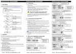
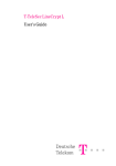
The most common cable types on the market are SF/UTP and S/FTP.
Figure 2:
Cable shielding in accordance with ISO/IEC11801
Item
Designation
A
Outer sheath
B
Braided shield
C
Foil shield
D
Inner sheath
E
Copper wire
Technical Information
Speedwire-TI-en-11
15
3 Speedwire Communication in PV Systems
SMA Solar Technology AG
3.4.1.4 Grounding
For Speedwire devices the cable shield is usually grounded via the respective network port. The cable
shield must always be positioned at the network plug. No additional grounding measures are
necessary. Only for Speedwire/Webconnect Piggy-Back does the grounding of the cable shield take
place via the connection to the shield clamp in the inverter (see Speedwire/Webconnect Piggy-Back
installation manual).
3.4.1.5 Cable Sheath
The cable laying site determines the outer sheath cable material. Network cables are available for
the following areas:
• Indoor routing
• Outdoor routing
• Underground installation
Network cables are available for each area with the corresponding properties. The most important
cable properties are printed on the cable sheath for identifying the network cable.
Examples: imprint cable sheath and cable properties
Imprint
Cable properties
SFTP 300 CAT.5E 26AWGX4P PATCH
ISO/IEC11801 & EN50173 verified
• S/FTP, braided shield, CAT5e performance
• AWG26 cable with four twisted wire pairs as patch
cable
• Tested in accordance with standards
ISO/IEC11801 and EN50173
• Patch cable, only for short distances
Cat5e SF/UTP patch cable
• Cable suitable for Fast Ethernet Cat5e
• Total braided shields and total foil shields for all
SF/UTP pairs
• Patch cable, only for short distances
S-FTP 4x2xAWG 24/1 CAT5e
• Total braided shields for all pairs and foil shields for
the single S/FTP pairs
• Installation cable for permanent link, cable fixed
• 4 double wires
16
Speedwire-TI-en-11
Technical Information
SMA Solar Technology AG
3 Speedwire Communication in PV Systems
3.4.1.6 Cabling Plan
Speedwire based on point-to-point connection from device to device. Tapping, single feeders, and
parallel use are not allowed. Speedwire devices can be cabled in accordance with two principles:
• Structured cabling for house and office installations
• Application-neutral PV system cabling for industrial locations
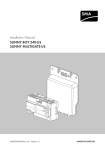
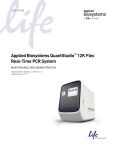
Direct Connection without Interface with Two Network Plugs
Figure 3:
Direct connection principle
A direct connection is favorable if the network cable is being laid directly and adjusted to the
end-to-end-link length.
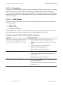
Connection with Interfaces
Figure 4:
Connection with two interfaces in accordance with the structured cabling principle (example)
The structured cabling requires an installation cable with a maximum length of 90 m. When
connecting Speedwire devices via interfaces, 5 m of patch cable should be planned for on both sides.
A maximum of two interfaces may be used in an end-to-end-link with a total length of 100 m.
Only a few interfaces should be utilized to prevent additional sources of disturbance. If more
interfaces are needed, the maximum length of the end-to-end-link is reduced. For each additional
interface that exceeds the maximum number of two interfaces per 100 m, the total length of the
network cable must be shortened by approximately 4 m.
Influence of high ambient temperatures on the maximum cable length
The maximum cable length in accordance with the standards of the structured cabling must be
reduced at high ambient temperatures.
Technical Information
Speedwire-TI-en-11
17
3 Speedwire Communication in PV Systems
SMA Solar Technology AG
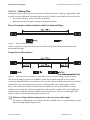
Use of Optical Fibers
If optical fibers are used besides copper cables in Speedwire networks, corresponding media
converters must be used.
Figure 5:
Use of media converters when using optical fibers
More information concerning the specifics when using optical fibers can be found in the respective
standards (see Section 2.3 "Skills of Qualified Persons", page 9).
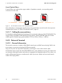
3.4.1.7 Cabling Recommendations
For Speedwire cabling SMA Solar Technology AG recommends cable type SMA COMCAB-OUT for
laying outdoors and SMA COMCAB-IN for laying indoors. SMA COMCAB cables are Profinet
cables type B for flexible laying and available in 100 m, 200 m, 500 m or 1,000 m.
3.4.2 Network Terminal
3.4.2.1 General Information
The network connection is made via RJ45 (RJ45 network port and RJ45 network plug). RJ45 is the
most common connection technology for Ethernet networks.
Only two line pairs are required for Speedwire, meaning four wires of the network cable.
All Speedwire ports support the Auto MDI/MDIX function, also called auto-crossing. This means that
an automatic switching of sender and receiver is integrated in all Speedwire devices. Thus, there is no
need to differentiate between crossed network cables (crossover cables) and uncrossed network
cables when laying cables.
18
Speedwire-TI-en-11
Technical Information
SMA Solar Technology AG
3 Speedwire Communication in PV Systems
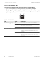
3.4.2.2 Terminal Assignment of Network Plugs
Figure 6:
Contact pin assignment network plug
Contact pin of the network
plug (RJ45)
Fast Ethernet MDI
assignment
Fast Ethernet MDI-X
assignment
1
TX+
RX+
2
TX −
RX −
3
RX+
TX+
4
Not assigned
Not assigned
5
Not assigned
Not assigned
6
RX −
TX −
7
Not assigned
Not assigned
8
Not assigned
Not assigned
Shield connection
Cable shield
Cable shield
Technical Information
Speedwire-TI-en-11
19
3 Speedwire Communication in PV Systems
SMA Solar Technology AG
3.4.2.3 Network Port LEDs
Colors and functionality of the network port LEDs are not standardized
Colors and functionalities of the network port LEDs are not consistently standardized.
The colors "green" for the link/activity LED and "yellow" for the speed LED used by
SMA Solar Technology AG as well as the respective functionalities might deviate when supplied
by third-party manufacturers.
Figure 7:
Network port LEDs
LED
Status
Explanation
A - link/activity (green)
off
No network connection has been established.
flashing
Network connection established
Data is being sent or received.
B - speed (yellow)
on
Network connection established
off
Network connection established
10 Mbit/s mode; the data transfer rate is up to
10 Mbit/s.
on
Network connection established
100 Mbit/s mode; the data transfer rate is up to
100 Mbit/s.
20
Speedwire-TI-en-11
Technical Information
SMA Solar Technology AG
3 Speedwire Communication in PV Systems
3.4.2.4 Terminal Assignment Color Schemes
The terminal assignment of the network cables is made in accordance with the standards
ANSI/TIA-568-A or ANSI/TIA-568-B. If a Profinet cable such as SMA COMCAB is used, the
assignment is based on Profinet's color scheme.
Speedwire requires two pairs as a minimum, meaning four conductors. The following table shows the
terminal assignment and the respective color scheme.
Network
plug contact
pin (RJ45)
Terminal
Color scheme for Color scheme for Color scheme for
assignment Fast eight-wire cables eight-wire cables four-wire cables
Ethernet
in accordance
in accordance
(Profinet)
with
with
ANSI/TIA-568-A ANSI/TIA-568-B
1
TX+
white/green
white/orange
yellow
2
TX
green
orange
orange
3
RX+
white/orange
white/green
white
4
Not assigned
blue
blue
−
5
Not assigned
white/blue
white/blue
−
6
RX −
orange
green
blue
7
Not assigned
white/brown
white/brown
−
8
Not assigned
brown
brown
−
Shield
connection
Cable shield
Cable shield
Cable shield
Cable shield
Four-wire cables are approved for Speedwire assignments of the network plugs in accordance with
ANSI/TIA-568-A and ANSI/TIA-568-B. It is important that both cable ends are wired in accordance
with the same industry standard. Observe the Profinet specification when using four-wire Profinet
cables. This also applies to pre-assembled cables.
Technical Information
Speedwire-TI-en-11
21
3 Speedwire Communication in PV Systems
SMA Solar Technology AG
3.4.2.5 Network Plug Connection
Network plugs of the categories Cat5, Cat5e, Cat6 and Cat6A can be used for Speedwire
("Cat" = "category"). The category determines which data transfer rate is possible at maximum with
the respective network plug.
Cat7 network plugs (also called "GG-45") are not approved since they are not downward
compatible and use another pin assignment.
Connect all insulated conductors for RJ45 connection.
To avoid communication interferences, all insulated conductors must be connected when
connecting the network plugs including the insulated conductors not required.
Properties/
features
Category
Cat5, Cat5e
Cat6, Cat6A
Cat7 (GG-45)
Up to 10/100 Mbit and
gigabit
Up to 1 gigabit and
10 gigabit
Up to 10 gigabit
Speedwire
approval
Data transmission
rate
Symbols used:
= approved;
= not approved
/05*$&
Do not use ISDN and RJ11 plugs
ISDN plugs and RJ11 plugs can also be plugged into network ports. The connected device can be
damaged irreparably due to the voltage supplied to the ISDN cables.
• Never use network ports together with ISDN and RJ11 plugs.
For the network plug connection the following applies:
• The network cable shield must always be connected with the shield connection of the network
plug. For further information on the network plug connection, refer to the respective network
plug documentation.
22
Speedwire-TI-en-11
Technical Information
SMA Solar Technology AG
4 Basics for Planning a PV System with Speedwire
4 Basics for Planning a PV System with Speedwire
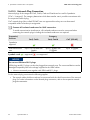
4.1 Selecting the Topology
The flexible network design is an essential benefit of Speedwire. The Speedwire devices selected and
their physical arrangement within the PV system determine which topology is the ideal selection.
The maximum line lengths allowed between the Speedwire devices may not be exceeded
(see Section 3.3.2 "Maximum Line Lengths (End-to-End-Links)", page 11). If the line lengths are
exceeded, a media converter must be used for optical fibers (see Section 4.1.3 "Tree Topology",
page 25).
The Speedwire network can be set up with the following optional topologies:
• Line topology (see Section 4.1.1, page 23)
• Star topology (see Section 4.1.2, page 24)
• Tree topology (see Section 4.1.3, page 25)
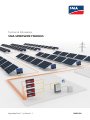
4.1.1 Line Topology
Requirement:
☐ The inverters must be equipped with Speedwire interfaces with two network plugs each.
One network port is sufficient for the end user of a line topology.
Figure 8:
Line topology with Cluster Controller (example)
Technical Information
Speedwire-TI-en-11
23
4 Basics for Planning a PV System with Speedwire
SMA Solar Technology AG
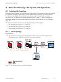
4.1.2 Star Topology
Figure 9:
24
Star topology (example)
Speedwire-TI-en-11
Technical Information
SMA Solar Technology AG
4 Basics for Planning a PV System with Speedwire
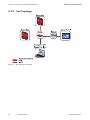
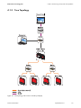
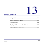
4.1.3 Tree Topology
Figure 10: Tree topology with Cluster Controller (example)
Technical Information
Speedwire-TI-en-11
25
4 Basics for Planning a PV System with Speedwire
SMA Solar Technology AG
4.2 Information on Laying the Network Cables
4.2.1 General Information
To ensure the optimal operation of a Speedwire PV system, the following normative guidelines must
be observed when laying network cables among other things:
• EN 50174-2 (2000) Information technology – Installation of communication cabling part 2: Installation planning and practices in buildings
• EN 50174-3 (2003) Information technology – Installation of communication cabling part 3: Installation planning and practices outside of buildings
Observe national standards and directives
In addition to the international standards mentioned here, there can be additional national
safety and laying directives for energy and data cables in your country.
• When laying network cables, observe the safety and laying directives for energy and
data cables applicable in your country in addition to the international standards.
4.2.2 Information on Interference Suppression
• Observe the network cable requirements (see Section 3.4.1, page 13).
• When laying network cables, create a clearance as great as possible to other cables and
observe the following minimum clearances:
– Network cable to unshielded energy cable without separating strip: at least 200 mm
– Network cable to unshielded energy cable with aluminum separating strip: at least 100 mm
– Network cable to unshielded energy cable with steel separating strip: at least 50 mm
– Network cable to shielded energy cable: 0 mm
– Network cable to network cable: 0 mm
• Keep parallel routing of network cables and other cables to a minimum.
• When cables of different categories are crossed, make a rectangular crossing.
• Always use suitable cable glands for the inverter or switch cabinet enclosure openings.
• When laying the network cables outdoors, always lay them on metallically conductive
cableways.
• Connect the joints of the cableways covering a large area and with good conductivity.
The connection must be of the same material as the cableways.
• Ground metallically conductive cableways.
26
Speedwire-TI-en-11
Technical Information
SMA Solar Technology AG
4 Basics for Planning a PV System with Speedwire
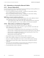
4.2.3 Mechanical Protection of Network Cables
/05*$&
Network cables can only be mechanically stressed to a certain extent
The network cables can be damaged when being twisted or bent or being mechanically stressed
when applying pressure or being pulled.
• Observe the following mechanical safety measures when laying network cables. The network
cable will be protected from cable break, short circuit of the wires and from damage to the
cable sheath and cable shield.
• When laying outside of cableways, lay the network cables in a protective plastic tube.
• When laying outside of cableways in areas with heavy mechanical stress, lay the network
cables in a metal armored conduit. In areas with light or medium mechanical stress, it is sufficient
to lay the cables in protective plastic tubes.
• When laying in a 90° bend or across a building gap (e.g. expansion joint) the protective tube
must be cut off. Do not come below the minimum allowable bending radius. It is imperative not
to bend the network cables. Refer to the manufacturer's datasheet for the allowable bending
radius.
• Lay the network cables in metallic armored conduits or on metallic cableways in areas or parts
of buildings that are accessible or in the vicinity of transport routes.
• When storing or transporting the network cables, close both cable ends with a protective cap.
Oxidation of individual wires or potential moisture and dirt collection on the network cables will
be prevented.
• Laying cables over sharp edges such as cutting edges or end edges of cable channels should
be avoided by all means.
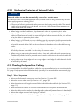
4.3 Checking the Speedwire Cabling
It is recommended to check the Speedwire cabling for correct installation prior to commissioning the
PV system. Each connection should be checked, especially if the network cables and network plugs
were self-assembled.
Step 1 - Visual Inspection
• Were qualified network components used (see Section 3.2, page 10)?
• Were the correct cables used (see Section 3.4.1, page 13)?
• Was the maximum total length observed for the individual end-to-end-links (see Section 3.3.2,
page 11)?
• Was the maximum number of interfaces not exceeded in the respective end-to-end-link?
• Were the cables not bent and was the bending radius observed (see manufacturer's data sheet)?
• Were sharp edges removed when laying the cables?
• Were the clearances to unshielded energy cables observed (see Section 4.2.2, page 26)?
Technical Information
Speedwire-TI-en-11
27
4 Basics for Planning a PV System with Speedwire
SMA Solar Technology AG
Step 2 - Simple Cabling Inspection
• Test the cable shield and all wires individually with a continuity tester for electrical connection.
An Ethernet line tester can be used instead of the continuity tester.
• Were all insulated conductor ends positioned correctly (e.g. test with wiremap LAN tester)?
• Using a continuity tester, make sure that there are no short circuits between the wires and the
cable shield. An Ethernet line tester can be used instead of the continuity tester.
• Were all cable shields properly positioned at the plugs (see Section 3.4.2.2, page 19)?
• Was the topology observed (see Section 4.1, page 23)?
Step 3 - Extensive Cabling Inspection
The extensive cabling inspection is especially recommended when there are more than two interfaces
in the end-to-end-link.
If necessary, the path attenuation must be reduced or the end-to-end link shortened to meet the
channel class D requirements.
1. Measure with an Ethernet functional or acceptance tester:
An Ethernet functional tester can be used to measure if and how fast data packages can be
transmitted over the distance measured. Cabling parameters such as cable length, attenuation,
crosstalk, etc. can also be measured.
For further information on Ethernet functional and acceptance testers, refer to the technical
documentation of the respective device.
2. Diagnosis of the cabling with the computer: Speedwire data traffic can be recorded and
analyzed when a computer with diagnostic software is connected to the Speedwire network
already in operation. The diagnostic software available on the market cannot be described
more closely in this document due to its functions and operation being different. For further
information on Ethernet diagnostic software, refer to the technical documentation of the
respective software.
Acceptance of data links
When accepting data links, it is recommended to measure each link with an acceptance tester
and to document the test results in a measurement report.
If tested and pre-assembled patch cables are used for connecting interfaces and nodes, it is
sufficient to test the fixed part of the connection (permanent link).
28
Speedwire-TI-en-11
Technical Information
SMA Solar Technology AG
5 Commissioning and Operation of a PV System with Speedwire
5 Commissioning and Operation of a PV System with
Speedwire
When using routers or network switches with router function, make sure that Speedwire uses
addresses from the Multicast area 239/8 besides directly communicating with the individual
IP nodes. The Multicast address group 239/8 (239.0.0.0 to 239.255.255.255) is defined by
RFC 2365 as a locally managed address space with local and regional expansion or throughout the
organization.
Observe router configuration
Make sure that the routers and network switches in your Speedwire network forward the
Multicast telegrams (telegrams with destination address 239.0.0.0 to 239.255.255.255)
required for the Speedwire connection to all nodes of the Speedwire network (for information
on configuration of the router or network switch, see the manufacturer's manual).
Checking the Speedwire Communication with Sunny Explorer
Requirements:
☐ The PV system may only consist of a maximum of 50 inverters.
☐ The PV system must be in operation.
☐ Automatic IP address allocation with DHCP must be activated in your computer network settings.
☐ Sunny Explorer from software version 1.06 must be installed on the computer.
☐ Inverters with Speedwire/Webconnect Piggy-Back must be in feed-in operation to be captured.
Procedure:
1. Connect the computer to the router network port or network switch in the Speedwire network.
2. Start Sunny Explorer.
3. For PV systems not yet set up in Sunny Explorer, create a new Speedwire PV system in
Sunny Explorer (see Sunny Explorer help).
4. Open the PV system already created in Sunny Explorer (see Sunny Explorer help).
5. Test whether all inverters have been detected.
Refer to troubleshooting (see Sunny Explorer help) if not all of the inverters were captured.
Technical Information
Speedwire-TI-en-11
29
5 Commissioning and Operation of a PV System with Speedwire
SMA Solar Technology AG
Checking the Speedwire Communication with a Communication Device
(e.g. Cluster Controller)
Requirements:
☐ The PV system with communication device must be in operation.
☐ The computer and the communication device must be located in the same local network.
☐ Inverters with Speedwire/Webconnect Piggy-Back must be in feed-in operation to be captured.
Procedure:
1. Connect the computer to a free network port within the local network.
2. Call up the communication device user interface via the Internet browser (see communication
device user manual).
30
Speedwire-TI-en-11
Technical Information
SMA Solar Technology AG
6 FAQ
6 FAQ
Why is it smart to use Speedwire?
Due to performance reasons it is not possible to comply with the current standards and directives for
grid integration of PV energy in all cases using the standard wired RS485 technology.
As opposed to this, Speedwire is a means to provide a continuous high-speed bus system for a
future-proof PV system monitoring that also enables you to reliably control and regulate the PV system
using the digital interface. By using Speedwire, the normative and legal requirements can be complied
with both domestically and internationally.
Is Speedwire the same as Ethernet?
No. Speedwire is an Ethernet based system with a communication protocol (SMA Data2+) optimized
for PV systems.
Are Speedwire and Webconnect the same thing?
No. The Webconnect function enables direct data transmission between the Internet portal
Sunny Portal and inverters with Webconnect interface without any additional communication device.
This data transmission takes place via a router with Internet access.
Speedwire enables data transmission within a local PV network with e.g. inverters and
Cluster Controller or Sunny Explorer.
Do I have to retrofit my router or my network switches with Speedwire?
No. Speedwire supports most standard network components (see Section 3.2 "Requirements for
Qualified Network Components", page 10) and is thereby compatible with network devices already
present.
Technical Information
Speedwire-TI-en-11
31
7 Glossary
SMA Solar Technology AG
7 Glossary
Auto IP
Standard procedure in network engineering by which the Speedwire devices receive valid
IP addresses which can be communicated with.
Auto Negotiation
Configuration protocol in Ethernet and Speedwire networks. Before the actual data transmission the
fastest possible data transfer rate is negotiated which supports each node.
Central Inverter
Inverter concept in which all PV modules are connected to each other (in series or parallel) and a
single inverter is used for feeding power into the utility grid.
DHCP
Abbreviation for "Dynamic Host Configuration Protocol". DHCP is a server service with which nodes
are automatically integrated into a local network. If no DHCP should be used by the server or router
in the network, nodes must be integrated into the local network manually. Static network settings must
be carried out for the affected nodes (an IP address suitable for the local network and subnet mask
among other things).
End-to-End-Link
Maximum line length including all connectors and interfaces between two nodes in a Speedwire
network.
Ethernet
Wire-based network connection that allows data exchange between individual nodes (hardware
such as computer, router, printer) in local networks through transfer of data packages.
Network protocols (software such as TCP/IP) control the data transmission.
Full Duplex
Data transfer method where data packages are transmitted between two nodes bidirectionally at
once. Both nodes are in send-receive-mode simultaneously.
Half Duplex
Data transfer method where data packages are bidirectionally transmitted alternately between two
nodes. Both nodes alternate between send and receive mode.
Inverter
A device for converting the direct current (DC) from the PV array into alternating current (AC),
which is necessary for connection of most normal household devices and especially for feeding
PV energy into an existing transmission line.
32
Speedwire-TI-en-11
Technical Information
SMA Solar Technology AG
7 Glossary
IP Address
A network address that is assigned to each node exactly once so that data packages can be correctly
addressed and transmitted. IP addresses can be automatically assigned when auto IP/DHCP is
activated or manually assigned to the node when auto IP/DHCP is deactivated.
Network Switch
Network device connecting the nodes to each other and allows for communication in the network
segment. The nodes are connected to each other via a network cable with the network switch.
The network switch forwards the data packages within the network segment to the addressed nodes.
PV Cell
An electronic component that generates electrical energy when irradiated with sunlight. Since the
electrical voltage of a single PV cell is very low (approximately 0.5 V), multiple PV cells are combined
with PV modules. The most common semiconductor material presently used for PV cells is silicon,
which is manufactured in different forms (monocrystalline, polycrystalline, amorphous).
PV Module
Electrical connection of several PV cells encapsulated in an enclosure to protect the sensitive cells from
mechanical stress and environmental influences.
PV System
Designation for PV systems for power generation. This includes the complete collection of components
needed for the acquisition and utilization of PV energy. In the case of grid-connected PV systems this
includes the PV array as well as the inverter and other system components.
RJ45
Standardized plug in telecommunications and network engineering, also known as Western Bell plug.
Router
Network device that connects several networks with each other and routes data between the
networks, e.g. between a home network and the Internet.
SMA Data2+
A communication product for PV systems developed and optimized by SMA Solar Technology AG.
Store and Forward Technology
The store and forward technology is a type of data transmission where information is sent via an
intermediate station (e.g a router) which stores the data and then forwards the data to the final
destination or another intermediate station at a later point in time.
Transmission Control Protocol (TCP)
Transmission protocol in computer networks which regulates the packet-switched data exchange
between the individual nodes.
Technical Information
Speedwire-TI-en-11
33
7 Glossary
SMA Solar Technology AG
Twisted-Pair Cable (TP)
Cable types in telecommunications and network engineering where the wires are twisted in pairs with
each other. By drilling the wire pairs, the EMC interference couplings in the individual wire loops have
an effect in the opposite direction and cancel each other through difference determination.
User Datagram Protocol (UDP)
Wireless network protocol belonging to the transport layer of the internet protocol family. UDP routes
the data transmitted via a network to the correct application.
Webconnect Function
A function developed by SMA Solar Technology AG which enables data transmission between the
Internet portal Sunny Portal and inverters with Speedwire/Webconnect interface without an
additional communication device. This data transmission takes place via a router with Internet access.
34
Speedwire-TI-en-11
Technical Information
SMA Solar Technology
www.SMA-Solar.com