1
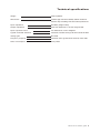
SOURCE
1
2
3
VOLUME
4
MIN
MAX
Takumi K-7 Preamplifier
Takumi K-10 Owner's guide
Thank you
We extend our hand in deep gratitude, thanking you for selecting the Takumi K-10 pre-amplifier.
This pre-amplifier is easy to install and use but there are some precautions that need to be observed
in order to attain maximum performance, safety and reliability. Please therefore read carefully thru
this owner’ s manual before installing your K-10.
If there any doubts in your mind or should you require any supplementary information, please do not
hesitate to contact your distributor or Robert Koda directly.
Cordially,
Robert Koch.
Important safety information
This unit is designed to be earthed.
Please therefore ensure that the AC power cable you select to use with the K-10 is a three wire type
that is earthed. Failure to do so may render a potentially dangerous situation.
There are no user serviceable parts inside. Please therefore do not attempt to open, adjust or modify
this pre-amplifier.
Power up and power down sequence.
Due to the fact that the K-10 does not incorporate power up / down muting circuits, a large pulse
may be emitted from the speakers if the pre-amplifier is not powered up or down in the correct
sequence. This pulse may be objectionable or even damaging to your loudspeakers and in particular
active bass systems so please:
On power up, turn the pre-amplifier on twenty seconds or more before the power amplifier(s).
On power down, turn off the power amplifiers before turning off the pre-amplifier.
Takumi K-10 Owner's guide 1
Placement requirements
Owing to the substantial 27Kg weight of the K-10, this pre-amplifier should be placed on a firm,
stable and solid surface. The use of a dedicated audio stand or plinth may provide some degree of
increased performance.
Areas of high humidity, direct sunlight, exposure to flammable gas or possible exposure to liquids are
not suitable for placing the K-10 in.
This pre-amplifier is not designed to stand directly on top of other audio components or have other
audio components placed on top of it.
Feet
Four basic feet are installed onto the under-chassis of the pre-amplifier. Their purpose is to mainly
provide “finger space” while lifting the unit. Five Sorbo Gell feet are provided for use on final
installation. Typically one would place three of the feet on the left under-side area and two on the
right. This is to compensate for the extra weight of the left hand portion of the pre-amplifier. It may
be desirable to place a thin piece of grease proof paper or similar underneath each Sorbo Gell foot if
the added sticky-ness of the foot is not desired. In addition the grease proof paper may prevent
possible staining that the foot may leave behind on the component stand.
Takumi K-10 Owner's guide 2
Connections
Inputs - Source 1
Any balanced source component may be connected to source 1. Best results will be generally obtained
when the source component offers a moderate to low output impedance as most (but not all) balanced
source components do. If your source component offers both balanced and unbalanced outputs, it may
be worthwhile to undertake a listening test to determine which one sounds best.
Inputs - Source 2 thru 4
Source 2 thru 4 are supported by RCA type single ended inputs. These three sets are all electrically
identical, offer a 50K ohm input impedance coupled with a very low input capacitance thus making them
suitable for use with a wide range of source components.
If your source components have a variable or selectable output level, we suggest that you try between
some of these settings and the fixed (or maximum) output level to see which one delivers the best
sound quality and ease of use for your system.
Outputs
Two pairs of RCA’s and one pair XLR’s are used for output connection. When the Balanced / SE switch
is set to SE, all three outputs function. The XLR’s in this case output a single ended signal with pin 2
being signal and pin 3 becomes grounded.
When the Balanced / SE switch is placed in the Balanced setting, all three outputs function. The XLR
sockets provide a full true balanced signal and the RCA’s operate normally but with a reduced gain and
output impedance.
It is possible to use any combination of output sockets simultaneously if required.
Output impedance
In SE mode the output impedance at all three pairs of outputs is 75 ohms.
In the balanced mode output impedances are 37 ohms per phase on the XLR with pin 2 being “Hot” and
pin 3 being “Cold” while being 37 ohms on the RCA outputs.
The K-10 is capable of output levels in excess of 20V RMS and is comfortable with loads as low as 1K
ohm.
A Note on the RCA sockets
Great care should be taken, especially with cables that fit too tight or use of locking systems that might
not be in sufficiently released before removing the cable from the pre-amplifier. Any un-due twisting of
the RCA sockets may cause them to loosen and possibly damage the fragile wires connected to them
on the inside of the pre-amplifier.
Takumi K-10 Owner's guide 3
AC Inlet
Unless otherwise specified, the K-10 is designed for 240V use. AC voltage is marked on the back of the
K-10, just above the AC receptacle. This pre-amplifier will function to specification on any AC voltage
between 210 and 245V.
The power requirement is 30W when the unit is on and 0W when turned off.
Please ensure that your power cord remains earthed at all times. If this pre-amplifier is not earthed via
the AC power cable the pre-amplifier may constitute a dangerous electrical shock hazard under certain
fault conditions.
Power switch
Rear mounted above the power receptacle, the power switch combines the switching function with a
circuit breaker function. Press the rocker switch so the “1” becomes indented to power the K-10 up.
Push the switch so the “0” becomes indented to turn the unit off.
Sometimes it may appear that the switch is giving a little “bounce back” at the moment of turn on. This
is normal and simply indicates there was considerable momentry current draw. It is possible that the
switch may automatically click over from the on state to the off state. Such instances could indicate a
severe fault condition. The circuit breaker may be reset by pushing it back on but if it flips over back to
off then the pre-amplifier should be disconnected from the mains supply immediately and returned to
Robert Koda for inspection.
Note: The rear power switch does not illuminate.
Ground terminal
To aid system fine tuning, a chunky ground terminal is provided.
This terminal connects internally to the K-10’s chassis and AC inlet earth.
Takumi K-10 Owner's guide 4
Front
panel description
Orange neon indicator
This indicator becomes illuminated when the power is on.
Volume control
Adjust as required. Please note that compared to other pre-amplifiers, you may need to turn the control
to a higher setting that you are accustomed to. The specific setting needed is however not relevant to
system performance and the K-10’s volume is so designed.
Input selector
Use this to select the required input 1 thru 4.
General
use
Burn in time
If your K-10 has not been used for some months, relocated or is brand new, it might require two or
three days of power on state to “bed in the components”. Such may be done by simply leaving the
pre-amplifier on for a couple of days. It is not specifically required for the K-10 to be passing thru a
music signal during this process.
Warm up time
Upon power up the K-10 will become functional after about twenty seconds or so. After a further twenty
minuets, optimal sound quality will be available.
Please note: The K-10 is not designed to be left on permanently. Please turn it off when there is no
intended use for some time.
Cleaning and maintenance
The K-10 may be dusted down with a soft cloth. A cloth dampened in a mild solution of soap and warm
water may be effective at removing grease.
If you live in a corrosive environment it may be worthwhile to keep the K-10 covered with a large cloth
when not in use. To keep the K-10 looking brand new it may also be beneficial to guard any un-used
input and output sockets with a suitable masking tape or similar.
Servicing
Servicing should only be undertaken when there is a fault condition within the pre-amplifier. Please
contact your distributor or alternatively Robert Koda for advice and we will provide prompt assistance.
There are no user serviceable parts inside this pre-amplifier.
Takumi K-10 Owner's guide 5
Technical
specifications
Weight
27Kg unpacked.
Dimensions
169mm high with feet installed, 380mm wide and
380mm deep excluding knob and socket protrusions.
Input impedance
50K Ohm (Single ended)
Output impedance
2X37 ohm balanced, 1X 75 ohm single ended.
Input equivalent noise
3.5 millionths of a volt A weighted
Typical mid-band distortion
Less than 0.0005% driving 10K ohm load at 4V RMS
Voltage gain
Plus 6 dB
Frequency response
Less than 3Hz to greater than 150 KHz, minus 3dB
Power consumption
Thirty watts.
Takumi K-10 Owner's guide 6
The meaning of "Takumi"
The meaning of the Japanese character “Takumi”
can be translated as “Maestro”.
Our brand endeavours to build a product in the
spirit of Maestro.
Robert-Koda LLC
1-9-4 Azusawa Itabashi-Ku Tokyo
174-0051 Japan