1
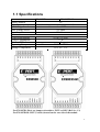
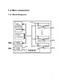
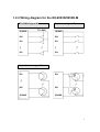
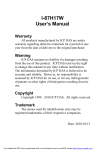
1. Introduction
EX-9053D/9053D-M provides 16 non-isolated digital input channels. All
input channels are single ended with common ground. (See Sec. 1.2.1 Block
diagram)
Specifications
Interface : RS-485, 2 wires
Speed : 1200, 2400, 4800, 9600, 19.2K, 38.4K, 57.6K,115.2K
Input channels : 16 non-isolated input channels (single ended).
Logical level 0 : +2VDC Max.
Logical level 1 : +4V ~ +30VDC
Input impedance : 820 ohms
LED: 16 digital input status LED
Power input : +10V to +30VDC
Power Consumption : 1.7W
1
1.1 Specifications
EX-9053D
Input Channels
Input Type
ON Voltage Level
OFF Voltage Level
Input Impedance
Environment
Power Requirement
Power Consumption
Modbus RTU
Operating Temperature
Storage Temperature
EX-9053D-M
16
non-isolated input channels (single ended).
+4 to 30V
+2V Max
820 Ohms
Not support
+10 to +30 VDC
1.7 W
Support
-25°C to +75°C
-30°C to +75°C
For EX-9053D: Pin-6 are jumper selectable to INIT* or DI15 (Ref. Sec. 1.3)
For EX-9053D-M: INIT*( switch) located on the rear side of the module
2
1.2 Wire connection
1.2.1 Block Diagrams
+5V
Led
Display
DI0
EEPROM
Single
Controller
DI14
Data+
Data-
RS485
Interface
+Vs
GND
Power
Supply
+5V
DI15
EX9053D
3
1.2.2 Wiring diagram for the EX-9053D/9053D-M
TTL/CMOS signal I/P
(B)GND
TTL.GND
Dry Contact signal I/P
(B)GND
DI0
DI0
DI1
DI1
DIx
DIx
Open Collector signal I/P
DIx
DIx
DI0
DI0
(B)GND
(B)GND
4
1.3 Default Settings
Default settings for the EX-9053D as follows:
. Protocol: ASCII command
. Module Address: 01
. DIO Type: 40
. Baud Rate: 9600 bps
Jumper Setting for select the pin INIT*/DI15
Select DI15
Select INIT*
Default settings for the EX-9053D-M as follows:
. Protocol: Modbus RTU
. Module Address: 01
. DIO Type: 40
. Baud Rate: 9600 bps
5
1.4 INIT* Mode Operation
Each EX9000 module has a build-in EEPROM to store
configuration information such as address, type, baudrate and other
information. Sometimes, user may forget the configuration of the
module. Therefore, the EX9000 have a special mode named "INIT*
mode" to help user to resolve the problem. The "INIT* mode" is
setting as Address=00, Baudrate=9600bps, no Checksum .
Originally, the INIT* mode is accessed by connecting the INIT*
terminal to the GND terminal. New EX9000 modules have the
INIT* switch located on the rear side of the module to allow easier
access to the INIT* mode. For these modules, INIT* mode is
accessed by sliding the INIT* switch to the Init position as shown
below.
To enable INIT* mode, please following these steps:
Step1. Power off the module
Step2. Connect the INIT* pin with the GND pin.
(or sliding the INIT* switch to the Init* ON position)
Step3. Power on
Step4. Send command $002 (cr) in 9600bps to read the
Configuration stored in the module's EEPROM.
There are commands that require the module to be in INIT* mode.
They are:
1. %AANNTTCCFF when changing the Baud Rate and checksum
settings. See Section 2.1 for details.
2. $AAPN, See Section 2.16 for details.
6
1.5 Module Status for DIO, AIO
Power On Reset or Module Watchdog Reset will let all
output goto Power On Value. And the module may accept the
host's command to change the output value.
Host Watchdog Timeout will let all output goto Safe Value.
The module's status(read by command~AA0) will be 04, and the
output command will be ignored.
1.6 Dual Watchdog Operation for DIO, AIO
Dual Watchdog=Module Watchdog + Host Watchdog
The Module Watchdog is a hardware reset circuit to monitor
the module's operating status. While working in harsh or noisy
environment, the module may be down by the external signal. The
circuit may let the module to work continues and never halt.
The Host Watchdog is a software function to monitor the
host's operating status. Its purpose is to prevent the network from
communication problem or host halt. When the timeout interval
expired, the module will turn all outputs to predefined Safe Value.
This can prevent the controlled target from unexpected situation.
The EX9000 module with Dual Watchdog may let the
control system more reliable and stable.
1.7 Reset Status
The Reset Status is set while the module power on or reset by
module watchdog and is cleared while the command read Reset
Status ($AA5) applied. This is useful for user to check the module's
working status. When the Reset Status is set means the module is
reset and the output may be changed to the PowerOn Value. When
the Reset Status is clear means the module is not rested and the
output is not changed.
7
1.8 Digital O/P
The module's output have 3 different situation:
<1>Safe Value. If the host watchdog timeout status is set,
the output is set to Safe Value. While the module receive the output
command like @AA(Date) or #AABBDD, the module will ignore
the command and return "!". And will not change the output to the
output command value. The host watchdog timeout status is set
and store into EEPROM while the host watchdog timeout
interval expired and only can be cleared by command ~AA1. If
user want to change the output it need to clear the host watchdog
timeout status firstly and send output command to change the output
into desired value.
<2>PowerOn Value. Only the module reset and the host
watchdog timeout status is clear, the module's output is set to
predefined Power On Value.
<3> Output Command Value. If the host watchdog timeout
status is clear and user issue a digital output command like @AA
(Data) or #AABBDD to module for changing the output value. The
module will response success (receive>).
1.9 Latch Digital I/P
For example, use connect the key switch to Digital input channel of
a digital input/output module and want to read the key stoke. The
Key input is a pulse digital input and user will lost the strike. While
reading by command $AA6 in A and B position, the response is that
no key stroke and it will lose the key stroke information. Respectely,
the read latch low digital input command $AAL0 will solve this
problem. When issue $AAL0 command in A and B position, the
response denote that there is a low pulse between A and B position
for a key stroke.
8
1.10 Configuration Tables
Baud Rate Setting (CC)
Code
Baud rate
03
04
05
06
07
08
09
0A
1200
2400
4800
9600
19200
38400
57600
115200
Data Format Setting (FF)
7
6
5
4
*1
*2
0
0
3
0
2
0
1
1
0
1
*1: Counter Update Direction: 0 =Falling Edge,
1=Rising Edge.
*2: Checksum Bit : 0=Disable, 1=Enable.
Read Digital Input/Output Data Format table
Data of $AA6,$AA4,$AALS:(First Data)(Second Data)00
Data of @AA:(First Data)(Second Data)
Note: Both the First Data and the Second Data are in two
hexadecimal digitals format.
Module
The First data
EX9053D/53D-M DI8~DI15
00~FF
The Second data
DI0~DI7
00~FF
9
2.0 Command Sets
2.1 %AANNTTCCFF
Description: Set Module Configuration.
Syntax: %AANNTTCCFF[CHK](cr)
%
AA
a delimiter character
address of setting/response module(00 to FF)
NN
TT
CC
FF
new address for setting/response module(00 to FF)
type 40 for DIO module
new baudrate for setting module.
new data format for setting module.
If the configuration with new baudrate or new checksum
setting, before using this command, it is needed to short the
INIT* to ground (or sliding the INIT* switch to the Init ON
position of rear side). The new setting is saved in the
EEPROM and will be effective after the next power-on reset.
Response: Valid Command:
Invalid Command:
!AA
?AA
Example:
Command: %0102240600
Receive: !02
Set module address 01 to 02, return Success.
10
2.2 #**
Description: Synchronized Sampling
Syntax: #**[CHK](cr)
#
delimiter character
**
synchronized sampling command
Response: No response
Example:
Command: #**
No response
Send synchronized sampling command to all modules.
Command: $014
Receive: !10F0000
Read synchronized data from address 01, return S=1, first read
and data is 0F0000
Command: $014
Receive: !00F0000
Read synchronized data from address 01, return S=0, have readed
and data is 0F0000
11
2.3 #AAN
Description: Read Digital Input Counter from channel N
Syntax : #AAN[CHK](cr)
#
delimiter character
AA
address of reading/response module (00 to FF)
N
channel to read
Response: Valid Command:
Invalid Command:
>(Data)
?AA
(Data) digital input counter value in decimal, from 00000 to
99999
Example:
Command: #032
Receive: !0300103
Read address 03 digital input counter value of channel 2, return
value 103.
Command: #025
Receive: ?02
Read address 02 digital input counter value of channel 5, return
the channel is not available.
12
2.4 $AA2
Description: Read configuration.
Syntax: $AA2[CHK](cr)
$
delimiter character
AA
address of reading/response module (00 to FF)
2
command for read configuration
Response: Valid Command:
Invalid Command:
TT
CC
FF
!AATTCCFF
?AA
type code of module, it must be 40
baudrate code of module
data format of module
Example:
Command: $012
Receive: !01400600
Read the configuration of module 01, return DIO mode, baudrate
9600, no checksum.
Note: check configuration Tables
13
2.5 $AA4
Description: Reads the synchronized data
Syntax: $AA4[CHK](cr)
$
delimiter character
AA
address of reading/response module (00 to FF)
4
command to read the synchronized data
Response: Valid Command:
Invalid Command:
!S(Data)
?AA
status of synchronized data, 1=first read, 0=been readed
S
(Data) synchronized DIO value. See Section 1.10 for data
format.
Example:
Command: #**
no response
Send synchronized sampling to all modules.
Command: $014
Receive: !100F00
Read address 01 synchronized data, return S=1, first read, and
synchronized data 0F00
14
2.6 $AA5
Description: Read Reset Status
Syntax: $AA5[CHK](cr)
$
delimiter character
AA
address of reading/response module (00 to FF)
5
command for read reset status
Response: Valid Command:
Invalid Command:
S
!AAS
?AA
reset status, 1=the module is been reset, 0=the module is
not been rested
Example:
Command: $ 015
Receive: !011
Read address 01 reset status, return module is been reset
Command: $ 015
Receive: !010
Read address 01 reset status, return no reset occurred.
15
2.7 $AA6
Description: Read Digital I/O Status
Syntax: $AA6[CHK](cr)
$
delimiter character
AA
address of reading/response module (00 to FF)
6
command for read channel status
Response: Valid Command:
Invalid Command:
(Data)
!(Data)
?AA
Digital input/output value.
Example:
Command: $016
Receive: !000F00
Assume module is EX9053, read address 01 DIO status, return
000F, digital input channel 0~3 are on.
16
2.8 $AAF
Description: Read Firmware Version
Syntax: $AAF[CHK](cr)
$
delimiter character
AA
address of reading/response module (00 to FF)
F
command for read firmware version
Response: Valid Command:
Invalid Command:
!AA(Data)
?AA
(Data) Firmware version of module
Example:
Command: $01F
Receive: !01D04.03
Read address 01 firmware version, return version D04.03
17
2.9 $AAM
Description: Read Module Name
Syntax: $AAM[CHK](cr)
$
delimiter character
AA
address of reading/response module (00 to FF)
M
address of reading/response module(00 to FF)
Response: Valid Command:
Invalid Command:
!AA(Data)
?AA
(Data) Name of module
Example:
Command: $01M
Receive: !019053
Read address 01 module name, return name 9053
18
2.10 $AAC
Description: Clear Latched Digital Input
Syntax: $AAC[CHK](cr)
$
delimiter character
AA
address of reading/response module (00 to FF)
C
command for clear latched digital input
Response: Valid Command:
Invalid Command:
!AA
?AA
Example:
Command: $01L0
Receive: !FFFF00
Read address 01 latch-low data, return FFFF.
Command: $01C
Receive: !01
Clear address 01 Latched data, return success.
Command: $01L0
Receive: !000000
Read address 01 latch-low data, return 0000.
19
2.11 $AACN
Description: Clear Digital Input Counter
Syntax: $AACN[CHK](cr)
$
delimiter character
AA
address of reading/response module (00 to FF)
C
command for clear latched digital input
N
digital counter channel N to clear
Response: Valid Command:
Invalid Command:
!AA
?AA
Example:
Command: #010
Receive: !0100123
Read address 01 input channel 0 counter value, return 123.
Command: $01C0
Receive: !01
Clear address 01 input channel 0 counter value, return success.
Command: #010
Receive: !0100000
Read address 01 input channel 0 counter value, return 0.
20
2.12 $AALS
Description: Read Latched Digital Input
Syntax: $AALS[CHK](cr)
$
delimiter character
AA
address of reading/response module (00 to FF)
L
command for read latched digital input
S
1=select latch high status, 0=select latch low status
Response: Valid Command:
Invalid Command:
!(Data)
?AA
(Data) readed status 1=the input channel is latched, 0=the
input channel is not latched.
Example:
Command: $01L1
Receive: !012300
Read address 01 latch-high data, return 0123.
Command: $01C
Receive: !01
Clear address 01 Latched data, return success.
Command: $01L1
Receive: !000000
Read address 01 latch-high data, return 0000.
21
2.13 @AA
Description: Read Digital I/O Status
Syntax: @AA[CHK](cr)
@
delimiter character
AA
address of reading/response module (00 to FF)
Response: Valid Command:
Invalid Command:
(Data)
>(Data)
?AA
Digital input/output value.
Example:
Command: @01
Receive: >000F
Assume module is EX9053, read address 01 DIO status, return
000F, digital input channel 0~3 are on
22
2.14 ~AAO(Data)
Description: Set Module Name
Syntax: ~AAO(Data)[CHK](cr)
~
delimiter character
AA
address of reading/response module (00 to FF)
O
command for set module name
(Data) new name for module, max 6 characters
Response: Valid Command:
Invalid Command:
!AA
?AA
Example:
Command: ~01O9053
Receive: !01
Set address 01 module name 9053, return success.
Command: $01M
Receive: !019053
Read address 01 module name, return name 9053.
23
2.15 $AAP (only for EX9053D-M)
Description: Read protocol information of Module
Syntax: $AAP[CHK](cr)
$
delimiter character
AA
address of reading/response module (00 to FF)
P
command for read protocol information of module
Response: Valid Command:
Invalid Command:
S
!AAS
?AA
The protocol supported by the module
10: the protocol set in EEPROM is Normal mode
11: the protocol set in EEPROM is ModbusRTU mode
Example:
Command: $01P
Receive: !0110
Reads the communication protocol of module 01 and returns a
response of 10 meaning the protocol that will be used at the next
power on reset is normal mode.
Command: $01P1
Receive: !01
Sets the communication protocol of module 01 to Modbus RTU
and returns a valid response. And the next power on reset is in
ModbusRTU mode.
24
2.16 $AAPN (only for EX9053D-M)
Description: Set the protocol information of Module
Syntax: $AAPN[CHK](cr)
$
delimiter character
AA
address of reading/response module (00 to FF)
P
command for set protocol information of module
N
The protocol supported by the module
0: the protocol set in EEPROM is Normal mode
1: the protocol set in EEPROM is ModbusRTU mode
Before using this command, it is needed to short the
INIT* to ground (or sliding the INIT* switch to the Init
ON position of rear side). The new protocol is saved in
the EEPROM and will be effective after the next
power-on reset.
Response: Valid Command:
Invalid Command:
!AA
?AA
Example:
Command: $01P1
Receive: !01
Sets the communication protocol of module 01 to Modbus RTU
and returns a valid response. And the next power on reset is in
ModbusRTU mode.
25
2.17 ~**
Description: Host OK
Host send this command to all modules for send the
information “Host OK”
Syntax: ~**[CHK](cr)
~
delimiter character
**
command for all modules
Response: No response
Example:
Command: ~**
No response
26
2.18 ~AA0
Description: Read Module Status
Syntax: ~AA0[CHK](cr)
~
delimiter character
AA
address of reading/response module (00 to FF)
0
command for read module status
Response: Valid Command:
Invalid Command:
SS
!AASS
?AA
module status, 00= host watchdog is disabled & host
watchdog timeout status is clear; 80= host watchdog is
enabled & host watchdog timeout status is clear; 84=
host watchdog is enabled & host watchdog timeout
status is set . The status will store into EEPROM and
only may reset by the command~AA1.
SS
00
80
84
Host watchdog
Disable
Enable
Enable
Host watchdog timeout status
Clear
Clear
Set
27
2.19 ~AA1
Description: Reset Module Status
Syntax: ~AA1[CHK](cr)
~
delimiter character
AA
address of reading/response module (00 to FF)
1
command for reset module status
Response: Valid Command:
Invalid Command:
!AA
?AA
28
2.20 ~AA2
Description: Read the Host Watchdog Timeout Value
Syntax: ~AA2[CHK](cr)
~
delimiter character
AA
address of reading/response module (00 to FF)
2
command for read host watchdog timeout value
Response: Valid Command:
Invalid Command:
E
VV
!AAEVV
?AA
host watchdog enable status, 1=Enable, 0=Disable
timeout value in HEX format, each count is 0.1 second
01=0.1 second and FF=25.5 seconds
29
2.21 ~AA3EVV
Description: Set host Watchdog Timeout Value
Syntax: ~AA3EVV[CHK](cr)
~
delimiter character
AA
address of reading/response module (00 to FF)
3
command for set host watchdog timeout value
E
1=Enabled / 0=Disable host watchdog
VV
timeout value, from 01 to FF, each for 0.1 second
Response: Valid Command:
Invalid Command:
!AA
?AA
Example:
Command: ~010
Receive: !0100
Read address 01 modules status, return host watchdog timeout
status is clear.
Command: ~013164
Receive: !01
Set address 01 host watchdog timeout value 10.0 seconds and
enable host watchdog, return success.
Command: ~012
Receive: !01164
Read address 01 host watchdog timeout value, return that host
watchdog is enabled, and time interval is 10.0 seconds.
Command: ~**
No response
30
Reset the host watchdog timer. Wait for about 10 seconds and
don't send command~**, the LED of module will go to flash.
The flash LED indicates the host watchdog timeout status is set.
Command: ~010
Receive: !0104
Read address 01 module status, return host watchdog timeout
status is set.
Command: ~012
Receive: !01064
Read address 01 host watchdog timeout value, return that host
watchdog is disabled, and time interval is 10.0 seconds.
Command: ~011
Receive: !01
Reset address 01 host watchdog timeout status, return success
And the LED of this module stop flash.
Command: ~010
Receive: !0100
Read address 01 module status, return host watchdog timeout
status is clear.
31
EX9053-M Quick Start
1. The default setting is MODBUS mode after Power On.
Init* to GND
2. Sliding the INIT* switch to the Init*(ON) position
ON
of rear side then Power On will enter INIT* mode
(use ASCII command).
1
Normal
3. On ASCII command mode, user can set other setting like Address,
Baudrate, …by use ASCII command or Utility of EX9000 (Please check
the User Manual of EX9000).
Init* to GND
4. After change the setting finished, Sliding the INIT* ON
switch to the Normal(1) position of rear side, the
new setting will be effective after the next power-on
reset.
1
Normal
32
01(0x01) Read Digital Input Value
Request
00
Address
01
Function code
02~03 Starting channel
1 Byte 1-247
1 Byte 0x01
2 Bytes 0x0020~0x002F for DI readback value
0x0040~0x004F for DI Latch high value
0x0060~0x006F for DI Latch low value
04~05 channel numbers 2 Bytes 0x0001~0x0010
Response
00
Address
01
Function code
02
Byte count
03
Input/Output
channel readback
value
Error Response
00
Address
01
Function code
02
Exception code
1 Byte
1 Byte
1 Byte
1 Byte
1-247
0x01
1
0x00~0x0F
A bit corresponds to a channel. When the
bit is 1 it denotes that the value of the
channel that was set is ON. if the bit is 0 it
denotes that the value of the channel that
was set is OFF.
1 Byte
1 Byte
1 Byte
1-247
0x81
Refer to the Modbus standard for more
details.
33
02(0x02) Read Digital Input Value
Request
00
Address
01
Function code
02~03 Starting channel
04~05 channel numbers
Response
00
Address
01
Function code
02
Byte count
03
Input channel
readback value
Error Response
00
Address
01
Function code
02
Exception code
1 Byte
1 Byte
2 Bytes
2 Bytes
1-247
0x02
0x0000~0x000F
0x0001~0x0010
1 Byte
1 Byte
1 Byte
1 Byte
1-247
0x02
1
0x00~0x0F
A bit corresponds to a channel. When the
bit is 1 it denotes that the value of the
channel that was Input response. if the bit
is 0 it denotes that the value of the channel
that was no Input response .
1 Byte
1 Byte
1 Byte
1-247
0x82
Refer to the Modbus standard for more
details.
34
03(0x03) Read Digital Input Count Value
Request
00
Address
01
Function code
02~03 Starting channel
04~05 channel numbers
1 Byte
1 Byte
2 Bytes
2 Bytes
1-247
0x03
0x0000~0x000F
0x0001~0x0010
Response
00
Address
1 Byte 1-247
01
Function code
1 Byte 0x03
02
Byte count
1 Byte 1
03~ Input channel
N* x 2 Each channel can record a maximum
count value
Byte
count value up to 65535(0xFFFF).
N*=Number of input channels
Error Response
00
Address
01
Function code
02
Exception code
1 Byte
1 Byte
1 Byte
1-247
0x83
Refer to the Modbus standard for more
details.
35
04(0x04) Read Digital Input Count Value
Request
00
Address
01
Function code
02~03 Starting channel
04~05 channel numbers
1 Byte
1 Byte
2 Bytes
2 Bytes
1-247
0x04
0x0000~0x000F
0x0001~0x0010
Response
00
Address
1 Byte 1-247
01
Function code
1 Byte 0x04
02
Byte count
1 Byte 1
03~ Input channel
N* x 2 Each channel can record a maximum
count value
Byte
count value up to 65535(0xFFFF).
N*=Number of input channels
Error Response
00
Address
01
Function code
02
Exception code
1 Byte
1 Byte
1 Byte
1-247
0x84
Refer to the Modbus standard for more
details.
36
05(0x05) Clear DI count Value (Single channel)
Request
00
Address
01
Function code
02~03 channel number
04~05 Clear DI count
value
Response
00
Address
01
Function code
02~03 Output channel
numbers
04~05 Output value
Error Response
00
Address
01
Function code
02
Exception code
1 Byte 1-247
1 Byte 0x05
2 Bytes 0x0107 to clear the latch value
0x0200~0x020F to clear the DI counter
value
2 Bytes A value of 0xFF00 sets the output to ON.
A value of 0x0000 set it to OFF. All other
values are illegal and won’t affect the coil.
1 Byte 1-247
1 Byte 0x05
2 Bytes The value is the same as byte 02 and
03 of the Request
2 Bytes The value is the same as byte 04 and
05 of the Request
1 Byte
1 Byte
1 Byte
1-247
0x85
Refer to the Modbus standard for more
details.
37
15(0x0F) Clear DI count Value (Multi channel)
Request
00
Address
01
Function code
02~03 Starting channel
1 Byte 1-247
1 Byte 0x0F
2 Bytes 0x0200~0x020F to clear the DI counter
value
04~05 channel numbers 2 Bytes 0x0001~0x0010
06
Byte count
1 Byte 2
07
Clear DI count
1 Byte 0x0000~0xFFFF
A bit corresponds to a channel. When the bit is 1
value
it denotes that the value of the channel that was
set is ON. if the bit is 0 it denotes that the value
of the channel that was set is OFF.
Response
00
Address
01
Function code
02~03 Starting channel
04~05 Output channel
numbers
1 Byte 1-247
1 Byte 0x0F
2 Bytes The value is the same as byte 02 and
03 of the Request
2 Bytes The value is the same as byte 04 and
05 of the Request
Error Response
00
Address
01
Function code
02
Exception code
1 Byte
1 Byte
1 Byte
1-247
0x8F
Refer to the Modbus standard for more
details.
38
01(0x01) Read WDT timeout status
Request
00
Address
01
Function code
02~03 Starting channel
04~05 Output channel
numbers
1 Byte
1 Byte
2 Bytes
2 Bytes
1-247
0x01
0x010D
0x0001
Response
00
Address
01
Function code
02
Byte count
03
Output channel
readback value
1 Byte
1 Byte
1 Byte
1 Byte
1-247
0x01
1
0x00 The WDT timeout status is clear
0x01 The WDT timeout status is enable
Error Response
00
Address
01
Function code
02
Exception code
1 Byte 1-247
1 Byte 0x81
1 Byte Refer to the Modbus standard for more
details.
39
03(0x03) Read WDT timeout Value
Request
00
Address
01
Function code
02~03 Starting channel
04~05 Input channel
numbers
1 Byte
1 Byte
2 Bytes
2 Bytes
1-247
0x03
0x01E8
0x0001
Response
00
Address
01
Function code
02
Byte count
03~ Input channel count
value
1 Byte
1 Byte
1 Byte
1 Byte
1-247
0x03
2
0x0000~0x00FF WDT timeout
value, 0~255, in 0.1 second
Error Response
00
Address
01
Function code
02
Exception code
1 Byte 1-247
1 Byte 0x83
1 Byte Refer to the Modbus standard for
more details.
40
03(0x03) Send Host OK
Request
00
Address
01
Function code
02~03 Starting channel
04~05 Input channel numbers
1 Byte
1 Byte
2 Bytes
2 Bytes
1-247
0x03
0x3038
0x0000
No Response
04(0x04) Send Host OK
Request
00
Address
01
Function code
02~03 Starting channel
04~05 Input channel numbers
1 Byte
1 Byte
2 Bytes
2 Bytes
1-247
0x04
0x3038
0x0000
No Response
41
05(0x05) Set WDT timeout /Clear WDT timeout status
Request
00
Address
01
Function code
02~03 Output channel
number
04~05 Output value
Response
00
Address
01
Function code
02~03 Output channel
numbers
04~05 Output value
Error Response
00
Address
01
Function code
02
Exception code
1 Byte 1-247
1 Byte 0x05
2 Bytes 0x0104 Set WDT timeout
enable/disable
0x010D Clear WDT timeout status
2 Bytes 0xFF00 for WDT timeout enable
0x0000 for WDT timeout disable
0xFF00 for Clear WDT timeout
status
1 Byte 1-247
1 Byte 0x05
2 Bytes The value is the same as byte 02 and
03 of the Request
2 Bytes The value is the same as byte 04 and
05 of the Request
1 Byte 1-247
1 Byte 0x85
1 Byte Refer to the Modbus standard for
more details.
42
06(0x06) Set WDT timeout Value
Request
00
Address
01
Function code
02~03 Starting channel
04~05 Input channel
numbers
Response
00
Address
01
Function code
02~03 Output channel
numbers
04~05 Output value
Error Response
00
Address
01
Function code
02
Exception code
1 Byte
1 Byte
2 Bytes
2 Bytes
1-247
0x06
0x01E8
0x0000~0x00FF WDT timeout
value, 0~255, in 0.1 second
1 Byte 1-247
1 Byte 0x06
2 Bytes The value is the same as byte 02 and
03 of the Request
2 Bytes The value is the same as byte 04 and
05 of the Request
1 Byte 1-247
1 Byte 0x86
1 Byte Refer to the Modbus standard for
more details.
43
Modbus Mapping Table:
EX9053M (DI*16)
ADDR
00033~00048
Item
Digital Input channel for DI0~15
Attribute
R
00065~00080
00097~00112
00264
DI Latch high value for DI0~15
DI Latch low value for DI0~15
Clear the Latch value
R
R
W
30001~30016
00513~00528
Digital input counter for DI0~15
Clear the DI counter value for DI0~15
R
W
44