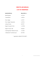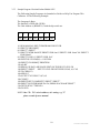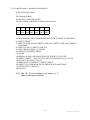
1
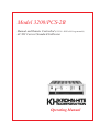
Model 3200/PCS-2B
Manual and Remote Controlled (PCS-2B - IEEE-488 Programmable)
AC/DC Current Standard/Calibrator
Operating Manual
This page intentionally left blank.
3200/PCS2-B
OPERATORS
MANUAL
Serial No.______________
win-man\3200-PCS2B
MODEL 3200/PCS2-B
OPERATORS
MANUAL
Copyright © 1999
Krohn-Hite Corporation
15 Jonathan Drive Unit 4
Brockton, Massachusetts 02301
E-mail: [email protected]
www.krohn-hite.com
All rights reserved. No part of this publication may be reproduced, stored in a retrieval system or transmitted in any
form by any means, electronic, mechanical photocopying, recording, or otherwise, without the prior written
permission of Krohn-Hite Corporation .
Printed in U.S.A.
Version 4.20
Revised June 2000
Information furnished in this manual is believed to be accurate and reliable. However, no responsibility is assumed
by Krohn-Hite Corporation for its use; nor for any infringements of patents or other rights of third parties which
may result from its use.
win-man\3200-PCS2B
This page intentionally left blank.
TABLE OF CONTENTS
SECTION
TITLE
i
ii
iii
iv
List of Drawings
Limited Warranty
Factory Service Request & Authorization
Packing Suggestions
I
DESCRIPTION AND SPECIFICATIONS
1.1.0
1.2.0
1.3.0
1.4.0
1.5.0
1.6.0
General Description
Application
General Specifications
Input Specifications
Output Specifications
General Computer Interface Specifications *
II
INSTALLATION
2.1.0
2.2.0
Mounting
Mating Connectors & cables
III
OPERATION OF THE INSTRUMENT
3.1.0
3.2.0
3.3.0
3.4.0
3.5.0
General
Interconnections
Special Operating Considerations
Programming via the IEEE 488 (GPIB) Bus *
Sample Programs *
IV
THEORY OF OPERATION
4.1.0
4.2.0
4.3.0
4.4.0
4.5.0
Introduction
Power Supply
Control Board
Digital Circuitry
Analog Circuitry
V
CALIBRATION
5.1.0
5.2.0
5.3.0
5.4.0
P.A. Idle Current Adjustment
Amplifier Offset Adjustment
Load Regulation Calibration
Output Current Calibration
VI
6.1.0
PARTS LIST
Replacement Parts for 3200/PCS-2B
* Applicable to Model PCS-2B only
NOTE:
Errata and addendum (if any) will appear in the back of this manual.
win-man\3200-PCS2B
3200/PCS-2B MANUAL
LIST OF DRAWINGS
DESCRIPTION
DRAWING #
Block Diagram
A-4714A
Control Board
A-4076A
Power Supply
A-4571C
Power Supply Components
A-4574A
Analog Circuitry
B-4572C
Digital Circuitry PCS-2B
C-4573B*
Digital Circuitry 3200
B-4603B
Load Regulation Calibration Layout
A-4125B
Calibration & Test Point Layout
B-4712D
* Applicable to Model PCS-2B ONLY.
i
win-man\3200-PCS2B
LIMITED WARRANTY
The Krohn-Hite Corporation warrants to the original purchaser each instrument
manufactured by them to be free from defects in material and workmanship. This warranty is
limited to servicing, repairing and/or replacing any instrument or part thereof returned to the
Krohn-Hite factory for that purpose in accordance with the instructions set forth below; and
furthermore to repair or replace all materials, except tubes, fuses, transistors and other
semiconductor devices which shall within ONE YEAR of shipment to the original purchaser be
returned to the Krohn-Hite factory and upon examination be deemed defective.
Krohn-Hite instruments may not be returned to the factory under the terms of this
warranty without the prior authorization of the Krohn-Hite Service Department. All instruments
returned to Krohn-Hite for service hereunder should be carefully packed and shipped. All
transportation charges shall be paid by the purchaser.
Krohn-Hite reserves the right to discontinue instruments without notice and to make
changes to any instrument at any time without incurring any obligation to so modify instruments
previously sold.
This warranty is expressly in lieu of all other obligations or liabilities on the part of
Krohn-Hite. No other person or persons is authorized to assume in the behalf of Krohn-Hite any
liability in the connection with the sale of its instruments.
CAUTION: The instrument you have purchased is a precision instrument
manufactured under exacting standards. Any attempts to repair, modify or
otherwise tamper with the instrument by anyone other than an Krohn-Hite
employee or authorized representative may result in this warranty becoming void.
ii
win-man\3200-PCS2B
FACTORY SERVICE REQUEST
AND
AUTHORIZATION
WARRANTY SERVICE
Instruments may be returned only on prior authorization. Please
obtain a RETURN AUTHORIZATION NUMBER either directly from the
factory or from an authorized Krohn-Hite Representative. (See General
Information below.)
CHARGEABLE REPAIRS
If requested, an estimate of charges will be submitted prior to
repairs. We suggest that you request a RETURN AUTHORIZATION NUMBER
to facilitate handling.
GENERAL INFORMATION
A) Please provide the following information in order to expedite the repair:
1) Indicate Model
2) Serial Number
3) Complete description of the trouble:
Symptoms, measurements taken, equipment used, lash-up
procedures, attempted repairs, suspected location of
failure and any other pertinent information.
B) Freight Charges must be PREPAID.
C) The RETURN AUTHORIZATION NUMBER should be noted on your documentation.
D) See Packing Suggestions - next page.
iii
win-man\3200-PCS2B
PACKING SUGGESTION
Although your Krohn-Hite instrument is built for laboratory, production environment and some
field environment, it is NOT ruggedized.
Therefore . . . . . . .
1.
Be sure the carton is STRONG enough to carry the weight of the instrument, e.g. use
double wall corrugation.
2.
Be sure the carton is LARGE enough to allow for sufficient packing material, e.g., at least
2 inches all around the instrument. The packing material should be able to be compressed
and then return to its approximate original volume.
3.
For better handling, the shipment should always be by AIR FREIGHT (except for short
distances). You might use either UPS "blue label" or common air freight carrier, second
day air.
Please do not bounce it across the country in a truck. It may not hurt it, but it certainly is
not going to do a laboratory instrument much good.
4.
QUESTIONS? Just contact us. We will be pleased to help you.
iv
win-man\3200-PCS2B
SECTION I
1.0.0
DESCRIPTION AND SPECIFICATIONS
1.1.0 General Description
1.1.1
This high current calibrator is an accurate voltage to current amplifier or transconductance
amplifier. The application of a precise voltage to the input terminals produces a proportional
current into any load within the compliance range of the instrument. The input voltage can be
AC or DC up to 1 kHz.
1.1.2
The unit is laboratory calibrated with instruments and load resistors traceable to
US NATIONAL INSTITUTE OF STANDARDS & TECHNOLOGY.
1.1.3
The circuitry is solid state. Derated components are used throughout to minimize temperature
effects. The input is protected against over-voltage and has a high output impedance.
1.1.4 The models 3200 and PCS-2B are equipped for rack mounting in a standard 19 inch rack. It is
completely enclosed in dust covers and therefore suitable for bench top use. Tilt bale is available
on request.
1.1.5
The instrument has been designed to be easily transported from one location to another and will
be within operational specifications within one minute after power is applied.
1.1.6
The unit may be permanently mounted in a standard 19" rack and requires only 5" of space.
1.2.0
Applications
Direct calibration of watt meters (with applicable voltage standard), meter shunts, ac & dc
current meters, current to voltage transducers, current to pneumatic transducers, dvms, dmms,
and relay coil current testing.
1
win-man\3200-PCS2B
1.3.0
General Specifications
1.3.1
Power Requirement (selectable):
115 or 220 Vac ±10%; 50/60 Hz; 150 W
1.3.2
Temperature:
Calibration
Nominal Operating
Safe Operation
Storage
Temperature Coefficient
23 º C ± 1 º C
20 º C to 30 º C
0 º C to 55 º C
-20 º C to 60 º C
50 ppm/º C - 10A & 1A Ranges;
10 ppm/º C - 100, 10 & 1 mA Ranges.
*Temperature coefficient is an adder to uncertainty specification that does not apply unless
operating more than ± 5 º C from the calibration temperature
1.3.3
Weight:
Shipping Weight:
23 Lbs.; 10.44 Kg
(USA) 25 Lbs.; 11.35 Kg
1.3.4
Dimensions:
Rack Mountable:
5.22H x 17W x 15D inches (12.25 x 43.18 x 38.1 cm)
5.22H x 19W x 16D Inches (12.25 X 48.26 X 40.64 cm)
1.3.5
Protection:
A front panel lamp illuminates to indicate when the compliance voltage has been exceeded or
when a malfunction has occurred.
1.3.6
Calibration Cycle:
One Year
1.3.7
Certification:
A Certificate of Compliance traceable to the U.S. National Institute of Standards
and Technology is supplied.
1.4.0
Input Specifications
1.4.1
Input Voltages:
0 to ± 11 Vdc or 0 to 11 Vac (rms)
1.4.2
Input Impedance:
10 kOhms (all ranges)
1.4.3
AC Band Width:
40 Hz to 1 kHz
2
win-man\3200-PCS2B
1.5.0
Output Specifications.
1.5.1
Ranges:
10 A, 1A, 100 mA, 10 mA, 1 mA
1.5.2
Resolution:
10 µA, 1 µA, 100 nA, 10 nA, 1 nA
(Limited by the resolution of the voltage calibrator)
1.5.3
Accuracy:
AC: ±(0.05% of setting +0.01% of range +20 µA)
DC: ±(0.01% of setting +0.01% of range +10 µA)
1.5.4 Compliance Voltage:
1 mA to 1 A Ranges: 5 Vdc or peak ac
10 Amp Range:
1.5 Vdc or peak ac
1.5.5
Load Regulation: (*non-additive)
1 mA, 10 mA, 100 mA ranges: ± 0.02%
1 Amp, 10 Amp ranges:
± 0.02%
1.5.6
Line Regulation: (*non-additive)
± 0.0005% for ± 10% line change
1.5.7
Stability:
DC mode - ± 0.001% of range
AC mode - ± 0.005% of range
1.5.8
Isolation:
Floating Output. Limited only by the isolation of the driving voltage source.
1.5.9
Distortion:50 Hz to 1 kHz.
1 mA to 1A Ranges: < 0.1%
10 Ampere Ranges: < 0.5%
(Added to the distortion of the AC voltage calibrator)
1.5.10 Ripple & Noise, rms: (non-additive)in band-pass 0.1 Hz to 100 kHz
Range
1 mA
10 mA
100 mA
1A
10A
Ripple & Noise
1.5 µA
3.0 µA
40 µA
80 µA
375 µA
1.6.0
IEEE 488 Specifications. (PCS-2B ONLY)
1.6.1
The Model PCS-2B may be programmed over the IEEE488 Interface Bus. The interface
functions contained in this unit are SH0 AH1 T0 L2 SR0 RL0 PP0 DC0 DT0 C0 E1.
3
win-man\3200-PCS2B
SECTION II
2.0.0
INSTALLATION
2.1.0
Mounting
2.1.1
The 3200/PCS-2B is designed for mounting in a standard 19" rack. It is recommended that
nylon washers be placed under the rack mounting screws to prevent scratching the mounting
ears.
2.1.2
A two position slide switch is mounted on the rear panel which is used to set the line voltage
requirements to 115 Vac or 230 Vac. Make sure this switch is in the proper position for your
line power prior to turning the instrument on for the first time.
2.2.0 Mating Connectors & cables
2.2.1 The instrument is supplied with a mating AC power cord. Part number CAB008.
2.2.2 IEEE 488 Connector (PCS-2B only)
2.2.3
A one or two meter IEEE STD. 488 cable may be obtained from Krohn-Hite Corp.
Part Number CAB011 for one meter & CAB010 for two meters
4
win-man\3200-PCS2B
SECTION III
3.0.0
OPERATION OF THE INSTRUMENT
3.1.0
General
3.1.1 The model 3200/PCS-2B is a voltage to current amplifier which requires only a driving source
to generate output currents to 10 amperes.
3.1.2 Operation is simple and straight forward with a few reasonable precautions to prevent damage
to equipment under test.
3.2.0
Interconnections
3.2.1 The 3200/PCS-2B should be plugged into the AC line with the power switch OFF.
3.2.2 The shorting bar supplied with the unit should be on the output terminals.
NOTE: Open Circuit Compliance Voltage Is 7.5 Volts.
3.2.3
The load may be connected to the output terminals. The connections should be made to the
inside portion of the five-way binding post. This serves two purposes, it permits removal of
the shorting bar when desired, or its reinsertion; also, a more secure, and electrically low
ohmic connection may be made, reducing the IR drop at the binding post. This is critical at
the high current levels where unnecessary IR drops reduce the available compliance voltage at
the load.
3.2.4 Select the desired range with the five-position range switch.
3.2.5 Connect suitable AC or DC voltage source to the input terminals. Select the desired input
voltage to deliver the required output current. The output current and input voltage required
may be derived as follows:
IOUT
VINPUT
VINPUT × RANGE
10
10 × IOUT
RANGE
(1)
(2)
NOTE: the Maximum Input Voltage Is 10 Vdc or rms ac.
5
win-man\3200-PCS2B
3.2.6
Turn on Model 3200/PCS-2B. When the overload light extinguishes, the shorting plug on the
output terminals may be removed. If the overload light comes on again, check load and
output connections. The load may be wrong for the current being called for:
RL,MAX
E compliance
IOUT
(3)
3.3.0 Special Operating Considerations
3.3.1
Reasonable care should be exercised in the selection of wire size used to connect high current
loads to the 3200/PCS-2B. A choice of size, with a high IR drop, or a poor connection at the
3200/PCS-2B or the load will limit the compliance voltage available at the load.
3.3.2
Accurate measurements of the current through the load should be made at the load, not at the
3200/PCS-2B terminals, i.e., as in determining resistance values of shunts, etc.
3.3.3
The model 3200/PCS-2B is factory tested and calibrated with 1kΩ , 100Ω, 10Ω, 1Ω, and
0.1Ω on the 1 mA, 10 mA, 100 mA, 1A, and 10A ranges, respectively.
3.3.4 Although all precautions have been made to minimize the effects of thermals, it is a good
practice to allow, when time permits, 15 minutes between high current usage (1 or 10 amps)
and milliamp range measurements. The unit does not exceed its basic accuracy specifications
for the low ranges. However, some drift does occur in the sensing circuits due to high current
operation which may affect critical milliampere measurements.
6
win-man\3200-PCS2B
3.4.0
Programming via the IEEE-488 Bus (PCS-2B ONLY)
3.4.1 The model PCS-2B is compatible with the IEEE STD. 488/1978. The applicable reference
publication is: IEEE STANDARD DIGITAL INTERFACE FOR PROGRAMMABLE
INSTRUMENTATION (IEEE STD. 488/1978).
PUBLISHER:
THE INSTITUTE OF ELECTRICAL AND ELECTRONICS ENGINEERS, INC.
345 EAST 47TH STREET
NEW YORK, NY 10017
3.4.2 The model 3200/PCS-2B may be programmed over the IEEE-488 INTERFACE BUS.
The interface functions contained in this unit are:
SH0 AH1 T0 L2 SR0 RL0 PP0 DC0 DT0 C0 E1.
3.4.3 The output range the Model PCS-2B may be controlled over the bus. Simplified commands
will program the output to the correct level.
3.4.4 When the Model PCS-2B is first placed into remote operation, the range data must be sent
over the bus before the instrument will put out a current.
3.4.5 The range is selected by sending over the numeric data, as a single byte string, representing
the range byte:
"0" = 1mA; "1" = 10mA; "2" = 100mA; "3" = 1A; "4" = 10A; "5-9" = STANDBY
3.4.6 Setting the instrument's LISTEN ADDRESS. The PCS-2B is a "LISTEN ONLY" instrument.
Its' LISTEN ADDRESS is set with a "DIP SWITCH" located on the mother board.
3.4.7 Use switches 1 through 5. They are arranged in a BINARY CODE.
SW1 = BIN 1; SW2 = BIN 2; SW3 = BIN 4; SW4 = BIN 8;
SW5 = BIN 16; `ON` = TRUE; `OFF` = FALSE
Binary numbers 0 through 30 are acceptable. Do not set all 5 switches to "ON".
3.4.8 Interface Messages. The PCS-2B will respond to the following INTERFACE MESSAGES:
"MLA". - MY LISTEN ADDRESS. Upon receipt of this message, the instrument will enter
its Listener Active State and be ready to accept a string of data bytes. ATN must be true.
7
win-man\3200-PCS2B
"UNL". UNLISTEN. Upon receipt of this message, the instrument will enter its Listener Idle
State and will not listen to any subsequent data byte strings. ATN must be true.
"IFC". INTERFACE CLEAR. Upon receipt of this command the instrument will enter its
Listener Idle State.
"POWER-ON" CLEAR. At "POWER-ON", and Remote Mode, the instrument will be in the
Listener Idle State and its analog output will be 0. The instrument will also go to its Listener
Idle State when in the Local Mode.
3.4.9 DATA BYTE STRING FORMAT. In general, the PCS-2B is programmed with a single
character data byte string. ATN must be FALSE on these bytes.
RANGE CHARACTER FUNCTION CODES
0 = 1mA
1 = 10mA
2 = 100mA
3 = 1A
4 = 10A
The range will change immediately upon receipt of the new Range Byte.
NOTE: Check your user's manual for permissible String labels. Some labels are reserved
by the operating system, or permit only single character definitions.
3.4.10 Lab Windows Driver available upon request.
8
win-man\3200-PCS2B
3.5.0
Sample Programs (PCS-2B)
3.5.1 The following sample programs are intended as guides to help you program this calibrator.
1. The PCS-2B looks for 1 byte at a time and any additional bytes sent can cause errors.
2. Some software used to communicate between the host computer and the IEEE interface
can generate and send unseen bytes which will be interpreted by the 3200/PCS-2B as
command bytes.
3. Sending an "UNLISTEN" command after each command string will reset the PCS-2B'S
internal counter so that a "LISTEN" command followed by the 1 byte command string will
set the unit to a new range.
3.5.2 In the following examples:
The Interface is IEEE-488 (GP/IB)
The Unit Address is (BINARY) 5 with the dip switch set:
1
2
3
4
5
6
7
ON OFF ON OFF OFF OFF OFF
9
win-man\3200-PCS2B
3.5.3 Sample Program Hewlett-Packard Model 9825
The Following Sample Programs Are Intended as Guides to Help You Program This
Calibrator. In The Following Example:
The Language Is Basic
The Interface is IEEE-488 (GP/IB)
The Unit Address is (BINARY) 5 with the dip switch set:
1
2
3
4
5
6
7
ON OFF ON OFF OFF OFF OFF
10
50
60
70
REM MANUAL INPUT PROGRAM FOR PCS-2B
PRINT"[CLR HOME]"
PRINT"" :PRINT""
PRINT" ENTER RANGE":PRINT"0 FOR 1mA":PRINT"1 FOR 10mA" 80 PRINT"2
FOR 100mA"
90 PRINT"3 FOR 1A":PRINT"4 FOR 10A"
100 INPUT R$: IF LEN(R$)<>1 GOTO50
110 PRINT"[CLR HOME]":PRINTED$:
120 A$=R$
130 REM A$ IS DATA MESSAGE SENT ON THE BUS TO PCS-2B
140 PRINT"":PRINT" INPUT TO PCS-2B ON THE BUS IS A$, A$="A$
150 T$=CHR$(13)
160 OPEN5,5
170 OUTPUT 705 USING "#,K";A$
180 CLOSE5
190 PRINT"INPUT COMPLETE":PRINT"":PRINT""
200 PRINT"TO ENTER MORE DATA, PRESS SPACE BAR":PRINT""
210 GETX$:IFX$=""THEN210
220 GOTO70
NOTE: line 170: 705 = device address; a$= setting e.g."1"
please consult hp user manual.
10
win-man\3200-PCS2B
3.5.4 Sample Programs Hewlett-Packard Model 85
In The Following Example:
The Language Is Basic
The Interface is IEEE-488 (GP/IB)
The Unit Address is (BINARY) 5 with the dip switch set:
1
2
3
4
5
6
7
ON OFF ON OFF OFF OFF OFF
10 REM MANUAL INPUT PROGRAM FOR PCS-2B 20 PRINT"[CLR HOME]"
60 PRINT"":PRINT""
70 PRINT" ENTER RANGE":PRINT"0 FOR 1mA":PRINT"1 FOR 10mA":PRINT"2
FOR 100mA"
80 PRINT"3 FOR 1A":PRINT"4 FOR 10A"
90 INPUT R$:IF LEN(R$)<>1 GOTO50
100 PRINT"[CLR HOME]":PRINT""
110 A$=R$
120 REM A$ IS DATA MESSAGE SENT ON THE BUS TO PCS-2B
130 PRINT"":PRINT" INPUT TO PCS-2B ON THE 488 BUS IS A$, A$="A$
140 OUTPUT 705 USING "#,K";A$
150 PRINT"INPUT COMPLETE":PRINT"":PRINT""
160 PRINT"TO ENTER MORE DATA, PRESS SPACE BAR":PRINT""
170 GETX$:IFX$=""THEN160
180 GOTO70
NOTE: line 170: 705 = device address; a$= setting e.g."1"
please consult hp user manual.
.
11
win-man\3200-PCS2B