1
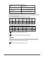
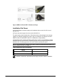
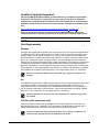
NOTICE: Varian, Inc. was acquired by Agilent Technologies in May 2010. This document is provided as a courtesy but is no longer kept current and thus will contain historical references to Varian. For more information, go to www.agilent.com/chem. Varian 310/320-MS LC/MS Quadrupole Mass Spectrometer Pre-installation Instructions Checklist NOTE: Do not unpack the shipping cartons. Check off each checklist box after satisfying each requirement as described in the instructions. All requirements must be met before requesting installation. NOTE: If the site is not ready for installation when the Varian Representative arrives, Varian, Inc. reserves the right to invoice for the Representative’s time. REQUIREMENTS ; Installation site is in compliance with all relevant safety regulations. User Representative will be available during the installation and Varian certification period. Entrance to the installation site is at least 92 cm (36 in.) wide. Bench space is sufficient. Bench can support system weight. Bench does not vibrate. Exhaust system is suitable. Temperature maintained between 16 and 30 °C, (61-86 °F). Relative humidity maintained between 20 and 80%. Installation site is free of excessive particulate matter. Specified electrical supply and power outlets are installed. Nitrogen gas (at least 99% pure), regulator, and gas lines are installed. Air (less than 0.1 ppm hydrocarbons), regulator, and gas lines are installed. Argon (greater than 99.0% pure), regulator, and gas lines are installed. Argon required only for triple quadrupole instruments. Materials and solvents of specified grade are on site. 310-MS ONLY: Syringe pump similar to the Harvard syringe pump (Varian part number 2732070100). Shipping cartons inspected for damage. If there was any damage, the damaged shipping carton procedure was completed. Requesting Installation After preparing the site, contact the Customer Service office in your region to schedule installation. 395411000: Rev. 5 1 of 14 Pre-installation Instructions Contents Introduction ...................................................................2 Safety ......................................................................2 Before the Installation ...................................................3 User Representative ................................................3 Entrance ..................................................................3 Bench Space and Load ...........................................3 Vibration ..................................................................6 Exhaust System .......................................................7 Temperature ............................................................7 Humidity ...................................................................8 Particulate Matter ....................................................8 Power Requirements............................................... 8 Installation Site Power ........................................... 10 Qualified Computer Equipment ............................. 11 Gas Requirements ................................................ 11 Materials and Solvents .......................................... 12 When the LC/MS Arrives ............................................ 13 Inspecting the Shipping Cartons ........................... 13 Unpacking and Installing ....................................... 14 Spare Parts ................................................................. 14 Preventive Maintenance ............................................. 14 Trademark Acknowledgment ...................................... 14 Introduction The Pre-installation Instructions are a guide for each requirement of the checklist. Follow these instructions to ensure that the installation requires no more than the usual three days. Have the completed checklist available to schedule the installation. After the Varian Representative completes the installation, and it is accepted, samples can be analyzed. After meeting all of these requirements, contact the Customer Service office in your region to schedule the installation. The LC/MS operates reliably under carefully controlled environmental conditions. You must provide suitable power sources, operating environment, materials, and solvents. Failures may occur if you use or maintain the system outside of the power and operating environment ranges and limits described in these instructions. The Varian Warranty and Service contract specifically excludes the repair of failures due to such causes. CAUTION All phases of preparing the installation site must conform to local safety, electrical, and building codes. These codes take precedence over any recommendations in these instructions. The customer is responsible for compliance. Safety Safety is the most important consideration for instrument use. Determine if the installation site complies with all relevant safety regulations. ; 395411000: Rev. 5 Check the checklist box: Installation site is in compliance with all relevant safety regulations. 2 of 14 Pre-installation Instructions Before the Installation User Representative Schedule the installation when the User Representative will be available. One of the important duties of the Varian Representative is to familiarize the User Representative with the basic functions of the LC/MS. ; Check off the checklist box: User Representative will be available during the installation and Varian certification period. Entrance Before arranging delivery of the LC/MS, determine that there is sufficient clearance to move the shipping cartons to the installation site. The largest shipping carton is 72 cm (28 in.) wide by 92 cm (36 in.) long. If the cartons are to be moved with the pallet, at least 92 cm (36 in.) clearance is needed. Allow additional room for maneuvering the shipping containers around corners and through doors. ; Check the checklist box: Entrance to the installation site is at least 92 cm (36 in.). CAUTION The MS, foreline pump(s), and LC are heavy. To prevent personal injury, use appropriate moving and lifting techniques. Bench Space and Load Use the following information to plan the layout of your LC/MS. The Varian Representative will unpack the cartons and put the modules on the bench. Although the figures show a 320-MS, the information also applies to a 310-MS. Figure 1 and Figure 2 show suggested layouts for the LC/MS with the 212-LC and different autosamplers. The tables after the figures provide information about bench space and load. The bench must be strong enough to support the weight of all modules, wide enough for all modules, and at least 84 cm (33 in.) deep for the MS. 395411000: Rev. 5 3 of 14 Pre-installation Instructions 212-LC and ProStar 430 Figure 1 shows a possible layout for the LC/MS with the 212-LC pumps and the ProStar 430 AutoSampler. The autosampler belongs on the side of the 212-LC pumps, not on top. NOTE: Do not stack an autosampler on top of the 212-LC pumps. Figure 1 Suggested Layout with 212-LC and ProStar 430 Table 1 and Table 2 list the dimensions and weights of the modules in Figure 1. Table 1 Bench Space Bench Width Solvents 212-LC ProStar 430 320-MS or 310-MS CPU Monitor and Keyboard Total cm 30.5 26 28 53.5 18.6 43.8 200.4 cm in. 12 10.5 11 21 7.4 17.25 79.15 in. Table 2 Bench Load 395411000: Rev. 5 Bench Load Solvents 212-LC ProStar 430 320-MS or 310-MS Monitor, CPU and Keyboard Total kg 8 14.5 21 61 17.9 122.4 kg lb 18 32 46 134 39.4 269.4 lb 4 of 14 Pre-installation Instructions 212-LC and HTS PAL Figure 2 shows a possible layout for the LC/MS with 212-LC pumps and CTC HTS PAL Autosampler. Figure 2 Suggested Layout with 212-LC and HTS PAL Table 3 and Table 4 give the dimensions and weights of the modules in Figure 2. Table 3 Bench Space Bench Width Solvents 212-LC 320-MS or 310-MS with HTS PAL CPU Monitor and Keyboard Total cm 30.5 26 53.5 18.6 43.8 172.4 cm in. 12 10.5 21 7.4 17.25 68.15 in. Table 4 Bench Load Bench Load Solvents 212-LC 320-MS or 310-MS with HTS PAL Monitor, CPU, and Keyboard Total kg 8 14.5 71 17.9 111.4 kg lb 18 32 162 39.4 251.4 lb The system requires a clean, flat bench. The bench must have enough space for the modules, the mouse, solvent bottles, and such, see Table 5. The bench must be strong enough to support the weight of the modules. The area under the bench must be large enough for the foreline pump(s). If the bench is against a wall, drill a hole large enough for the vacuum tubing of your pump(s) through the rear of the bench. See Table 8 for more information. Refer to the Varian LC Systems Pre-installation Instructions, part number 391483100, for information about LC modules. Plan to put the monitor and keyboard on the same bench as the LC/MS. If the plan is to use a separate bench, position them within 3 m (10 ft) of the rear of the LC/MS. The CPU can go on or under the bench. 395411000: Rev. 5 5 of 14 Pre-installation Instructions Table 5 Additional Bench Space Requirements Function Space Allowance Provide space for air circulation, gas lines, and electrical connections. 15 to 30 cm (6 to 12 in.) behind the system. Dissipate room heat and allow for routine maintenance. At least 76 cm (30 in.) above the system. Analytical Systems only: Provide space for solvent bottles. At least 30 cm (12 in.) to side of the LC. Decide how to arrange the modules. Use Table 6 and Table 7 to determine the width of the bench and the load the bench must support. Regardless of module, the bench must be at least 84 cm (33 in.) deep for the MS. Table 6 Bench Width Calculation Worksheet for Your System Bench Width ___-LC AutoOther 320-MS or sampler Components 310-MS CPU Monitor and Keyboard Total cm ______ ______ ______ 53.5 18.6 43.8 ___cm in. ______ ______ ______ 21 7.4 17.25 ____in. Table 7 Bench Load Calculation Worksheet for Your System Bench Load ___-LC Autosampler kg ______ _______ ______ lb ______ ______ ______ ; ; Other 320-MS or Components 310-MS Monitor, CPU, and Keyboard Total 61 17.9 ____kg 134 39.4 ____lb Check the checklist box: Bench space is sufficient. Check the checklist box: Bench can support system weight. Vibration Ensure that the benches are free from vibrations, especially those caused by equipment in adjoining locations. Because the foreline pump(s) vibrates during operation, it belongs on the floor below the LC/MS, not a on the bench with the LC/MS. ; 395411000: Rev. 5 Check the checklist box: Bench does not vibrate. 6 of 14 Pre-installation Instructions Foreline Pump(s) The following table has information about the foreline pump(s). Table 8 Foreline Pump Information Item Pump(s) Weight or Load for optional foreline pump bench 72 kg or 160 lb Diameter of hole in wall, if needed 2 each 5.8 cm (2.3 in.) Width 35.6 cm (14 in.) Depth 52.1 cm (20.5 in.) Height 48.3 cm (19 in.) Vacuum line length 2 each 1.8 m (6 ft) Power cord length 2.0 m (6 ft and 7 in.) Serial cable length 2.7 m (9 ft) Dedicated circuits 1 for each pump Power 10A, 200-240V ac Power cord plug CEE 7/7 or NEMA 6-15P Exhaust System Do not put the foreline pump(s) in an enclosed space. Foreline pumps exhaust most compounds introduced into the MS and small amounts of oil vapor. Provide an adequate fume exhaust system for the outlet of each foreline vacuum pump. Each foreline pump must be vented at least 2 L/min. The API spray chamber must be vented at least 12 L/min to a separate vent line. Ensure that the exhaust system does not pull a vacuum on the API chamber. Consult local regulations for the proper method of exhausting the fumes. ; Check the checklist box: Exhaust system is suitable. Temperature The optimal operating temperature is between 16 and 30 °C (61-86 °F). NOTE: As installation site temperature increases, system reliability decreases due to heat generated by electronic components during operation. This heat must dissipate to the surrounding air for reliable operation. The airflow around the system must be adequate. The air-conditioning system must maintain a constant temperature (within the operational limits) around the system. Do not place the system near air ducts, windows, or heating and cooling systems. The average steady-state heat load for the MS alone is 6,000 Btu, with a possible short-term heat dissipation of 15,000 Btu during startup. ; 395411000: Rev. 5 Check the checklist box: Temperature maintained between 16 and 30 °C (61-86 °F). 7 of 14 Pre-installation Instructions Humidity The relative humidity of the operating environment must be between 20 and 80%, with no condensation. Operating the LC/MS at a very low humidity may result in the accumulation and discharge of static electricity, shortening the life of electronic components. Operating the system at high humidity may create condensation and result in short circuits. Varian recommends using a combination temperature and humidity monitor in your installation site. ; Check the checklist box: Relative humidity maintained between 20 and 80%. Particulate Matter Your installation site must not have excessive dust, smoke, or other particulate matter. Particulate matter may block airflow vents causing the electronics to overheat. ; Check the checklist box: Installation site is free of excessive particulate matter. Power Requirements 212-LC Power Input: 85-264V ac; 47-63 Hz; 60 Watts 100VA 216-LC 115V ac; +15/-20%; 50/60 Hz; 250VA 230V ac; +15/-20%; 50/60 Hz; 250VA (For UPS, assume 250W) For 115V ac: one 5.0 AT-fuse (5 x 20 mm, IEC 127) For 230V ac: one 2.5 AT-fuse All fuses supplied with the 216-LC instrument are UL-listed and CSA-certified. The 216-LC must be used with appliances and power sources that have the proper protective grounding. 310/320-MS The 310/320-MS MS requires a separate circuit, and the outlet must have adequate amperage capacity and a reliable ground. The power source must be clean and capable of providing up to 220-240V ac, 50/60 Hz ±3 Hz, 1.0 kW. 395411000: Rev. 5 8 of 14 Pre-installation Instructions 310/320-MS LC/MS The 310/320-MS LC/MS requires the following: Table 9 301/320-MS LC/MS Circuits, Power Plug and Outlet Types Table 9 lists the circuits, power plug and outlet types of the 310/320-MS LC/MS. Component Circuit Power Plug and Outlet type MS 1 each 220V US: 1 each NEMA 6-15P EU: 1 each CEE 7/7 plugs Foreline pump 2 each 220V US: 1 each NEMA 6-15P EU: 1 each CEE 7/7 plugs Computer 1 each 110V US: 1 each NEMA 5-15P 1 each 220V US 1 each NEMA 6-16P EU: 1 each CEE 7/7 plugs LC modules 110V or 220V see appropriate user manual Table 10 has the power requirements for modules of the 310/320-MS LC/MS. Table 10 LC/MS Power Requirements Module Max Current Draw (Amps) 200-240V ac 320-MS or 310-MS Foreline pumps 5 5 per pump Use a separate dedicated power source for HPLC modules and additional instruments and equipment. Never plug the mass spectrometer and the chromatograph into the same power source or the power source may overload. Never use the free outlet on any of the power sources for equipment that draws more than 2A. Table 11 has information about the power cords and plugs. Table 11 MS and Foreline Pump(s) Power Cords Module 500-MS Foreline Pump(s) Power Cord 1 each 2.5 m (8 ft) 2 each 2.0 m (6 ft 7 in.) Power Plug 1 each CEE 7/7 plugs 2 each CEE 7/7 plugs The power cables for the CPU, monitor, and printer are approximately 2.13 m (7 ft) long. Figure 3 shows the power plug and outlet types. CAUTION 395411000: Rev. 5 Replacing or substituting power cords or plugs must be done with strict compliance with all regulations, including electrical codes, power cord color coding, and appropriate regulatory agency certification marks. 9 of 14 Pre-installation Instructions Figure 3 NEMA 5-15P and CEE 7/7 Outlets and Plugs Installation Site Power In the United States, the power supply to the installation site must be 100-120V ac and 200-240 V ac. In Europe, the power supply to the site must be 200-240V ac The power supply must be stable (free of fluctuations due to slow changes in the average voltage or to changes resulting from surges, sags, or transients). The voltage must meet EN/IEC 61000-4-5 and EN/IEC 61000-4-11 standards for voltage stability. A measured ground to neutral potential of greater than 3 volts ac or dc indicates grounding problems that may need correction. Evaluate any power source suspected of having noise problems with a recording-type power line monitor before operating the system. NOTE: If concerned about the quality of the power, install an uninterrupted power supply, or a power conditioner or both, see Table 12. Table 12 Maximum Power Consumption Maximum Power Consumption Module 320-MS or 310-MS without pumps 1200VA 320-MS or 310-MS with foreline pump(s) 3200VA ; 395411000: Rev. 5 Check the checklist box: Specified electrical supply and power outlets are installed. 10 of 14 Pre-installation Instructions Qualified Computer Equipment If the Varian MS Workstation software is to be installed on a computer not purchased from Varian, the customer is responsible to ensure that the computer is adequately equipped and compatible with the operation of the data system and its communication interfaces. Please check the current list of requirements, available at the following web site. http://www.varianinc.com/cgi-bin/nav?products/chrom/gcms/msws_computer_req Varian does not guarantee the function of the Varian MS Workstation software on computer hardware or operating systems that do not meet the specified requirements. NOTE: Contact your Sales Representative for a list of qualified equipment or for more information. Gas Requirements Nitrogen A nitrogen gas supply that can provide up to a maximum of 12 L/min of gas regulated at 80 psi is sufficient for ESI or APCI operation for one LC/MS. If there is more than one LC/MS, use a nitrogen supply that can deliver a maximum of 18 L/min. The nitrogen must be at least 99% pure with less than 0.1 ppm hydrocarbons and less than 1% oxygen. It must be clean and dry with a −40 °C dew point. Use a nitrogen generator, or a liquid nitrogen boil-off to supply the nitrogen gas. All nitrogen generators require regular maintenance. The customer is responsible for setting up the preventive maintenance procedures and schedules (contact the nitrogen generator manufacturer). Any MS problems caused by poor gas quality are not covered by the Varian Warranty. It is the responsibility of the customer to conform to all regulations regarding the installation and operation of the gas system. The nitrogen supply uses ¼ in. connectors. ; Check the checklist box: Nitrogen gas (at least 99% pure), regulator, and gas lines are installed. Air A compressed air gas supply, capable of providing up to 2 L/min of gas regulated to 80 psi with a two-stage regulator, is required as a nebulizing gas for negative ESI. The customer is responsible to conform to all regulations for the installation and operation of the gas system. The air must be clean and dry, with less than 0.1 ppm total hydrocarbons, including methane, and have a −40 °C dew point. The air supply uses ¼ in. connectors. ; Check the checklist box: Air (less than 0.1 ppm hydrocarbons), regulator, and gas lines are installed. CID Gas (triple quadrupole only) Argon is required as collision gas for MS/MS work with triple quadrupole instruments. The argon supply uses 1/8 in. connectors. Use a two-stage 0-100 psi pressure regulator with a stainless steel diaphragm. The purity of the argon must be greater than 99.0%. ; 395411000: Rev. 5 Check the checklist box: Argon (greater than 99.0% pure), regulator, and gas lines are installed. Argon required only for triple quadrupole instruments. 11 of 14 Pre-installation Instructions Materials and Solvents The Varian Representative will prepare solutions to tune and evaluate the LC/MS. Please supply the materials Table 13 and the solvents on Table 14. Table 13 Materials Materials Quantity (each) Item 2 50 mL clean and new volumetric flasks 2 1 L clean and new bottles for mobile phase reservoirs 1 1 L or larger bottle for LC/MS waste 2 10 mL clean and new volumetric flask 2 100 mL clean and new volumetric flask 1 Pipette 100 to 1000 µL and tips 1 Pipette 20 to 200 µL and tips 1 50 mL clean and new volumetric flask (for optional APCI) 1 500 clean and new volumetric flask (for optional APCI) 1 310-MS ONLY: Syringe pump similar to the Harvard syringe pump (Varian part number 2732070100). Table 14 Solvents for ESI or APCI Solvents for ESI or APCI Quantity (each) Solvent 2 4-liter bottles HPLC grade or better water, new and unopened 2 4-liter bottles HPLC grade or better, acetonitrile, new and unopened Additional tubing is required to complete installation. Most of this tubing is included in the accessory kits of the LC modules. Additional tubing (PEEK® or stainless steel) may be required for installation of special valves or modules. For most analytical HPLC systems, use 1/16 in. tubing with an ID of 0.005 in. Use 0.005 in. ID or smaller tubing downstream of the sample injector and autosampler to prevent peak broadening. Keep tubing as short as possible to prevent peak broadening and to minimize run time. ; 395411000: Rev. 5 Check the checklist box: Materials and solvents of specified grade are on site. 12 of 14 Pre-installation Instructions When the LC/MS Arrives Inspecting the Shipping Cartons After the LC/MS arrives, carefully inspect the exterior of the shipping cartons for evidence of any damage that might have occurred during shipment. Inspect the cartons for the following: • Water stains. • Cuts, punctures, or deep indentations. • Crushed corners or excessively abraded edges. • Blue beads in the Tip (N) Tell arrow point. One Tip (N) Tell indicator label is on the exterior of each shipping carton. Read and follow the instructions on the label. If the Tip (N) Tell arrow point is blue, the carton was on its side or tipped in transit and instrument damage may have occurred. If no external damage is apparent, sign the receiving documents, “Received but not inspected” to indicate that the cartons were not opened. If the customer receive obviously damaged materials without noting the damage on the receiving documents, Varian will not accept the liability Do not open any shipping cartons. The Varian Representative opens them during installation. Move the shipping cartons to a warm, dry, and secure area near the installation site. If a shipping carton shows evidence of damage, do the following procedure: 1. Report the conditions to the carrier when you receive the shipment. 2. Note the damage on all copies of the shipping documents. 3. Write a brief description of the damage. 4. Ask driver to sign next to your comments to signify agreement with the observations. 5. Contact the appropriate Varian office to report the damage. Systems are shipped either FOB Varian or FOB Destination. The manner of shipment determines who is responsible for filing a claim against the carrier if the system was damaged in transit. Most systems are shipped FOB Varian, so any damages incurred in shipment are the responsibility of the purchaser and the carrier. Contact the Varian office for assistance with filing claims and billing repairs. If the system ships FOB Destination, contact the Varian office, and that office files a claim against the carrier. ; 395411000: Rev. 5 Check the checklist box: Shipping cartons inspected for damage. If there was any damage, the damaged shipping carton procedure was completed. 13 of 14 Pre-installation Instructions Unpacking and Installing The Varian Representative will review the Pre-installation Checklist with the customer to ensure that the site requirements were met. The Varian Representative will unpack and install the instrument and demonstrate the fundamental operation and maintenance procedures. The User Representative must be present during the installation. The Varian Representative will demonstrate that the system meets the performance specifications, which are on the data sheet and any additional criteria explicitly written into the sales contract. Plan to analyze samples only after the installation is complete and the conditions of delivery accepted. The process requires at least three days. Spare Parts The 310/320-MS LC/MS and GC/MS Quadrupole Hardware Manual, part number 395417900, has a list of spare parts for routine operation. Preventive Maintenance The customer is responsible for performing routine and preventive maintenance of the LC, autosampler, MS, and data system. If using a nitrogen generator, perform the preventive maintenance to ensure that the nitrogen supply is clean and dry. Any instrument problems resulting from a contaminated gas supply are billable and not included in the Varian Warranty. Perform regular preventive maintenance to increase the life of the system, to maximize system uptime, and to optimize system performance. Refer to the 310/320-MS LC/MS and GC/MS Quadrupole Hardware Manual for details. The Varian Representative will describe and demonstrate these procedures during the installation. Trademark Acknowledgment Microsoft® and Windows® are registered trademarks of Microsoft Corporation. PEEK™ is a registered trademark of the Victrex PLC Company, Lancashire, England. Other brand and product names are trademarks or registered trademarks of their respective holders. 395411000: Rev. 5 14 of 14 Pre-installation Instructions