1
GE Transportation Systems
Global Signaling
PMD-4/4R
System Operation and Maintenance
PN: 100140-010
T
AF
DR
© 2015 GE Transportation Systems Global Signaling, LLC. All rights reserved. The information contained in this publication is the
property of GE Transportation Systems Global Signaling, LLC ("GETS") and is disclosed in confidence. This publication is intended
for use by GETS customers solely for purposes of operating, training and performing routine maintenance of purchased or licensed
GETS products, and it shall not be reproduced, redistributed, retransmitted, translated, abridged, adapted, condensed, revised or
otherwise modified, in any form, in whole or in part, or used for any other purpose or disclosed to others, without the express written
consent of GETS. However, if a GETS customer (“Customer”) requires additional copies of this document or portions thereof for
internal use, GETS hereby grants to Customer a limited right to reproduce this publication, in whole or in part, and Customer agrees
to use such authorized copies (“Copies”) solely for its intended purposes. Any Copies made under this limited reproduction right
shall contain this notice and any other legal notices appearing in this publication. The Customer shall be responsible for complying
with U.S. export control laws with respect of distribution of all Copies.
GETS and Customer agree that the information contained herein does not purport to cover all details or variations in GETS products
or to provide for every possible contingency with installation, operation or maintenance. Should further information be desired or
should particular problems arise that are not covered sufficiently for the user’s purposes, the matter should be referred to GETS. Any
applicable Federal, State or local regulations or company safety or operating rules must take precedence over any information or
instructions given in the Technical Documentation. GETS has no obligation to keep the material up to date after the original
publication.
GE TRANSPORTATION SYSTEMS GLOBAL SIGNALING, LLC EXPLICITLY DISCLAIMS ALL WARRANTIES OF ACCURACY,
MERCHANTABILITY OR FITNESS FOR ANY PURPOSE IN CONNECTION WITH THIS PUBLICATION AND USE THEREOF.
Reproduction and Use Restrictions Agreement
The information contained in this Technical Manual (the “Document”) is the property of GE Transportation Global Signaling (“GETSGS”)
and is protected by copyright and other intellectual property laws. Any unauthorized use or reproduction of this Document without the
prior written consent of GETSGS, whether in hard copy or in an electronic form, is strictly prohibited [except as otherwise set forth below].
Notwithstanding the foregoing, GETSGS hereby grants to the purchaser of the GETSGS equipment, or licensee of the GETSGS software
(such purchaser of licensee referred to herein as “You”), to which the Document pertains, the following limited reproduction rights. By
reproducing any portion of the Document, You expressly agree to the following terms and conditions. You may make additional copies
of the Document solely for use in connection with the GETSGS equipment or GETSGS software to which it pertains, provided that each
copy is a complete copy and does not alter the content or meaning of the Document in any way, and provided further that each such
copy preserves unaltered all trademark, copyright, patent designations and proprietary or confidentiality notices contained therein,
including this Reproduction and Use Restrictions Agreement. Any other use or reproduction of any portion of the Document without the
prior written authorization of GETSGS is expressly prohibited.
Without limiting any other rights or remedies of GETSGS, in the event that You or any of Your employees, agents or contractors copies
any portion of the Document in violation of this Reproduction and Use Restrictions Agreement, You agree to indemnify, defend and hold
harmless GETSGS from and against any and all claims, damages, losses, liabilities and expenses (including reasonable attorney’s fees)
that may be incurred or awarded by reason thereof.
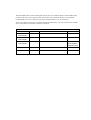
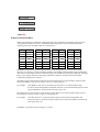
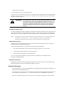
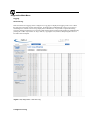
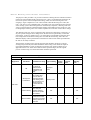
Revision History
This document supersedes all previously issued versions, providing new or revised information. The most recent publication can be
determined by comparing the last three characters at the end of the part number and the date issued.
PMD-4/4R
System Operation and Maintenance
Part Number100140-010-AA0
Revision
Level
Date
Issued
General Description of Changes
AA0
xx/xx/xx
Initial Release
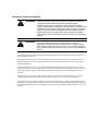
Important Information
Conventions
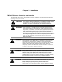
Safety Alert Symbols
The
symbol indicates that important personal safety information follows. Carefully read this text for
the warnings information it contains. The signal word next to each safety alert symbol is defined as:
WARNING
CAUTION
Indicates a potentially hazardous situation which, if not avoided, could
result in death or serious injury. Reference SRAC2.
Indicates a potentially hazardous situation which, if not avoided, may
result in minor or moderate injury. This signal word may also be used
to identify unsafe practices.
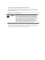
Static Sensitive Symbols for Equipment Handling Instructions
The
and
symbols indicate important handling guidelines established by the AREMA (American
Railway Engineering and Maintenance of Way Association) for proper handling of electronic equipment
modules and sensitive components for the prevention of potential damage that could be caused by ESD
(electrostatic discharge) during routine maintenance, handling and transportation.
Module
ESD
Notice
To protect against ESD damage to electronic equipment containing
modules, follow the field procedures in AREMA C&S Manual, Part
11.4.5. Failure to use protective measures could result in permanent
equipment damage, either immediate or latent, when handling
modules.
Component
ESD
Notice
To protect against ESD damage to electronic equipment containing
components, follow the field procedures in AREMA C&S Manual, Part
11.4.5. Failure to use recommended protective measures could result
in permanent equipment damage, either immediate or latent, when
handling components.
Important/Notable Information
Important: Indicates an operating procedure, practice, or condition which, if not strictly followed, may
cause equipment damage.
Note: Indicates additional information or emphasizes a topic related to the subject being discussed.
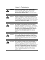
General Safety Instructions
WARNING
It is the railway's responsibility to ensure that only qualified personnel work
on or around this equipment and to prevent any unauthorized tampering. To
ensure the highest degree of safety, all personnel are required to
become thoroughly familiar with all personal safety instructions contained in
this manual. Successful and safe operation of this equipment is dependent
upon correct handling, operation, maintenance, repair, and application of
associated railroad equipment. Deliberate misuse or abuse of electronic
safety equipment may result in injury or death.
No information in this manual supersedes or replaces your railroad’s
operating rules. If there is a difference in instructions between this manual
and the railroad’s operating rules, follow the most restrictive instruction.
Railroad Configuration Management Procedures must ensure that all PMD4/4R units are configured with the proper revisions of modules and firmware
(both application and executive) and that updates are completed in a timely
manner when made available by GE Transportation Systems Global
Signaling. Operating with incorrect firmware may result in death or serious
injury. Timely is defined as without undue delay per 49 CFR 236.1023(j).
Updating or modifying modules, firmware, and values (both application and
executive) must be performed by qualified personnel that are physically
present at the site being updated.
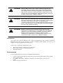
Railroad Configuration Management Procedures must ensure that the proper
values are set for each crossing parameter, vital timer, vital configuration
setting (vital soft switches), PTC Wireless Crossings vital parameters, and
vital remote parameter in their PMD-4/4R units. Incorrect settings may result
in death or serious injury.
Deliberate misuse or abuse of electronic components may cause
personal injury or death.
To avoid personal injury or death due to collision, follow your railroad's
operating rules while moving a locomotive with inoperative equipment or
during irregular operating situations.
Track circuit troubleshooting interferes with signal system operation. Always
obtain proper authorization prior to performing track circuit
troubleshooting.
Do not use this equipment until you are sure the application logic is properly
programmed and functionally tested. Test it according to United States DOT
(Department of Transportation) FRA ( Federal Railroad Administration) Code
of Federal Regulation, Title 49 procedures, or other equivalent tests, as
deemed necessary by other appropriate regulatory agencies.
If any failure of the equipment is detected, it is the railroad's responsibility to
ensure the failure is reported in a timely manner. Once the failure is
reported, the appropriate steps must be taken to ensure the equipment is
repaired or replaced promptly. Failure to report and repair unit/module in a
timely fashion may result in death or serious injury. Timely is defined as
`without undue delay per 49 CFR 236.1023(j).
Failure to follow the instructions in this manual may result in short or long
warning times. Short warning times may result in death or serious injury.
Reference SRAC2.
WARNING
If a train stops on the approach and accelerates toward the crossing,
the PMD-4/4R may not provide a minimum 20 seconds of warning
time. Short warning times could result in death or serious injury.
If a train accelerates toward the crossing after the PMD-4/4R has
activated the warning system, the PMD-4/4R may not provide a
minimum 20 seconds of warning time. Short warning times could
result in death or serious injury. Reference SRAC2.
FCC Compliance
This equipment has been tested and found to comply with the limits for a Class A digital
device, pursuant to part 15 of the FCC rules. These limits are designed to provide reasonable
protection against harmful interference when the equipment is operated in a commercial
environment. This equipment generates, uses, and can radiate radio frequency energy and, if
not installed and used in accordance with the instruction manual, may cause harmful
interference to radio communications. Operation of this equipment in a residential area is likely
to cause harmful interference in which case the user will be required to correct the interference
at his own expense.
CAUTION
Modifications or changes not expressly approved by GE
Transportation Systems Global Signaling could affect the compliance
of the equipment with the FCC Rules and void the user’s authority to
operate the equipment.
Foreword
There are no electronic components or modules in the PMD-4/4R system that can be repaired by the
customer. Defective or damaged modules should be sent to GE Transportation Systems Global Signaling,
Customer Service Department, P.O. Box 600, Grain Valley, MO 64029-0600.
Technical Support
GE Transportation Global Signaling will accept telephone calls between 7:30 AM and 5:30 PM CST. Call
TOLL FREE (800) 825-7090 regarding installation, maintenance, calibration, adjustment, or repair of any
components.
Scope
GE Transportation Global Signaling, Technical Information Department under the direction of the
designated equipment Product Manager, issues this document. The manual introduces you to the PMD4/4R system by providing specific information related to Introduction, Installation, Parameter Setup,
Adjustment, and Calibration, Maintenance, Troubleshooting, DISPLAY Navigation, Web Graphical User
Interface, Terminal (DCP) Navigation, Retest Guide, Specifications and Appendix . Please read carefully
and thoroughly understand the instructions and processes before making any adjustments or modifications
to the equipment. Carelessness may result in loss of life or property damage.
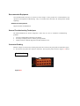
How to Order an Additional Copy or a Revised Printing
Additional copies of this document may be ordered by directing all correspondence to GE Transportation
Global Signaling, Customer Service Department, 2712 S. Dillingham Rd., Grain Valley, MO 64029-0600 or
calling (800) 825-7090 or by FAX (816) 650-9501.
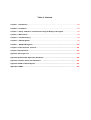
Table of Contents
Chapter 1 – Introduction ..................................................................................................................... XX
Chapter 2 – Installation ....................................................................................................................... XX
Chapter 3 – Setup, Calibration, and Checkout using the Display and Keypad .................................. XX
Chapter 4 – Maintenance .................................................................................................................... XX
Chapter 5 – Troubleshooting .............................................................................................................. XX
Chapter 6 – CDU Navigation ............................................................................................................... XX
Chapter 7 – WebGUI Navigation………………………………………………………………………………..XX
Chapter 8- Telnet Terminal Terminal……………………………..…………………………………………..XX
Chapter 9- Specifications………………………………………………………………………………………..XX
Appendix A Acronym List..........................................................................................................................XX
Appendix B Ethernet/IP Application Guidelines………………………………………………………..…..XX
Appendix C System Timing Considerations. …..…..………………………………………………………XX
Appendix D SSH Command Syntax…………………….…..…………………………………………………XX
Appendix D SRAC…………………………………………………………………………………………………XX
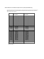
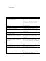
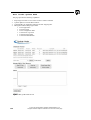
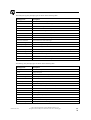
Grade Crossing Location Record
Chassis ID
Warning Time CRC
Location
Milepost
DOT
Version
Executive Software Program
Date
/
CRC
A Processor
B Processor
C Processor
Application Program Name
Checksum
CRC
Track Setup
Approach Frequency
Master/Slave Operation
□ Master
□ Slave
Transmitter Check Value (-7.0 to 13.0 Ohms)
Approach Direction Mode
□ Uni
□ Bi
Lumped Impedance Adjustment Value (-9 to +9)
Auto RX
□ Disabled
□ Enabled
False Shunt Detect setting
□ Disabled
□ Enabled RX
Time (min)
Approach Release setting
□ Disabled
□ Enabled RX
Time (min)
LOS Time (seconds)
Approach Maintenance
Phase Compensation Value (0 to 10 degrees)
Ballast Compensation Value (50 to 250)
Island Setup
Island Type
□ External
□ Internal
Island Setup (When Internal is selected)
Island Frequency (KHz)
□ 0 □ 4.0 □ 4.4 □ 4.9 □ 5.4 □ 5.9 □ 6.4 □ 7.1 □ 7.7 □ 8.0
Island LOS (seconds)
□ .5 □ 2.0 □ 4.0
Island Fault Setting
□1 □2
/
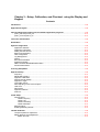
Chapter 1 – Introduction
Contents
Introduction ........................................................................................................................................... XX
PMD-4/4R General Description ............................................................................................................. XX
System Block Diagram .......................................................................................................................... XX
Theory of Operation .............................................................................................................................. XX
Island Operation ........................................................................................................................... XX
High Signal ................................................................................................................................... XX
Low Phase Detection .................................................................................................................... XX
Chassis Components .......................................................................................................................... XX
Chassis Connectors and Power Switch ......................................................................................... XX
Chassis Fuses .............................................................................................................................. XX
Ethernet Ports............................................................................................................................... XX
Display and Keypad ...................................................................................................................... XX
Front Panel LEDs ......................................................................................................................... XX
Processor Operation ............................................................................................................................. XX
CPU A and CPU B ....................................................................................................................... XX
CPU C.......................................................................................................................................... XX
Ethernet Interface ......................................................................................................................... XX
Error Log ...................................................................................................................................... XX
Recorder Log ............................................................................................................................... XX
Configuration Log ......................................................................................................................... XX
Train Data Log ............................................................................................................................. XX
Train Record Log.......................................................................................................................... XX
System Event Log ........................................................................................................................ XX
Ring Status Log ............................................................................................................................ XX
PMD-4/4R Crossing Track Interface...................................................................................................... XX
Approach transmitter .................................................................................................................... XX
Master/Slave ................................................................................................................................ XX
Island Transmitter ......................................................................................................................... XX
Transmit and Receive Sense Circuitry .......................................................................................... XX
Digital Signal Processors .............................................................................................................. XX
Vital Inputs and Outputs ......................................................................................................................XX
Isolated DC/DC Converter.............................................................................................................XX
Vital Inputs ....................................................................................................................................XX
Vital Outputs .................................................................................................................................XX
Chapter 1 – Introduction
Introduction
This manual contains information describing the PMD-4/4R system configured for highway/rail grade
crossing applications. Included in this manual are introduction (including theory of operation), installation,
unit description, setup and calibration, maintenance and troubleshooting for the PMD-4/4R.
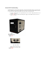
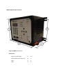
PMD-4/4R General Description
The PMD-4/4R system is crossing control system used to detect approaching trains. Capabilities of the
PMD-4/4R include: Motion detection control, crossing island train detection, vital inputs monitoring and
vital relay drive output control. The PMD-4/4R has provisions for expansion to wireless crossing control
and prediction capabilities with the optional selective function upgrade.
The PMD-4/4R has a built in recorder that logs time-stamped vital and non-vital events as well as state
changes, crossing performance data, and failures/reset information. All recorded events are user printable
both track-side and in the office.
The PMD-4/4R consists of a central processor, track and IO controllers, communications interface and a
LCD display with keypad/button interface. Front panel indicators display module health status, and
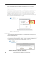
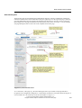
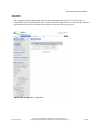
indicators for monitoring active I/O signals. The Web Graphical User Interface (web GUI) or LCD display
serve as the man/machine interface for system installation/setup, parameter adjustment, and system
testing/troubleshooting. The Web GUI is operated by a separate computer / PDA device running an Internet
Explorer (or compatible) web browser.
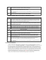
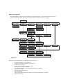
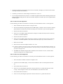
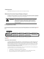
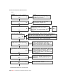
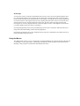
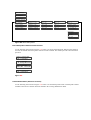
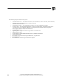
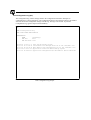
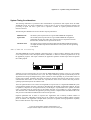
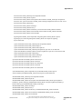
System Block Diagram
The PMD-4/4R System Block Diagram shows how the PMD-4/4R internal modules interconnect, and the
main inputs and outputs. The PMD-4/4R System Block Diagram is shown in Figure X-X below.
Figure X-X
Theory of Operation
The PMD-4/4R detects train movement toward a railroad/highway intersection by monitoring a controlled AC
signal that it transmits to the railroad track. Two sets of leads are required to complete the track circuit. One
set of leads is used to transmit the signal onto the track and another set of leads is used to monitor/receive
the signal on the rail. The transmitter and receiver leads are spaced apart and the track between the leads is
called the Island. Both the voltage (RX) and phase angle of the received signal are measured. RX is used to
determine train speed and distance. Phase angle is used to determine ballast conditions.
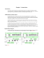
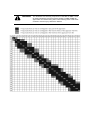
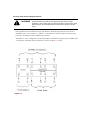
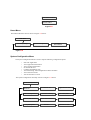
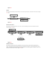
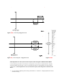
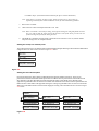
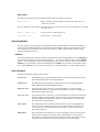
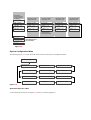
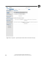
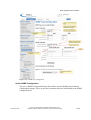
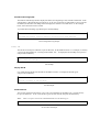
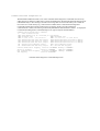
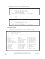
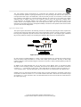
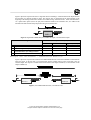
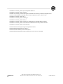
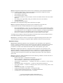
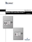
The distance that a train can be detected on each side of the island is called the approach. The length of the
approach is a function of the maximum allowable train speed at that location per railroad operating rules
and the minimum acceptable warning time. For an unoccupied approach, RX is adjusted to 100. When a
train moves inbound on the approach, RX decreases linearly in relation to the train’s lead axle location
relative to the crossing. For example, when the train has moved one quarter of the way into the approach
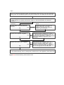
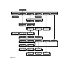
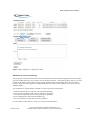
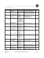
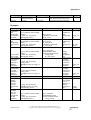
the RX will equal 75. Figure X-X below depicts a train moving through a crossing and following table
describes the sequence of events that occur in response to train movement.
1
2
3
4
5
ISLAND
RX =100
RX =100
MD UP
Train Detected
RX less than 100 and falling
RX rising
RX =0
MD DOWN
RX =0
MD UP
323-0302
Figure X-X
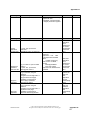
TRAIN POSITION
PMD-4/4R Crossing Subsystem RESPONSE
Position 1 - Inbound train outside the
approach (RX = 100)
Train not detected no response.
Position 2 - Train detection (RX falling)
A train moving inbound on the approach causes a change in the
received voltage level and phase. The rate at which the received
signal changes, is used to determine train speed and anticipated
arrival time at the crossing.
Position 3 - Crossing activated
When sufficient inbound motion is detected or the calculated
arrival time to the crossing equals the selected warning time in
limited predict mode, the PMD-4/4R Crossing Subsystem
activates the crossing warning system.
Position 4 - Train in Island (RX = 0)
The Random Signature Island (RSI) function of the PMD-4/4R
Crossing Subsystem monitors train presence in the Island and
provides positive control of the relay output with a train in the
island circuit.
Position 5 - Train leaves Island (RX
rising)
As the last set of wheels leave the Island, the island circuit
recovers and the PMD-4/4R Crossing Subsystem de-activates
the crossing warning system as the train proceeds outbound.
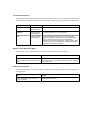
Island Operation
The island is that portion of the track between the transmitter and receiver leads. Motion cannot be detected
when a train is in the Island (i.e. moving between the transmitter and receiver leads) because the train
shunts out the transmitted signal and the receiver voltage is zero. Island occupancy detection is provided by
transmitting and receiving a signal called Random Signature Island (RSI). RSI is an AC signal with a
randomized modulation scheme. The RSI is transmitted and received through the same leads as the
approach signal described previously. The table below describes the RSI transmitter and receiver functions.
RSI Functions
Island Transmitter
•
•
•
Island Receiver
•
•
•
Transmits a short signal burst to the track through the transmitter
leads.
The signal burst is coded with a signature that changes randomly from
one burst to another.
Signal signature consists of changes in the time delay between bursts,
the transmitted frequency of each burst and the number of cycles in
each burst.
Receives the short signal burst from the track through the receiver
leads.
The received signal is used to determine when a train is occupying the
island
Island occupancy is determined when the received signature is not
correct or the signal amplitude is below the minimum threshold.
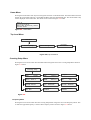
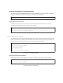
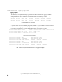
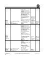
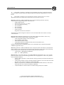
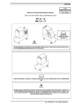
High Signal
A properly configured PMD-4/4R in a crossing configuration will detect an open/broken rail condition
within its approaches to prevent any loss of warning time. At installation, the PMD-4/4R is adjusted so that
an RX of ‘100’ is detected for a clear approach. A High Signal is declared whenever the RX level increases
to a preset value of 110 or above, indicating an open/broken rail condition exists within the approach.
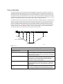
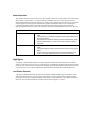
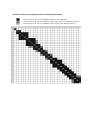
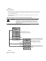
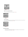
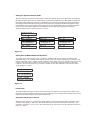
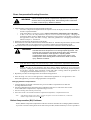
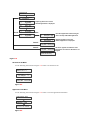
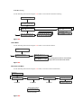
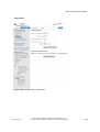
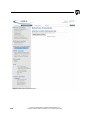
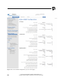
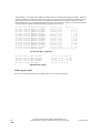
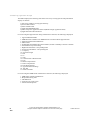
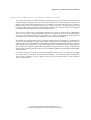
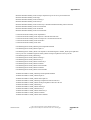
Low Phase Detection
A properly configured PMD-4/4R can detect when a change in ballast conditions has occurred that could
affect RX and result in a loss of warning time. Phase angle is used to monitor ballast conditions. When
phase angle is below the minimum acceptable value for the associated RX level, a Low Phase condition is
declared. The Low Phase threshold versus RX value is shown in Figure X-X below.
40
120
o
o
32 o
HIGH SIGNAL
110
30
100
RX-96
90
80
70
LOW PHASE
RX
60
50
40
30
20
10
56
90
o
80
o
70
o
60
o
o
50
o
40
o
30
o
20
o
10
o
0
o
PHASE ANGLE (DEGREES)
323-0133A
Figure X-X
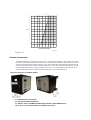
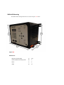
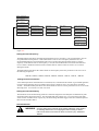
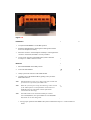
Chassis Components
The PMD-4/4R chassis contains the central processor, track and IO controllers. The On/Off power switch
is located on the left side of the chassis. There are no serviceable parts inside the chassis. Fuses are located
on the front and right side to protect internal circuitry. The chassis has a built in display and keyboard. All
external connections are via WAGO connectors on the sides of the chassis. LEDs on the front are used for
setup and diagnostic purposes. Setup parameters are stored on a memory module on the right side of the
chassis which enables chassis change out without needing to re-enter setup parameters.
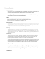
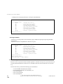
Chassis Connectors and Power Switch
J1 – B12/N12 Power Connector
J2 – Site Specific Memory Module
J3 – Master / Slave on PMD-4/4R & Standby Indicator output PMD-4R only
J16,17 & 18 – Track & Vital Inputs and Outputs Connector
Chassis Fuses
F7 – 10A Main Power Fuse
F5 – 4A Standby XTI Fuse
F1 – 7.5A +5 Volt Power Fuse
F6 – 4A Normal XTI Fuse
F3 – 3A Input Output Module Fuse
F2 – 3A Normal/Standby Module Fuse
F4 – 4A XTI Fuse
Ethernet Ports
1 – Ethernet Port 1 Default 192.168.0.11
2 – Ethernet Port 2 Default 192.168.1.12
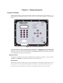
Display and Keypad
The PMD-4/4R front panel has a 4 line 40 character LED high contrast display for viewing and entering information.
The key pad consisted of ten tactile feel buttons labeled 0 to 9 with a Cancel and Enter button. Left/right and up/down
buttons are used for selecting menu option and scrolling the display characters. A home button is available to return to
the main home menu from anywhere in the menu structure.
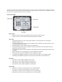
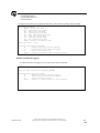
Front Panel LEDs
System LEDs
•
B12/N12 LED is on when power is applied to the B12 and N12 power connector
•
HEALTH LED is on when all internal module health statuses are healthy
Track LEDs
•
High Signal LED will be on when a high signal is detected. The LED will remain on until the High
Signal/Low Phase is reset.
•
Low Phase LED will be on when a low phase condition has been detected. The LED will remain on until
the High Signal/Low Phase is reset.
•
Motion LED will be on when motion is detected on the approach.
•
ATC Enabled LED will be on when the approach track circuit is enabled. This LED will flash when the
approach track circuit is disabled.
•
ITC Enabled LED will be on when the island circuit is enabled. This LED will flash when the island circuit
is disabled.
•
Master LED will be on when the approach circuit is configured as the master.
•
Slave LED will be on when the approach circuit is configured as a slave.
•
Track STBY LED (PMD-4R Only) will be on when the XTI track module is on the standby module.
•
I/O Standby LED (PMD-4R Only) will be on when the Vital I/O module is on the standby side.
Input LEDs
•
ISL LED is on when voltage is applied to the ISL input.
•
RSO LED is on when voltage is applied to the RSO input.
•
AUX1 LED is on when voltage is applied to the AUX1 input.
•
AUX2 LED is on when voltage is applied to the AUX2 input
Output LEDs
•
MDR LED is on when the unit is providing 12 vdc on the MDR output.
•
ISL LED is on when the unit is providing 12 vdc on the ISL output.
•
AXO1 LED is on when the unit is providing 12 vdc on the AXO1 output.
•
AXO2 LED is on when the unit is providing 12 vdc on the AXO2 output.
Processor Operation
CPU A and CPU B
CPU A and CPU B are responsible for the system’s vital application logic processing, communication, and
control of the inputs and outputs and the continual performance of the system safety checks.
User supplied configuration information is used by CPU A and CPU B during application program
execution and is vitally stored in non-volatile memory on the site specific memory module. The unit may be
replaced without loss of the system configuration information.
CPU C
CPU C is responsible for external communications, diagnostics and the user
display and touchpad interface. It also maintains non-volatile diagnostic logging
in the Error, Recorder, Communication, and Configuration logs.
Ethernet Interface
The PMD-4/4R provides two Ethernet ports that support 10BASE-T and 100BASE-T communications and
auto-negotiate with the connected network device for speed selection. The Ethernet ports also auto-detect
straight versus crossover connection types so either cable type can be used.
Error Log
The PMD-4/4R Error Log captures error / system event information when a detected error / event occurs.
The Error Log entries indicate the date and time of the event, the processor that declared the error / event
and a description of the error / event. The PMD-4/4R is capable of storing approximately the most recent
5,000 Error Logs entries.
Recorder Log
The Recorder Log captures the state / state change of application statuses as indicated in the application
program defined by the application design engineer. To record the values of a particular status in the
Recorder Log, the named status must be indicated as a recorded status in the application.
A named status indicated in the application program as a recorded status is logged in the Recorder Log each
time the status changes state along with the date and time of the change. The PMD-4/4R Recorder Log is
sized to record the most recent 100,000 entries of up to 512 Vital and 512 Non-vital recorded statuses.
Configuration Log
The Configuration Log captures parameter / configuration setting changes as they are made to the system
configuration information used by the PMD-4/4R system. When configuration settings are changed, CPU C
captures the change and the date / time of the change in the Configuration Log. The Configuration Log is
sized to capture the most recent 1000 Configuration change events.
Train Data Log
The Train Data log stores 248 millisecond samples of crossing related data from 30 seconds prior to any
MDR Status dropping until 10 seconds after the MDR Status is picked back up. This log stores the last
15,000 entries. Each Train Data Log entry contains the following:
•
•
•
•
•
•
•
•
Time/Date stamp
RX value
Phase value
Island Assignment Status state
MDR Status
AUX Status
RSO Status
Advance Preempt (AP) Statuses
Train Record Log
Each time a train occupies an Island, the PMD-4/4R generates a Train Record Log entry to provide a history
of crossing related information for each train passage. The PMD-4/4R will store the last 5000 train moves in
this log. The following data is logged in each Train Record log entry:
•
•
•
•
MDR Status Mnemonic/Number
Actual Warning time
Predicted Warning Time
Detection Mode
System Event Log
The System Event Log records the current state of any configured ISL, MDR, AUX, RSO, or AP status
when any one of these changes. It also records the current value for RX & Phase of each configured
approach track circuit. The log stores approximately the last 15,000 entries.
Ring Status Log
Each time the MDR drops, the PMD-4/4R generates a Ring Status Log entry to provide information about
the MDR. The PMD-4/4R stores the last 450 entries into this log. Each Ring Status Log entry contains the
following:
•
•
Time/Date stamp
MDR Ring Statuses
PMD-4/4R Crossing Track Interface
The PMD-4/4R provides 2 track circuits for crossing control applications:
•
•
An approach track circuit used for motion detection or constant warning prediction of trains traversing an
approach, and
An island track circuit used to detect the train presence near/within the island.
Approach Transmitter
The Approach Transmitter circuitry provides a continuous sinusoidal signal at various programmable
frequencies to the crossing approach track. It is driven by a sine wave signal generated by either the digital
signal processors or the Master/Slave circuitry. The approach transmitter provides digital gain control of
the output signal. The approach transmitter shares a single interface to the track with the Island
Transmitter.
Master/Slave
The Master/Slave interface allows multiple approach transmitters to be synchronized (PMD-4/4R, XP4 or
HXP-3). If an ATC (Approach Track Circuit) is set for slave mode, the Master/Slave circuitry accepts an
external signal and provides a synchronized signal to drive the approach transmitter. In master mode, the
Master/Slave circuitry provides an external signal that is synchronized to its approach transmitter.
Island Transmitter
The Island Transmitter circuitry provides random signal bursts for train detection within the island limits. It
generates the island signal bursts based on a quasi-random signature bursts received from the digital signal
processors. The transmitter circuitry allows for digital gain control of the output signal for automated
calibration.
Transmit and Receive Sense Circuitry
The Transmit and Receive Sense circuitry samples and digitizes information related to approach transmit
signal, the island transmit signal, and the combined approach/island receive signal. This information is then
sent on to the dual, digital signal processors, for filtering and analysis.
Digital Signal Processors
One DSP (Digital Dignal Processor) drives the approach transmitter while the other DSP drives the island
transmitter. Both of the DSPs:
•
Filter and determine frequency, amplitude, and phase of the approach transmit current and
voltage
•
Filter and determine amplitude and phase of the approach receive voltage
•
Filter and determine amplitude, frequency, and burst length for the island receive signals.
•
Pass this information on to the processor for further processing.
Vital Inputs and Outputs
The PMD-4 system provides the following configuration options:
a. PMD-4: Four general purpose, two wire, Vital Inputs and outputs.
b. PMD-4R: Four general purpose, two wire, Vital Inputs and outputs with I/O redundancy.
Vital I/O is used for monitoring vital inputs and supplying vital outputs according to the application
equations. (The inputs can be used for inputs, Island inputs and other vital controls while the outputs can
be used for vital control of crossing relays or remote crossing starts and other equipment).
Isolated DC/DC Converter
The Isolated DC/DC Converter provides isolation between the supply battery and the vital outputs.
Vital Inputs
The Vital Inputs are redundant general purpose two-wire inputs for the PMD-4/4R. When an input rises
above 8.0 ± 0.5 Volts, it is considered energized. The vital input remains energized until the input
voltage falls below 6.5 ± 0.5 Volts. Vital inputs will accept voltages up to 16.5 Vdc.
With the PMD-4R, if a vital input fails the module transfers to the redundant vital input. If a failure
occurs where internal modules loses the vital input redundancy, the I/O STBY LED is turned off.
Vital Outputs
The vital outputs are redundant general purpose, two-wire outputs for the PMD-4/4R. All PMD-4 Vital
Outputs are capable of driving load impedances of 150 ohms. All PMD-4R Vital Outputs are capable of
driving load impedances of 50 ohms
With the PMD-4R if a vital output fails all the vital outputs are shut down for at least 30 seconds. After
30 seconds the vital outputs are transferred to the redundant vital outputs and they are set back to their
energized or de- energized state. The vital outputs can be forced to switch to the redundant bank using
the keypad. If a failure occurs where internal modules loses the vital output redundancy, the I/O STBY
LED will be turned off.
Chapter 2 – Installation
Contents
PMD-4/4R Shipment, Unpacking, and Inspection ............................................................................ XX
PMD-4/4R Mounting .......................................................................................................................... XX
Chassis Mounting ........................................................................................................................ XX
Chassis Grounding ...................................................................................................................... XX
MDSA-1/-1XS Mounting .............................................................................................................. XX
Connecting System Battery and Track Connections....................................................................... XX
PMD-4/4R Connectors ..................................................................................................................... XX
Power ......................................................................................................................................... XX
Track and I/O .............................................................................................................................. XX
Master/Slave and Standby Indicator ............................................................................................. XX
Wiring Requirements ....................................................................................................................... XX
Transmitter - Receiver Track Lead Length ...................................................................................... XX
Maximum Track Lead Length With an Island ................................................................................ XX
Maximum Track Lead Length Without an Island ............................................................................ XX
Track Connections ........................................................................................................................... XX
Track Bonds ................................................................................................................................ XX
Terminating PMD-4/4R Approaches .................................................................................................. XX
Narrow Band Termination Shunts .................................................................................................. XX
Guidelines for Selecting Overlapping Frequencies When Using the NBS-1 ............................. XX
Guidelines for Selecting Overlapping Frequencies When Using the NBS-2 ............................. XX
FSS (Frequency Selectable Shunts) ............................................................................................. XX
Setting the Operating Frequency ............................................................................................ XX
Wideband Termination Shunts ..................................................................................................... XX
Bypassing Insulated Joints ............................................................................................................. XX
Joint Coupler Applications ............................................................................................................ XX
Non-Coded DC Track Circuits ...................................................................................................... XX
Coded DC, Coded AC, and Non-Coded AC Track Circuits ............................................................ XX
Minimum Distance to Joints When Coupled with TJCs ................................................................. XX
Approach Frequency Selection ....................................................................................................... XX
Frequency Selection Guidelines for Bi-directional Approaches ................................................ XX
Frequency Selection Guidelines For Unidirectional Approaches .............................................. XX
Lightning Protection .......................................................................................................................... XX
Chassis ....................................................................................................................................... XX
Supply Battery ............................................................................................................................. XX
Crossing Track Circuits Surge Protection ...................................................................................... XX
Vital Inputs and Outputs Surge Protection ................................................................................... XX
Interconnect Panels ........................................................................................................................... XX
PMD-1/1B .................................................................................................................................... XX
PMD-2 ......................................................................................................................................... XX
PMD-3/3R .................................................................................................................................... XX
HXP-1/1B/1C/2 ............................................................................................................................ XX
Peripheral Equipment ........................................................................................................................ XX
Chapter 2 – Installation
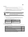
PMD-4/4R Shipment, Unpacking, and Inspection
The PMD-4/4R chassis may be shipped either by itself or installed in a rack assembly with other items,
depending on the system ordered.
CAUTION
If any shipping damage is detected, do not attempt to install or repair
the PMD-4/4R. Contact GETSGS (GE Transportation Global
Signaling) for repair or replacement of the damaged equipment.
WARNING After Installation of an PMD-4/4R unit, adequate testing must be
performed to detect any errors/failures of the application equations,
equipment, or installation. The tests should be performed before the
unit is placed into service and in accordance with standard railroad,
FRA, and/or other regulatory agency rules. The tests should be
performed by qualified personnel that have the knowledge to correctly
and safely discharge the tests. Failure to adequately test the PMD4/4R unit after installation could result in death or serious injury.
Reference SRAC2.
WARNING After Installation of an PMD-4/4R unit, calibration of each Approach
and Island must be performed. Calibration should be performed
before the unit is placed into service and in accordance with standard
railroad, FRA, and/or other regulatory agency rules. Failure to
adequately calibrate the PMD-4/4R unit after installation could result
in death or serious injury. Reference SRAC2.
WARNING During initial installation, proper operation of both the Normal and
Standby system in the PMD-4/4RR configuration must be verified.
Failure to verify proper operation of inactive modules could allow
multiple failures over time to combine, resulting in an unsafe condition
that could result in death or serious injury. Reference SRAC2.
WARNING Unauthorized modification of the PMD-4/4R installation may result in
unsafe conditions that could result in death or serious injury.
Responsibility for physically securing the PMD-4/4R from
unauthorized access lies with the railway authority.Reference SRAC2.
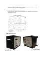
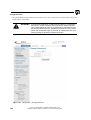
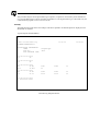
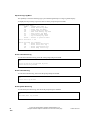
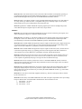
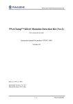
PMD-4/4R Mounting
The PMD-4/4R mounting dimensions are shown in Figure X-X below.
Figure X-X
Dimensions
Maximum Overall Height
A
10.5 “
Distance Between Mounting Holes
B
9”
Depth
C
8”
Width
D
13”
Chassis Mounting
Need to find out about brackets to mount on rack 19 and 24 inch
The chassis may be installed on a standard 19 inch (483mm) rack, wall mounted, or shelf mounted. If rack
mounted, provide at least two inches of space above and below for cooling air flow. Secure the cabinet to
the rack with at least four ½-inch 10-32 machine screws. If wall or shelf mounted, provide at least two
inches of space above the chassis for ventilation.
Insert picture with dimensions
Figure X-X, PMD-4/4R Installation Dimensions.
Chassis Grounding
Insert picture Showing grounding point
MDSA-1/-1XS Mounting
The maximum outside dimensions of the MDSA-1/-1XS are 11 inches (280mm) wide, 7.0 inches (178mm)
high, and 2.85 (73mm) inches deep. The MDSA-1/-1XS may be configured for rack or backboard
mounting. The MDSA-1/1XS mounting dimensions are shown in Figure X-X below.
Figure X-X
The maximum outside dimensions of the MDSA-1/-1XS are 11 inches (280mm) wide, 7.0 inches (178mm)
high, and 2.85 (73mm) inches deep. Refer to Figure X-X for a pictorial representation of the MDSA-1/1XS mounting hole dimensions and locations.
The MDSA-1/-1XS may be configured for rack or backboard mounting. Refer to Figure X-X for the
location of the four holes provided for backboard mounting.
Connecting System Battery and Track Connections
Connect system battery and track connections to the MDSA-1/1XS. The MDSA-1/1X Connections are
shown in Figure X-X below.
Figure X-X
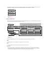
PMD-4/4R Connectors
Power Connector
The PMD-4/4R has one connector, J1 on the left side of the chassis for track equipment power. Connect B12
and N12 from the MDSA-1/1X surge arrestor.
PMD-4/4R J1 Pin Outs
1
B12
2
N12
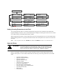
Track and I/O Connectors
The PMD-4/4R has three connectors, J16, J17 and J18 on the bottom left side of the chassis for track
connections and input and outputs. These connectors will be where the track connects to the MDSA-1/1XS
and the inputs and outputs connect to the crossing control equipment.
PMD-4 J16, J17 and J18 Connectors
PMD-4 J16 Pin Outs
1
2
3
4
5
6
7
8
TX+
N/C
TX-
N/C
RX+
N/C
RX-
N/C
1
RSO+
In
2
RSOIn
3
4
AUX1+
In
7
AUX2+
In
8
AUX2In
1
MDROut
2
9
ISL+
In
10
ISLIn
9
10
MDR+
Out
PMD-4 J17 Pin Outs
N/C
5
AUX1In
6
N/C
N/C
PMD-4 J18 Pin Outs
N/C
3
ISL+
Out
4
ISLOut
5
N/C
6
AXO1+
Out
7
AXO1Out
8
N/C
9
AXO2+
Out
10
AXO2Out
9
MDR+
Out
10
MDROut
9
10
ISL+
In
PMD-4R J16, J17 and J18 Connectors
PMD-4R J16 Pin Outs
1
2
3
4
5
6
7
8
TX+
N/C
TX-
N/C
RX+
N/C
RX-
N/C
1
ISL+
Out
2
ISLOut
3
4
AXO1+
Out
7
AXO2+
Out
8
AXO2Out
1
ISLIn
2
7
AUX1In
8
PMD-4R J17 Pin Outs
N/C
5
AXO1Out
6
N/C
N/C
PMD-4R J18 Pin Outs
N/C
3
RSO+
In
4
RSOIn
5
N/C
6
AUX1+
In
N/C
9
AUX2+
In
10
AUX2In
Master / Slave and Standby Indicator Connector
The PMD-4/4R has one connector, J19 on the front on the bottom right side of the chassis for master/slave
connections and the non-vital standby indicator output on the PMD-4R only.
PMD-4 J19 Connector
1
MS+
PMD-4 Connector J19 Pin Outs
2
3
4
5
MSMS+
MSN/C
6
N/C
PMD-4R J19 Connector
PMD-4 Connector J19 Pin Outs
2
3
4
5
STBYMSMS+
MSOut
1
MS+
6
STBY+
Out
Wiring Requirements
WARNING A short circuit between the transmitter and receiver terminals will
bypass the island circuit causing the island receiver to remain
energized while a train is in the island. Failure to detect a train in the
island could result in death or serious injury. Reference SRAC2.
•
Run all wires as directly as possible to minimize wire lengths.
•
Provide a twist of 1 turn per foot for track wires connected to the PMD-4/4R transmitter
terminals.
•
Provide a twist of 1 turn per foot for track wires connected to PMD-4/4R receiver terminals.
•
Provide a twist of 1 turn per foot for battery wires connected to the PMD-4/4R battery
terminals and I/O lines.
Note:
•
The correct phase relationship must be maintained between the transmitter and receiver leads
for correct PMD-4/4R operation. Make sure TX+ and RX+ are connected to one rail, and TXand RX- to the other rail. Reversed connections will cause the PMD-4/4R to declare a
“Reversed Leads” fault.
Use No. 14 AWG wire or larger on the following terminals between the PMD-4/4R and the
MDSA or other equipment:
B12, N12
•
RX +, RX -
M/S +, M/S -
MD Relay
Island Relay
Use No. 10 AWG wire or larger on the following terminals between the PMD-4/4R and the
MDSA:
TX+, TX-
•
No. 9 AWG track wire is the minimum size acceptable for use between the MDSA and
track connections.
•
No. 6 AWG track wire is the recommended size for use between the MDSA and track connections.
Transmitter - Receiver Track Lead Length
The PMD-4/4R provides two terminals for the transmitter wires (TX + and TX -) and two terminals for
the receiver wires (RX + and RX -).
Maximum Track Lead Length With an Island
When the PMD-4/4R track leads encompass a crossing Island, the combined total length of the
Transmitter-Receiver track lead should not exceed 500 feet (152m). The transmitter (TX+, TX-)
leads should be connected on the bungalow or short lead side of the crossing.
For example:
When an Island circuit is used:
If receiver leads are 400 feet (122m) long (due to a very long Island), transmitter leads may not
exceed 100 feet (30m) in length (500 feet (152m) total).
Note: Transmitter/Receiver lead length refers to the length of the twisted pair required to connect the
MDSA to the track.
For approach distances less than 1,000 feet (305m), transmitter lead length should not exceed 25% of the PMD4/4R approach distance.
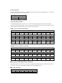
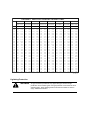
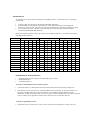
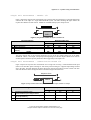
Maximum Track Lead Length Without an Island
The transmitter lead length for Unidirectional approach tracks without an island should be limited to the
values given in Table below as a function of frequency and approach length.
Track Connections
Track connections for the PMD-4/4R and for terminations may be of the plug type, providing the plugs are
clean and bright, and that the rail holes are freshly drilled to prevent oxidation before insertion of the plug
connector.
WARNING Connecting a dummy load across a unidirectional Approach Track
Circuit makes the approach appear to be bidirectional to the
PMD-4/4R. When a dummy load is connected across the track, set
the UNI/BI parameter for that approach to Bidirectional when the
limited predict mode is used. Failure to comply with this specification
may cause shorter or longer than requested warning times. Short
warning times could result in death or serious injury. Reference
SRAC2.
Track Bonds
The track must be bonded within the approach length of the PMD-4. All bonds should be less than 6 inches
long and attached by thermite weld. When the PMD-4/4R is terminated with a narrow band shunt, bonding
should be extended an additional 20% beyond the termination.
Terminating PMD-4/4R Approaches
All PMD-4/4R approaches must be terminated whether they are bidirectional, semi-bidirectional, or
unidirectional.
WARNING Termination shunts should be placed at a distance based on
maximum train speed and requested warning time, plus 4 seconds.
Failure to properly place termination shunts could result in short
warning times. Short warning times could result in death or serious
Reference SRAC2.
WARNING When computing maximum train speed values, both the maximum
timetable speed and locomotive over speed tolerances must be
considered. Failure to comply with this specification may cause
shorter than requested warning times. Short warning times could
result in death or serious injury. Reference SRAC2.
1.
When installing termination shunts, all approach distance measurements are made from the termination
shunt to the PMD-4/4R’s nearest set of track wire connections at the crossing.
2.
The termination shunt position should be determined by adding a minimum of 4 seconds to the desired
warning time at the maximum train speed for the location.
3.
Terminations may be hardwire, wideband, NBS (narrow band shunt), or FSS (Frequency Selectable
Shunts) depending on if other signals are used on the Track.
4.
Whenever possible, terminations should be physically located between the rails in order to minimize
lead length.
5.
Leads should be connected to the rails with plug connectors which are crimped correctly to the ends of
the termination leads.
6.
Excess lead wire should be removed before crimping the plug connector.
7.
Terminations, if other than the hardwire type, should be buried in the ballast to a depth of at least 6
inches to prevent physical damage.
8.
If desired, both the NBS (narrow band shunt) and wideband shunt units may be housed in the optional
Model 385A-3 Junction Box and buried in the ballast. Termination leads should not exceed 1-foot
when housed in the Junction Box.
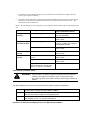
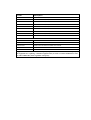
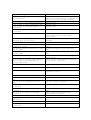
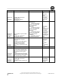
Refer to the following chart for selecting the type of termination shunt required with existing signals on the
rail.
Application
Existing Track Signals
Type of Termination Shunts
Non-Signal
Territory
No overlapping approaches
No. 9 AWG or larger stranded
track wire (hardwire)
When approaches overlap
NBS-1 or NBS-2 Narrow Band
Shunt or FSS
No overlapping approaches
1134D-2 Wideband Shunt or
1134D-3, 1134D-4, and 1134D-5
Dual Wideband shunts
When approaches overlap
NBS-1 or NBS-2 Narrow Band
Shunt or FSS
DC Coded Track
Circuits
all frequencies
NBS-1 or NBS-2 Narrow Band
Shunt or FSS
AC Coded Track
Circuits
Low current AC coded track
circuit
NBS-1 or NBS-2 Narrow Band
Shunt or FSS
High current AC coded track circuit
NBS-2 or NBS-3 Narrow Band
Shunt or FSS
High current AC coded track
circuit. Required for frequencies:
210, 211, 230, 267, and 285 Hz
NBS-3
Signal Territory DC Track Circuits
Narrow Band Termination Shunts
WARNING Using an NBS-1 or NBS-2 to bypass insulated joints may affect the
linearity of the approach resulting in short or long warning times.
Short warning times could result in death or serious injury. Reference
SRAC2.
The Narrow Band shunt comes in three types that are applied in different applications.
NBS-1
NBS-2
NBS-3
Low impedance shunt used where adjacent frequency separation is not critical.
Provides better shunting than either NBS-2 or NBS-3.
High impedance shunt used where several close frequencies are overlapping.
Provides less loading of adjacent crossings approaches.
Must be used in applications where high current AC coded cab signal is present.
Only available in 210, 211, 230, 267 and 285 Hz.
Guidelines for Selecting Overlapping Frequencies When Using the NBS-1
WARNING The Guidelines For Selecting Frequencies Used With An NBS-1 must
be strictly followed to prevent excessive loading of PMD-4/PMD-4R
approaches and short warning times. Short warning times could result
in death or serious injury. Reference SRAC2.
Guidelines for Selecting Overlapping Frequencies When Using the NBS-2
FSS (Frequency Selectable Shunts)
WARNING Inadvertent changes in frequency selection on a Frequency
Selectable Shunt (FSS) could negate broken rail detection or shorten
overlapping approaches. Follow the procedures for frequency
selection and remove all unused nuts from the FSS. Loss of broken
rail detection or shortened approaches could cause death or serious
injury. Reference SRAC2.
WARNING Incorrect frequency selection on a Frequency Selectable Shunt (FSS)
could negate broken rail detection or shorten overlapping approaches.
Access to the shunt must be restricted to authorized personnel, either
by burial in the track ballast, or by securing the shunt in a suitable
enclosure. Loss of broken rail detection or shortened approaches
could cause death or serious injury. Reference SRAC2.
FSS models FSS-1 and FSS-2 are frequency adjustable narrow band shunts used to terminate an approach of
a motion detector or constant warning system. The FSS is available in two configurations:
•
FSS-1 low impedance, similar to a NBS-1, minimum 5 ohm reactive inductance.
•
FSS-2 high impedance, similar to a NBS-2, minimum 10 ohm reactive inductance.
FSS units and the frequencies available for each model are listed in the following table.
FSS model
Frequency range
FSS-1A
86, 114, 151, 210, and 267 Hz
FSS-1B
267, 326, 392, 452, 522, and 560 Hz
FSS-1/2C
630, 686, 753, 816, 881, and 979 Hz
FSS-1D
86, 114, 156, 172, and 211 Hz
FSS-1E
211, 285, 348, 430, and 525 Hz
FSS-1/2F
430, 525, 645, 790, and 970 Hz
FSS-2A
86, 114, 151, 210, and 267 Hz
FSS-2B
267, 326, 392, 452, 522, and 560 Hz
FSS-2D
86, 114, 156, 172, and 211 Hz
FSS-2E
211, 285, 348, 430, and 525 Hz
May be
substituted for :
NBS-1
NBS-1 or NBS-2
NBS-1
NBS-1 or NBS-2
NBS-2
When applied to GETSGS crossing systems, FSS-1s and FSS-2s may be used anywhere an NBS-1 or
NBS- 2, respectively, would be applied.
WARNING Incorrect frequency selection on a Frequency Selectable Shunt (FSS)
could negate broken rail detection or shorten overlapping approaches.
Access to the shunt must be restricted to authorized personnel, either
by burial in the track ballast, or by securing the shunt in a suitable
enclosure. Loss of broken rail detection and shorten approaches
could cause death or serious injury. Reference SRAC2.
Setting the Operating Frequency
1. Remove the end cap from the FSS (Frequency Selectable Shunt).
2.
When using a dummy load to balance unequal approaches caused by un-bypassed insulated
joints, follow these additional steps:
•
Remove the link between the two terminals marked LOAD.
•
Connect the load coil between these two terminals.
3.
Remove all nuts from the frequency selection terminals.
4.
Install a gold nut on all appropriately marked frequency selection terminals. Install a clamp nut over
the gold nuts to secure them.
WARNING Inadvertent changes in frequency selection on a Frequency
Selectable Shunt (FSS) could negate broken rail detection or shorten
overlapping approaches. Follow the procedures for frequency
selection and remove all unused nuts from the FSS. Loss of broken
rail detection or shortened approaches could cause death or serious
injury. Reference SRAC2.
5.
Connect the two track leads across the rail.
6.
Replace the FSS end cap, and follow these additional steps:
•
•
Before tightening the end cap retaining nut, set the frequency marker to indicate the selected
frequency.
Torque the end cap retaining nut to a minimum of 10 to 12 foot-pounds.
7.
Secure the FSS by either burying the FSS in the track ballast or installing the FSS in a junction box or
inside track-side housing.
8.
Follow re-test procedures in Chapter 9 - Re-Test Guide of this manual to ensure proper crossing
warning system operation.
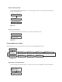
Wideband Termination Shunts
Wideband termination shunts are used in applications with steady DC track circuits with no overlapping
crossing approaches. Wideband shunt/Couplers are supplied in four different configurations (Figure X-X).
When using a wideband as a termination shunt the 1134D-2 single wideband will work or one of the dual
widebands can be used for redundancy. All models are designed for direct burial. Bury the wideband shunt in
the ballast between the rails. Excess wire length must be removed before crimping to plug connectors.
If desired, the Model 1134D-2 Single Wideband shunt/Coupler may be housed in a Model 385A-3 Junction Box
and buried in the ballast.
Bypassing Insulated Joints
WARNING Do not couple the set of insulated joints at the location where a PMD4/4R is connected in a unidirectional application. This set of insulated
joints makes the approach track circuit itself unidirectional. Coupling
this set of insulated joints would allow the track beyond the joints to
affect the impedance seen by the PMD-4/4R. The change in track
impedance could result in short or long warning times. Short warning
times could result in death or serious injury. Reference SRAC2.
WARNING Using an NBS-1 or NBS-2 to bypass insulated joints may affect the
linearity of the approach resulting in short or long warning times. Short
warning times could result in death or serious injury. Reference
SRAC2.
CAUTION
Do not couple insulated joints in high current AC applications as this
may cause erratic operation of the PMD-4/4R.
The PMD-4/4R must "see" the entire approach as continuous. If there are any insulated joints within the
approach, the PMD-4/4R requires joint couplers to bypass them.
The type of bypass selected depends upon the type of signal circuit in the approach. Two types of insulated
joint bypasses may be used:
1.
The Wideband Joint (or Shunt) Coupler.
2.
The TJC (Tunable Joint Coupler). When the PMD-4/4R is applied in limited predict mode, refer to
the "Minimum Distance to Joints When Coupled with TJCs" table on page X-X, for more
information.
Joint Couplers
Joint Couplers should be mounted near the insulated joint. Whenever possible, joint couplers should be
mounted within 3 feet of the insulated joints they are bypassing. However, when necessary, Tunable Joint
Couplers (TJCs) may be mounted away from the Track provided the following criteria are met:
1.
Connect all four TJC track wires to the rail. (Multiple TJCs at a set of insulated joints may be
connected to the rail through common track wires.)
2.
The maximum total TJC track wire length is 35 feet (11m).
3.
The additional track wire added to the TJC's normal 10-foot track wire length must be No. 6 AWG
minimum.
There is one potential side effect to adding additional track wire to TJCs. A decreasing Phase Fault
condition may occur on the approach of a train. If a decreasing Phase Fault condition occurs in relationship
to TJC replacement, the only solution is to reduce the track wire length by moving the TJCs nearer to the
track.
The types of mounting choices available depend on the type of joint coupler selected (TJC-1A or
wideband). The TJC-1A joint coupler may be housed in a Ballast Mount Hardware Kit or buried directly in
the ballast. The TJC-1A may also be mounted in the ballast between the ties and covered with a protective
steel plate bolted to the ties. The TJC-1A is supplied with dual parallel leads. Make sure that the leads
remain matched when connected to the rail to prevent shorting the joint. Excess wire length must be
removed before crimping the leads to plug connectors.
Wideband joint couplers are supplied in four different configurations. All models are designed for direct
burial. Bury the joint couplers in ballast between the rails or outside the Track within 3 feet of the joint.
Excess wire length must be removed before crimping to plug connectors.
If desired, the Model 1134D-2 Single Wideband Joint Coupler may be housed in a Model 385A-3 Junction
Box and buried in the ballast. The Wideband Shunt/Coupler Wiring Configurations are shown in Figure
X-X below.
Figure X-X
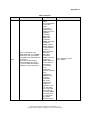
Joint Coupler Applications
Application
Non-Signal
Territory
Existing Track Signals
Type of Insulated
Joint Coupler
without audio frequency overlap
Does not apply
with audio frequency overlap
Does not apply
Signal
Territory - DC
Track
Circuits
DC track circuits on one or both sides of joints with
or without out audio frequency overlap
1134D-2 Single
Wideband or 1134D3/4/5 Dual Wideband
DC Coded
Track
all frequencies, but with DC coded track on one or
both sides of insulated joints.
TJC-1A
AC Coded
Track
Circuits
low current AC coded track circuit with AC coded
track on one or both sides to the joint
TJC-2/Cab
high current AC coded track circuit
Do not couple, use
unidirectional units to
remotely detect trains
Non-Coded DC Track Circuits
Insulated joints should be coupled with the Model 1134D-2 Single Wideband Joint Coupler in non-coded
DC track circuits.
Do not bypass more than:
Four sets of insulated joints per approach for frequencies of 86 Hz thru 135 Hz.
Five sets of insulated joints per approach for frequencies of 151 Hz and higher.
Use a Dual Wideband Joint Coupler when they are located:
o
In the first 50 percent of the approach from the crossing for PMD-4/4R frequencies 86 Hz through
135 Hz.
o
Within the first 1/3 of the approach from the crossing for PMD-4/4R frequencies 151 Hz through
392 Hz.
The Single Wideband Joint Coupler 1134D-2 is permissible on all frequencies when not in violation of the
above.
The Dual Wideband Joint Coupler is available in three versions. The only physical difference between
them is how the wires exit the coupler.
Coded DC, Coded AC, and Non-Coded AC Track Circuits
CAUTION
Do not couple insulated joints in high current AC applications as this
may cause erratic operation of the PMD-4/4R.
When bypassing insulated joints in low current AC applications, the TJC-2/CAB can be used if the
following requirements are met:
The PMD-4/4R can have a maximum of 2 sets of joints bypassed with TJCs within each approach of a
bidirectional application.
Unidirectional PMD-4/4R applications can have no more than 2 sets of joints bypassed with TJCs.
Limited Predict Mode
When the PMD-4/4R is used in limited predict mode, there is a minimum distance from the PMD-4/4R
track wires that joints can be bypassed with TJCs. Refer to the "Minimum Distance To Joints When
Coupled With TJCs" table on the next page for the minimum distances for each frequency.
The TJC-2/CAB may be buried or is available with tie mount hardware. The TJC-2/CAB can be installed
in DC Coded Track circuits where vibration is a problem.
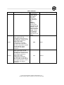
Tunable Joint Couplers
Coupler
Part Number
Track Circuit
Mounting
TJC-1A Tunable
Joint Coupler
250491-*
Coded-DC
Direct Burial
TJC-2A Tunable
Joint Coupler
300187-*
Coded-DC
Ballast Mount
TJC-3A Tunable
Joint Coupler
300188-*
Coded-DC
Tie Mount
(Low Vibration
Locations Only)
TJC-2/CAB
250376-*
Coded or Non-Coded AC
Direct Burial
TJC-2/CAB
300293-*
Coded or Non-Coded AC
Tie Mount
* = Add frequency from table “Minimum Distance to Joints When Coupled with TJCs”
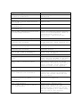
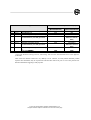
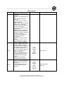
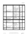
Minimum Distance to Joints When Coupled with TJCs (Limited predict Mode Only)
The following chart shows the minimum distance to couple with Tuned Joint Couplers when the PMD-4/4R is
applied in limited predict mode. When the PMD-4/4R is applied in motion detect mode only, TJCs can be
applied anywhere in the approach.
Frequency
1
Minimum Distance to First
Minimum Distance to Second
Set of Joints
Set of Joints
86 Hz
114 Hz
135 Hz
151 Hz
156 Hz
172 Hz
210 Hz
211 Hz
230 Hz
267 Hz
285 Hz
326 Hz
348 Hz
392 Hz
430 Hz
452 Hz
522 Hz
525 Hz
560 Hz
630 Hz
645 Hz
686 Hz
753 Hz
790 Hz
816 Hz
881 Hz
970 Hz
5500(1676)
3000 (914)
2215 (675)
2200 (671)
2190 (668)
2000 (610)
1650 (503
1650 (503)
1577 (481)
1300 (396)
1240 (378)
1100 (335)
1020 (311)
900 (274)
820 (250)
800 (244)
725 (221)
720 (219)
700 (213)
650 (198)
630 (192)
620 (189)
600 (183)
560 (171)
550 (168)
500 (152)
455 (139)
7500 (2286)
4300 (1311)
2927 (892)
3000 (914)
3010 (918)
2730 (832)
2200 (671)
2200 (671)
2123 (647)
1800 (549)
1700 (518)
1500 (457)
1420 (433)
1300 (396)
1230 (375)
1200 (366)
1100 (335)
1095 (334)
1060 (323)
1020 (311)
1010 (308)
1000 (305)
950 (290)
920 (280)
900 (274)
850 (259)
805 (248)
979 Hz
450 (137)
800 (244)
Distance applies to joints located on the same side of the crossing
2
Distance is measured in feet.
3
Distance in meters ( ).
Approach Frequency Selection
WARNING When an Approach Track Circuit Frequency Selection parameter is
changed, the PMD-4/4R defaults the associated Lumped
Impedance Adjustment, Transmitter Check Adjustment, Ballast
Compensation, Phase Compensation and Approach Transmitter Gain
parameters to their Non-Corrupt Default values. Failing to verify and
properly adjust all of these parameters before placing/returning the
PMD-4/4R into service could result in short or long warning times.
Short warning times could result in death or serious injury. Reference
SRAC2.
WARNING Incorrectly setting the Approach Track Frequency Selection
parameter could result in erratic operation of the crossing warning
system. Erratic Operation could result in short or long warning times.
Short warning times could result in death or serious injury. Reference
SRAC2.
The PMD-4/4R system allows the approach track transmitter/receiver frequency to be set, in the field, from
a list of standard frequencies.
If the Approach Track Circuit is set for Master Mode and the Approach Track Circuit frequency is set to a
frequency other than zero, the associated Approach Track Circuit transmitter and receiver will operate at
the selected frequency.
If the Approach Track Circuit is set for Slave Mode and the Approach Track Circuit frequency is set to a
frequency other than zero, the PMD-4/4R System will check to make sure the frequency present at the slave
input is equal to the frequency selected before allowing Approach Track Circuit transmitter and receiver
operation.
If the frequency selected is zero, the associated Approach Track Circuit transmitter and receiver will be
“disabled” and the associated “MDR” statuses will be set “False” (as if a train has been detected).
If the Approach Track Circuit Frequency is not fixed by the application, it may be changed in the field via
the display or Web GUI. Refer to the following tables to determine the frequencies for Bi-directional and
Uni-directional applications. See the Display Navigation section within this manual for details on this user
interface.
Frequency Selection Guidelines for Bi-directional Approaches
The following table is intended as a guideline to show the minimum and maximum approach lengths for a
Bi-directional PMD-4/4R with a ballast of 2 Ohms per 1,000 feet (305m) and up to 30 Ohms per 1,000
feet (305m) of Track. Distances are for one approach in a bidirectional application.
Frequency Selection Guidelines For Unidirectional Approaches
Refer to the following table for guidelines in determining the minimum and maximum approach length
distances that can be used in a unidirectional application with ballast of 2 Ohms per 1,000 feet and up to
30 Ohms per 1,000 feet of Track.
A PMD-4/4R used in a unidirectional application does not have as great an effective monitoring distance as a
PMD-4/4R used in a bi-directional application.
WARNING Connecting a dummy load across the Track makes a PMD-4/4R
(used in a unidirectional application) function as a bidirectional unit.
This requires making absolutely certain that when the PMD-4/4R is
used in the limited predict mode, that the “Uni/Bi” parameter is set to
"Bi" when a dummy load is used. The “Uni/Bi” parameter should be
set to "Uni" when no dummy load is used in a unidirectional
application. Failure to comply with this specification may cause
shorter or longer than requested warning times. Short warning times
could result in death or serious injury. Reference SRAC2.
When a unidirectional approach must be longer than specified in the next table, a dummy load can be
connected in series with the appropriate termination shunt and installed rail-to-rail at the insulated joints. If
this method is used, refer to the previous table for bidirectional approaches.
FREQUENCY SELECTION GUIDELINE UNI-DIRECTIONAL
2(l BALLAST
MAX TRACK
LENGTH IN FEET
40 BAlLAST
60 BALLAST
MAX TRACK
LENGTH IN FEET
MAX TRACK
LENGTH INFEET
80 BALLAST
MAX TRACK
LENGTH IN FEET
100 BALLAST
MAX TRACK
LENGTH INFEET
150 BALLAST
200 BALLAST
300 BALLAST
MAX TRACK
LENGTH INFEET
MAX TRACK
LENGTH INFEET
MAX TRACK
LENGTH INFEET
FREQ
MIN
MAX
MIN
MAX
MIN
MAX
MIN
MAX
MIN
MAX
MIN
MAX
MIN
MAX
MIN
MAX
86
114
135
151
156
720
615
584
560
550
535
485
485
470
440
425
400
380
360
340
330
315
315
305
290
290
275
265
260
255
250
240
240
3560
2840
2630
2470
2450
2300
2070
2070
2002
1870
1800
1670
1630
1530
1480
1430
1330
1330
1280
1200
1195
1170
1115
1090
1065
1035
970
965
720
615
584
560
550
535
485
485
470
440
425
400
380
360
340
330
315
315
305
290
290
275
265
260
255
250
240
240
5000
4000
3699
3470
3450
3300
2930
2930
2842
2670
2550
2370
2300
2170
2100
2030
1900
1900
1800
1700
1660
1630
1570
1510
1500
1465
1360
1365
720
615
584
560
550
535
485
485
470
440
425
400
380
360
340
330
315
315
305
290
290
275
265
260
255
250
240
240
6090
5180
4690
4410
4340
4130
3710
3640
3500
3220
3150
2940
2800
2660
2520
2450
2310
2240
2170
2100
2030
1960
1890
1820
1820
1750
1680
1680
720
615
584
560
550
535
485
485
470
440
425
400
380
360
340
330
315
315
305
290
290
275
265
260
255
250
240
240
7070
5950
5390
5110
4970
4760
4270
4270
4060
3710
3640
3360
3220
3080
2940
2800
2660
2590
2520
2380
2380
2310
2170
2100
2100
2030
1890
1890
720
615
584
560
550
535
485
485
470
440
425
400
380
360
340
330
315
315
305
290
290
275
265
260
255
250
240
240
7840
6650
6090
5670
5600
5320
4760
4760
4550
4200
4060
3780
3640
3430
3220
3150
2940
2940
2800
2660
2660
2520
2450
2380
2310
2240
2170
2100
720
615
584
560
550
535
485
485
470
440
425
400
380
360
340
330
315
315
305
290
290
275
265
260
255
250
240
240
9660
8190
7420
7000
6860
6510
5810
5810
5530
5110
4970
4620
4410
4200
3990
3850
3570
3570
3500
3290
3220
3150
3010
2940
2870
2730
2590
2590
720
615
584
560
550
535
485
485
470
440
425
400
380
360
340
330
315
315
305
290
290
275
265
260
255
250
240
240
11130
9450
8540
8050
7910
7490
6720
6720
6370
5880
5670
5320
5110
4830
4620
4480
4130
4130
3990
3780
3710
3640
3430
3360
3290
3150
3010
3010
720
615
584
560
550
535
485
485
470
440
425
400
380
360
340
330
315
315
305
290
290
275
265
260
255
250
240
240
13650
11550
10500
9870
9660
9170
8190
8190
7840
7210
7000
6510
6300
5880
5600
5460
5110
5040
4900
4620
4550
4410
4200
4130
4060
3850
3710
3640
172
210
211
230
267
285
326
348
392
430
452
522
525
560
630
645
686
753
790
816
881
970
979
323-00 7 b
Lightning Protection
WARNING Air gap arresters provide the only approved type of track surge
protection. Use of other types of surge protection could result in short
warning times. Short warning times could result in death or serious
injury. Reference SRAC2.
Chassis
GE Transportation Systems Global Signaling recommends grounding the PMD-4/4R chassis to ensure
compliance with FCC requirements.
Supply Battery
The PMD-4/4R system battery can be protected from lightning in 1 of 3 ways:
1.
Using an MDSA panel (for system battery current of 0A-6A), or
2.
Using an MDSA-1XS/-2XS panel (for system battery current of 0A-12A), or
3.
By using discrete air gap arrestors and equalizers.
Note: If using discrete arrestors, connect them according to Figure X-X below with addition of
an external 20A slo-blo fuse between the battery and arrestors.
4.
Protect the supply battery by installing an equalizer between positive and negative battery.
5.
Install an air-gap arrestor from positive and negative battery to earth ground. The schematic diagram
is shown in Figure X-X below.
Figure X-X
Crossing Track Circuits Surge Protection
WARNING Air gap arresters provide the only approved type of track surge
protection. Use of other types of surge protection could result in short
warning times. Short warning times could result in death or serious
injury.
Follow guidelines in this manual for wiring requirements to determine appropriate wire size. In most
installations, B12, N12, and the TX +/- and RX +/- terminals are the only ones that need external surge
protection. The MDSA provides suitable surge protection.
The MDSA-1/-1XS is configured to provide all the battery and track wire surge protection for PMD-4/4R
crossing units. The MDSA wiring connections are shown in Figure X-X below.
Figure X-X
Vital Inputs and Outputs Surge Protection
CAUTION
Inputs and outputs that leave the signal case must be protected from
lightning and surges by installing lightning arresters. All spare
conductors in the cable must also be protected in the same fashion.
Any wires that go outside the signal cases are susceptible to electrical surges and must be protected with an
air-gap arrester to earth ground. The Lightning Arrester Schematic for Vital Input or Output is shown in
Figure X-X below.
Figure X-X
Interconnect Panels
Interconnect panels can be used when retrofitting a crossing house that has legacy crossing control
equipment. The interconnect panels are designed to minimize wiring changes with terminal layouts similar
to the equipment that is being replaced. Wires can be transferred from the existing equipment terminal to
the interconnect panel terminal one at a time for minimal wiring errors. A pre-wired cable will connect the
panel to the PMD-4/4R Wago connector. The Interconnect panel are available to replace the PMD-1/1B,
PMD-2, PMD-3/3R and HXP-1/1B/1C/2.
Insert drawings of the different panels with wiring diagrams
Peripheral Equipment
Part No.
Description
250016-001
1133A-2 60Hz Shunt
250016-002
1133A-2 180Hz Shunt
250249-XXX
*NBS-1 Narrow Band Shunt used with terminal housing (1ft. leads)
250250-XXX
*NBS-1 Narrow Band Shunt with 10ft. leads
250516-XXX
*NBS-2 Narrow Band Shunt used with terminal housing (1ft. leads)
250568-XXX
*NBS-2 Narrow Band Shunt with 10ft. leads
250896-J03
*NBS-3 Narrow Band Shunt with 10ft. leads (for 267 Hz applications in
high current Cab only)
250141-001
5025A Track Battery Reactor
250158-1A
1180B Battery Reactor
225238-001
385A-3 Terminal Housing Pipe & Mounting Foot 20"
225238-003
385A-3 Terminal Housing Pipe & Mounting Foot 24"
250069-001
1186A-1 Dummy Load 1000 ft (305m).
250069-002
1186A-2 Dummy Load 2000 ft (610m).
250204-001C
MDSA-1 Motion Detector Surge Arrester (for one track) (0A-6A)
250675-000
MDSA-2 Motion Detector Surge Arrester (for two tracks) (0A-6A)
250204-100
MDSA-1XS Motion Detector Surge Arrester (for one track) (0A-12A)
250675-100
MDSA-2XS Motion Detector Surge Arrester (for two tracks) (0A-12A)
Frequency Selectable Shunts
250849-000
FSS-1A, Frequency range (86Hz - 267Hz)
250849-001
FSS-1B, Frequency range (267Hz - 560Hz)
250849-002
FSS-1/2C, Frequency range (630Hz - 979Hz)
250849-003
FSS-1D, Frequency range (86Hz - 211Hz)
250849-004
FSS-1E, Frequency range (211Hz - 525Hz)
250849-005
FSS-1/2F, Frequency range (430Hz - 970Hz)
250850-000
FSS-2A, Frequency range (86Hz - 267Hz)
250850-001
FSS-2B, Frequency range (267Hz - 560Hz)
250850-002
FSS-2D, Frequency range (86Hz - 211Hz)
250850-003
FSS-2E, Frequency range (211Hz - 525Hz)
FSS Dummy Loads
227032-000
FSS Load 250 ft (76m).
227032-001
FSS Load 500 ft (152m).
227032-002
FSS Load 750 ft (229m).
227032-003
FSS Load 1000 ft (305m).
227032-004
FSS Load 1250 ft (381m).
227032-005
FSS Load 1500 ft (457m).
227032-006
FSS Load 1750 ft (533m).
Part No.
Description
227032-007
FSS Load 2000 ft (610m).
227032-008
FSS Load 2250 ft (686m).
227032-009
FSS Load 2500 ft (762m).
227032-010
FSS Load 2750 ft (838m).
227032-011
FSS Load 3000 ft (914m).
227032-012
FSS Load 3250 ft (991m).
227032-013
FSS Load 3500 ft (1067m).
227032-014
FSS Load 3750 ft (1143m).
227032-015
FSS Load 4000 ft (1219m).
Interconnect Panels
1000702-000
PMD-4/4R GENERIC INTERFACE PANEL
1000702-002
PMD-2 TO PMD-4 INTERFACE PANEL
1000702-003
PMD-3/3R TO PMD-4 INTERFACE PANEL
1000702-004
HXP-1/1B/1C/2 TO PMD-4 INTERFACE PANEL
1000702-005
PMD-1/1B TO PMD-4 INTERFACE PANEL
Equipment marked with an asterisk is frequency dependent. It must be of the same frequency as
the equipment it is replacing. Unmarked equipment may be used as common maintenance stock
for other PMD-4/4R systems regardless of frequency.
Chapter 3 – Setup, Calibration, and Checkout using the Display and
Keypad
Contents
Introduction........................................................................................................................................... X-X
Application Program ............................................................................................................................. X-X
Input and Output descriptions for the standard application programs............................................... X-X
pmd-4_md and pmd-4r_md............................................................................................................. X-X
pmd-4_cw and pmd-4r_cw .............................................................................................................. X-X
Local User Confirmation ....................................................................................................................... X-X
Home Menu ........................................................................................................................................... X-X
System Configuration ........................................................................................................................... X-X
Application Selection ..................................................................................................................... X-X
Application Information .................................................................................................................. X-X
Setting the Date & Time ................................................................................................................. X-X
Ethernet Configuration ................................................................................................................... X-X
Vital Configuration ......................................................................................................................... X-X
Log Management ........................................................................................................................... X-X
Alarms ........................................................................................................................................... X-X
Executive Information .................................................................................................................... X-X
Software Activation ........................................................................................................................ X-X
PMD-4 Chassis ID/SSM Mismatch Menu ........................................................................................ X-X
Set Chassis ID Menu ...................................................................................................................... X-X
Crossing Setup Menu ........................................................................................................................... X-X
Approach Setup .................................................................................................................................... X-X
Frequency ...................................................................................................................................... X-X
Master/Slave setting ....................................................................................................................... X-X
Approach Calibration ...................................................................................................................... X-X
Direction Mode (Uni/Bi) .................................................................................................................. X-X
Approach Length ............................................................................................................................ X-X
Transmitter Check .......................................................................................................................... X-X
Field Adjusting Tuned Joint Couplers.............................................................................................. X-X
LOS Time ....................................................................................................................................... X-X
False Shunt .................................................................................................................................... X-X
Approach Release .......................................................................................................................... X-X
Auto RX ......................................................................................................................................... X-X
Island Setup .......................................................................................................................................... X-X
Internal Island ................................................................................................................................. X-X
Island Frequency .................................................................................................................... X-X
Island LOS .............................................................................................................................. X-X
Island Fault Delay ................................................................................................................... X-X
Island Calibration .................................................................................................................... X-X
External Island................................................................................................................................ X-X
Enabling/Disabling Islands .............................................................................................................. X-X
Limited Prediction................................................................................................................................. X-X
Lumped Impedance Adjustment ...................................................................................................... X-X
MDR1 Warning Time Adjustment .................................................................................................... X-X
MDR1 AP Time ....................................................................................................................... X-X
MDR2 Warning Time Adjustment .................................................................................................... X-X
Final Checkout (Initial Installation) ....................................................................................................... X-X
Checkout (Existing Installations) ......................................................................................................... X-X
Maintenance Procedures ...................................................................................................................... X-X
Fusing ............................................................................................................................................ X-X
SSM Module .................................................................................................................................. X-X
Chapter 3 – PMD-4/4R Setup, Calibration, and Checkout
WARNING After initial setup and adjustment of PMD-4/4R parameter settings,
adequate testing must be performed to detect any errors related to
these configuration settings. The tests should be performed before
the unit is placed into service and in accordance with standard
railroad, FRA, and/or other regulatory agency rules. The tests should
be performed by qualified personnel that have the knowledge to
correctly and safely discharge the tests. Failure to adequately test the
PMD-4/4R unit after the initial setup could result in death or serious
injury. Reference SRAC2.
WARNING Railroad Configuration Management Procedures must ensure that all
PMD-4/4R units are configured with the proper revisions of modules
and firmware (both application and executive) and that updates are
completed in a timely manner when made available by GE
Transportation Systems Global Signaling. Operating with incorrect
firmware may result in death or serious injury. Timely is defined as
without undue delay per 49 CFR 236.1023(j). Reference SRAC2.
WARNING Railroad Configuration Management Procedures must ensure that the
proper values are set for each crossing parameter, vital timer, vital
configuration setting (vital soft switches), PTC Wireless Crossings
vital parameters and vital remote parameter in their PMD-4/4R units.
Incorrect settings may result in death or serious injury. Reference
SRAC2.
WARNING Incorrect adjustment of RX could result in short, long, or continuous
warning times. Short warning times could result in death or serious
injury. Reference SRAC2.
WARNING Incorrect placement of shunts during Island calibration could result in
no warning while a train is occupying the island. Failing to detect
trains in the island could result in death or serious injury. Reference
SRAC2.
Introduction
This section provides the maintainer with a step-by-step process for setup and adjustment of new or relocated
PMD-4/4R equipment. The display menus for making adjustments are shown in this chapter. The same
parameters may be set or adjusted using the Web GUI (see chapter X). This section addresses setup of the
standard application programs shipped with the unit.
Application Programs
The PMD-4/4R is shipped from the factory with a standard application set. Each application will have a different
chassis ID. There will be two applications pre-loaded onto the memory module connected on the side of the unit for
each cabinet type. Refer to the following table for a list of the applications available for each cabinet type with a brief
description.
PMD-4/4R Applications
Cabinet
Type
Application
Name
Chassis
ID
pmd-4_md
1
pmd-4_cw
2
pmd-4r_md
3
pmd-4r_cw
4
PMD-4
PMD-4R
Description
Motion detector application for the non-redundant PMD-4 system.
This application is capable of limited prediction when the optional
selective function key is enabled.
Limited predictor application with advanced traffic preemption
output for the non-redundant PMD-4 system. Requires the optional
selective function key to enable the predict feature
Motion detector application for the redundant PMD-4R system. This
application is capable of limited prediction when the optional
selective function key is enabled.
Limited predictor application with advanced traffic preemption
output for the redundant PMD-4R system. Requires the optional
selective function key to enable the predict feature
Input and Output descriptions for the standard application programs
The inputs and outputs on the standard application programs will vary depending on which program is selected. The
following tables describe the functions of the inputs and outputs of each application program.
Application programs “pmd-4_md” and “pmd-4r_md” Input/output descriptions
ISLI
RSOI
AUXI1
AUXI2
INPUT Descriptions
The ISLI input that controls the island assignment in logic when the External island is selected. This
input should be tied high to battery in remote applications. When applied back to back with a unit that
encompasses the island, the ISLI input will be supplied by the island output from the PMD-4 with the
island. This input is not used when the Internal Island is selected.
The RSOI input controls the reverse switch override logic. When the RSOI is de-energized MDR1
(MDR output) will react immediately to a sudden shunt in the approach. When the RSOI is energized
the sudden shunt override is in place to override a sudden shunt (trailing switch in the approach) for 4
seconds before reacting to motion.
The AUXI1input provides positive control over MDR1 ( MDR output). When de-energized the MDR
output will be de-energized. When energized the MDR output will be energized if not in detection.
The AUXI2 input is not used in logic but is a recorded variable that can be used as a recorder input for a
GD, GP or POR input for logging purposes.
OUTPUT Descriptions
MDR
The MDR output is the output for MDR1. This output is the motion detector output to start the crossing
activation sequence. This output can be used to drive a crossing control relay or AUX Input on another
unit. The MDR output can also be connected directly to a solid state crossing controller input.
ISLO
The ISLO output indicates the status of the island circuit when the internal island is selected. When the
external island is selected the ISLO output will follow the ISLI input.
The AXO1 output is used to indicate module health. This output is normally energized and will be deenergized when any internal module health statuses goes false.
AXO1
AXO2
Note: This output will also be false if the VIO Input or output redundancy is compromised in the pmd4r_md application.
The AXO2 output is used to indicate when an approach or island is disabled. This output is normally
energized and will be de-energized if an approach or island is disabled.
Application programs “pmd-4_cw” and “pmd-4r_cw” Input/output descriptions
ISLI
RSOI
AUXI1
AUXI2
MDR
ISLO
AXO1
AXO2
INPUT Descriptions
The ISLI input that controls the island assignment in logic when the External island is selected. This
input should be tied high to battery in remote applications. When applied back to back with a unit that
encompasses the island, the ISLI input will be supplied by the island output from the PMD-4 with the
island. This input is not used when the Internal Island is selected.
The RSOI input controls the reverse switch override logic. When the RSOI is de-energized MDR2
(AXO1 output) will react immediately to a sudden shunt in the approach. When the RSOI is energized
the sudden shunt override is in place to override a sudden shunt (trailing switch in the approach) for 4
seconds before reacting to motion.
The AUXI1input provides positive control over MDR1 ( MDR output). When de-energized the MDR
output will be de-energized. When energized the MDR output will be energized if not in detection.
The AUXI2input provides positive control over MDR2 (AXO1 output). When de-energized the AXO1
output will be de-energized. When energized the AXO1 output will be energized if not in detection.
OUTPUT Descriptions
The MDR output is the output for MDR1. This output is the motion detector output to start the crossing
activation sequence. This output can be used to drive a crossing control relay or AUX Input on another
unit. The MDR output can also be connected directly to a solid state crossing controller input.
The ISLO output indicates the status of the island circuit when the internal island is selected. When the
external island is selected the ISLO output will follow the ISLI input.
The AXO1 output is the output for MDR2. MDR2 is the advanced preemption MDR paired with
MDR1 as a preempt pair. AXO1 will control the advanced traffic preempt relay used to start the
advanced traffic preempt cycle.
The AXO2 output is used to indicate when an approach or island is disabled. The AXO2 output is also
used to indicate module health. This output is normally energized and will be de-energized if an
approach or island is disabled or any of the internal module health statuses goes false.
Note: This output will also be false if the VIO Input or output redundancy is compromised in the pmd4r_cw application.
Local User Confirmation
A number of PMD-4/4R setup parameters are vital (safety critical). One mechanism utilized to secure these
parameters is referred to as Local User Confirmation. The Local User Confirmation ensures that an actual
user is physically present at the PMD-4/4R before an application program can be selected or any PMD-4/4R
crossing setup parameter can be modified using the front panel display. Before a vital adjustment can be made,
a three digit number will be displayed on the LCD display that needs to be entered om the keypad to confirm a
local user. Local User Confirmation is canceled in two ways. First, it will automatically cancel, thirty minutes
after the last keystroke on the keypad. Second, if Local Presence is granted using the Web GUI, and Local User
Confirmation through the keypad is currently active, the Local User Confirmation is cancelled and Local
Presence on the WebGUI is active. In the following figure X-X below, is a five digit confirmation code. To
confirm, enter the number listed in the confirmation message and press the Enter button.
Local User Confirm
Local User Confirm
Confirm 16845>
Figure X-X
Home Menu
The PMD-4/4R Home menu is shown in Figure X-X below.
Home Menu
Crossing Setup
System Configuration
Crossing
Maintenance
Figure X-X
System Configuration Menu
The System Configuration Menu is used to setup the following configuration options.
•
•
•
•
•
•
•
•
Select the Application
View Application Information
View executive Information
Set the date & Time
Configure the Ethernet ports
View and Change Vital Configuration software Switches
View and Clear Alarms
Activate Executive Version
The System configuration menu map is shown in Figure X-X below.
System Configuration
Application
Selection
Set Chassis ID
Vital Configuration
Ethernet Config
Chassis/SSM Mismatch
Local User Confirm
Log Management
Alarms
Application Info
Set Date/Time
Software Activation
Executive Info
Figure X-X
Application Selection
The PMD-4/4R can store multiple, independent, application programs on the memory module. The user must
select the exact application program for a particular location. Application Program selection information is
stored on the PMD-4/4R SSM.
PMD-4/4R application programs can be selected via the front panel display or Web GUI in the system
configuration menu.
Selecting the Application Using the Front Panel Display on initial installation
WARNING When entering information on the display that requires confirmation,
verify that the new value re-displayed by the system matches the
intended value. Confirmation of an incorrect value could result in a
less restrictive condition which could cause death or serious injury.
Reference SRAC2.
The PMD-4/4R Application Selection Menu is shown in Figure X-X below.
APPLICATION
SELECTION
Vital App CRC#FAFA
001 VAppName1*
001
↑↓>
Vital App
VappName1
002
↑↓>
Vital App
VappName2
003
↑↓>
Vital App
VappName3
003
↑↓>
Vital App
VappName3
Cancel
Repeat up/down arrow until
desired application is displayed
Enter
Cancel
Cancel
000
↑↓>
Non-Vital App
NVDefault App
Non-Vital application selection begins
with currently loaded NV application
001
↑↓>
Non-Vital App
NVAppName1
Repeat up/down arrow until
desired application is displayed
001
NVAppName1
Enter/YES Cancel/NO
Vital ParamsDefault
Enter/YES Cancel/NO
Application Selected
System Resetting
Figure X-X
Application Information
This menu appears if a different vital
application was selected. Otherwise it is
skipped
Each application program will have a unique checksum and CRC. Verify that the checksum and CRC match the
application circuit plans. The Application Information Menu is shown in Figure X-X below.
APPLICATION INFO
EPT CRC = 2A16
CHECKSUM = 2E1D
ACE EDITOR 5.6.**
<>1 or 3 to scroll
Figure X-X
Setting the Date & Time
The Date and Time are used to stamp events in the various PMD-4/4R logs. To set the PMD-4/4R Date and Time
use the Date and Time Menu shown in Figure X-X below.
Date/Time
DST Option only available when the Time Sync is set to other than None
Date/Time*
Time= HH:MM:SS
Date/Time*
Date=MM-DD-YY
Date/Time*
Time Zone= 6
Time=HH:MM:SS
Set HHMMSS>
Date=MM-DD-YY
Set MMDDYY>
Time Zone= 6
↑↓To Change> 5
Date/Time
Config Daylit Saving
Date/Time *
Request Time Update
Request Time Update
Enter/YES Cancel/NO
Config DST*
DST End= mo:MM wk:W
Config DST*
DSR = Enabled
Config DST*
DST Str=mo:MM wkW
DST End= mo:MM wk:W
↑↓To Change>
DST Enable=Disable
↑↓To Change>Enable
DST Strt= mo:MM wk:W
↑↓To Change>
DST End=mo:MMwk:W
Enter/YES Cancel/NO
DST Enable=Enable
Enter/YES Cancel/NO
DST Strt=mo:MMwk:W
Enter/YES Cancel/NO
Date/Time *
Sync= None
Sync= None
↑↓To Change> None
Code Line
Vital Remote
EMP
SNTP
Sync= Code Line
Enter/YES Cancel/NO
Figure X-X,
The Date/Time Menu allows access to menus for display and modification date and time options.
Time
The Time Menu provides the ability to display and set the current time.
Date
The Date Menu provides the ability to display and set the current date.
Time Zone
The Time Zone Menu provides the ability to display and set the local time zone reference used for adjusting
incoming time references contained in Greenwich Mean Time (GMT) based ATCS time messages. Time zone
5 represents Eastern Standard Time (EST) and 8 represents Pacific Standard Time (PST)
Ethernet Configuration
The PMD-4/4R has two Ethernet ports available for setup and diagnostics. To change the Ethernet port settings
using the keypad and display. The Ethernet Configuration menu is shown in Figure X-X below.
Figure X-X
Ethernet port configuration involves setting the following parameters:
•
•
•
•
•
•
•
•
•
•
•
IP Address for Ethernet 1 and Ethernet 2
Subnet Mask settings for Ethernet 1 and Ethernet 2
Default Gateway address
HTTP TCP Port Number for Web GUI access
Trusted Sources Enabled / Disabled
Trusted Source parameters (Trusted IP Network Address / Netmask)
Telnet Enable/Disable
Telnet Username and Password
Telnet Port Number
Telnet Trusted Source Parameters (Enable, Trusted IP Network Address / Netmask)
Routing Table Entries
•
Web GUI Inactivity Time-out
Parameter
Ethernet 1 IP Address:
Ethernet 1 Subnet Mask:
Ethernet 1 DHCP Server
Ethernet 1 DHCP Server IP Pool Start
Ethernet 1 DHCP Server IP Pool End
Ethernet 1 DHCP Server Default Gateway
Ethernet 2 IP Address:
Ethernet 2 Subnet Mask:
Ethernet 2 DHCP Server
Ethernet 2 DHCP Server IP Pool Start
Ethernet 2 DHCP Server IP Pool End
Ethernet 2 DHCP Server Default Gateway
Default Gateway:
Trusted Source / Network 1
Trusted Source / Network 2
Telnet Port 1
Telnet Port 2
Telnet Username
Factory Default
192.168.0.11
255.255.255.0
Enabled
192.168.0.12
192.168.0.44
192.168.0.11
192.168.1.12
255.255.255.0
Enabled
192.168.1.13
192.168.1.45
192.168.1.12
0.0.0.0 (No Default Gateway)
Disabled, IP = 0.0.0.0, Netmask = 0.0.0.0
Disabled, IP = 0.0.0.0, Netmask = 0.0.0.0
Disabled
Disabled
admin
Telnet Password
telnet
Telnet TCP Port
Telnet Trusted Source 1
Telnet Trusted Source 2
Routing Table Entries
23
Disabled, IP=0.0.0.0, Netmask=0.0.0.0
Disabled, IP=0.0.0.0, Netmask=0.0.0.0
No Route Entries
Web GUI Inactivity Time-out
60 minutes
Set Via
CDU
GUI
Vital Configuration (Vital Soft Switches)
There are a total of 32 vital configuration switches that can be configured for application specific operations. Refer to
the setup plans for your application before setting these switches. If no Vital Configuration Switches are defined in
the Application, this menu will not be shown. Note: The standard PMD-4/4R applications shipped with the unit do
not use vital configuration switches. Use the vital configuration menu to set the vital configuration switches. The
Vital Configuration menu is shown in Figure X-X below.
VITAL CONFIGURATION
View Configuration
Enter Configuration
View Configuration
VCS1
= TRUE
Enter Configuration
VCS1
= TRUE*
VCS1
= TRUE
↑↓to Change> TRUE
Verified Entry
Figure X-X
Log Management Menu
Use the Log Management menu to view and configure the logs. The log management menu is shown in Figure X-X
below.
Log Management
Error Log
Train Record Log
Figure X-X
Error Log Menu
The Error Log menu is shown in Figure X-X below.
Error Log
View Error Logs
Logs = 35
0001 04-16 15:56:38
ATC High Signal
B:APCF 01370
High Signal Fault
Erase Error Logs
Logs = 35*
0004 04-14 13:20:25
User
App Chg:
VApp
0003
04-14
14:10:30
User
App Chg:
VApp
0002
04-15
06:00:20
User App Chg: VApp
Error Logs = 35
Press ENTER to Erase
Note: Bottom line scrolls through entire
message at a rate of 3 characters per second.
Figure X-X
Train Record Log Menu
The Train Record Log menu is shown in Figure X-X below.
Train record Log
For maintenance only
Not used in WT Calc
View Train Rec Logs
Logs = 51
0001 04-16 15:56:38
T1 M1 WT=35 Mode=MD
Erase train Rec Logs
Logs = 51*
0004 04-15 12:20:25
T1 M1
WT=40
Mode=MD
0003
04-16
13:10:20
T1 M1
WT=37
Mode=MD
0002
04-15
06:00:20
T1 M1 WT=35 Mode=AUX
Error Logs = 51
Press ENTER to Erase
Figure X-X
Alarms
The System Alarms Menu provides the ability to view and clear system alarms. The Alarms menu is shown in Figure
X-X below.
Alarms
Alarm #1 (of 2) *
Open/Broken Rail
Alarm #2 (of 2) *
Battery Low
Battery Low
Press ENTER to erase
Figure X-X
Executive Information
The executive version and XTI DSP version can be viewed on the display. The Executive Information menu is
shown in Figure X-X below.
Executive
Information
VPM-A Processor
VPM-B Processor
VPM-C Processor
Data window
Data window
Data window
XTI DSP-AB Processor
XTI S1
A:00344fa9
DSP CRCS B:3b2a4778
All data windows like
this
PN: <xxxxxx-xxx> Ver
← → 1 or 3 to scroll
The first line contains scrollable
executive information
Figure X-X
Software Activation
The Software Activation menu allows a Maintainer to activate an Executive file that has been uploaded to the
system. The Software Activation option must be used to enable the use of the new version of the Executive on the
system. The Software Activation menu only appears when there is a file of that type that is available to activate. The
Software Activation menu is shown in Figure X-X below.
Software Activation
Executive*
Activate Executive
Enter/YES Cancel/NO
Figure X-X
PMD-4 Chassis ID/SSM Mismatch Menu
The Chassis ID/SSM Mismatch menu is shown in Figure X-X below.
Chassis ID/SSM *
Mismatch
Replaced =Chassis ID
↑↓ To Change> SSM
Replaced = SSM
Enter/YES Cancel/NO
Figure X-X
Set Chassis ID Menu
The Chassis ID menu can be used to view or modify the chassis ID. The Chassis ID can be set to an 8 bit value from
0-254. The Chassis ID menu is shown in Figure X-X below.
Set Chassis ID *
Chassis ID = 0
Chassis ID
↑↓ To Change>
=0
5
Chassis ID
5
Enter/YES Cancel/NO
Figure X-X
Crossing Setup Menu
Setting up the PMD-4/4R using keypad and display will be accomplished in the Crossing Setup Menu. The
Crossing Setup menu is shown in Figure X-X below.
Crossing Setup
Frequency
FREQ=
Master/Slave
TKMS=
Master*
RX Adjust
Approach Length
APLEN=
1000 ft*
Direction Mode
DIR=
Bi*
Limited Predict
Select Island Type
Type = External*
Auto RX = Enabled*
LOS Time
LOS= 16s*
False Shunt
Disabled
Approach Release
Disabled
TCA
TCA=0*
267HZ*
TCI=0.5
Figure X-X
Setting Crossing Parameters in the Field
All crossing parameters that are not fixed by the application program can be modified via the PMD-4/4R
keypad and display or Web GUI. The value of the parameters changed via the keypad or Web GUI are stored in
non-volatile memory on the PMD-4/4R memory module.
When an application program is selected and loaded, the vital crossing parameters are set to the default values
defined in the application. Use program information listed on the circuit plans for the values to be used for the
unit setup.
Note:
One exception to this rule is Site ID. The PMD-4/4R Site ID can only be set via the Web GUI.
Approach Setup
WARNING Incorrectly setting any of the Approach Track Circuit parameters could
result in a shorter or longer than desired warning time. Short warning
times could result in death or serious injury. Reference SRAC2.
Refer to circuit plans or fill out a Grade Crossing Location Record to record all setup parameters for the
location and keep these records with the PMD-4/4R unit. Following are the setup parameters for the PMD4/4R
•
•
•
•
•
•
•
•
•
•
•
•
Approach Track Frequency
Approach Track Master/Slave
Approach Track RX
Approach Direction Mode
Approach Length
Transmitter Check Adjustment
LOS (Loss of Shunt Time)
False Shunt Detect Enable/Disable
Approach Release Detect Enable/Disable
Auto RX Enable/Disable
Island Type
Limited Predict
Approach Frequency Selection
WARNING When an Approach Track Circuit Frequency Selection parameter is
changed, the PMD-4/4R defaults the associated Lumped Impedance
Adjustment, Transmitter Check Adjustment, Ballast Compensation,
Phase Compensation and Approach Transmitter Gain parameters to
their Non-Corrupt Default values. Failing to verify and properly adjust
all of these parameters before placing/returning the PMD-4/4R into
service could result in short or long warning times. Short warning
times could result in death or serious injury. Reference SRAC2.
WARNING Incorrectly setting the Approach Track Frequency Selection
parameter could result in erratic operation of the crossing warning
system. Erratic Operation could result in short or long warning times.
Short warning times could result in death or serious injury. Reference
SRAC2.
The PMD-4/4R system allows the approach track transmitter/receiver frequency to be set, in the field, to any
one of a predefined list of frequencies. The frequency can be changed in the field via the keypad. The
Frequency menu is shown in Figure X-X below.
Frequency
FREQ=
267HZ*
Frequency = 267Hz*
↑↓ To Change> 326HZ
Freq=326HZ RECAL REQ
Enter/YES Cancel/NO
Figure X-X
Operating Frequencies
86 Hz
172 Hz
285 Hz
452 Hz
645 Hz
881 Hz
114 Hz
210 Hz
326 Hz
522 Hz
686 Hz
970 Hz
135 Hz
211 Hz
348 Hz
525 Hz
753 Hz
979 Hz
151 Hz
230 Hz
392 Hz
560 Hz
790 Hz
156 Hz
267 Hz
430 Hz
630 Hz
816 Hz
Setting the Master/Slave Parameter
The Master/Slave Parameter is set for each individual approach track to synchronize approach frequencies. The
PMD-4/4R can be synchronized with an XP4 or HXP-3. Master/Slave Synchronization is accomplished by
connecting the MS + and MS- on the J3 connectors on one PMD-4/4R to the MS + and MS- J3 connectors to
another PMD-4/4R, XP4 or HXP/PMD-3 with the same polarity meaning Unit1(M+) should connect to
Unit2(M+) and so forth with the (M- )connections. Set one unit to “Master” with all other units connected by the
MS+ and MS- terminals set to “Slave”. Up to 11 Slave units can be attached to one Master. This parameter may be
changed in the field via the front panel display. The Master/Slave menu is shown in Figure X-X below.
Master/Slave
TKMS=
Master*
TKMS = Master
↑↓ To Change> Slave
TKMS=
Enter/YES
Slave
Cancel/NO
Figure X-X
Approach Calibration
WARNING Incorrect adjustment of RX could result in short, long, or continuous
warning times. Short warning times could result in death or serious
injury. Reference SRAC2.
Approach Calibration
To calibrate the approach RX, select the RX Adjust menu to auto calibrate the unoccupied approach. Select the
desired target RX (the target RX should nearly always be left set to 100), and the PMD-4/4R automatically
adjusts the approach transmitter gain and the associated Normal/Short/Very Short parameter to produce the
target RX. The user then acknowledges the successful calibration and the PMD-4/4R displays the new
proposed transmitter gain value and resulting RX. The user then confirms the new values and calibration is
complete for the approach track. The RX Adjust menu is shown in Figure X-X below.
RX Adjust
Auto Calibrate
Enter to begin>
Target RX = 100
↑↓ To Change> 100
Calibrating....\
Gain 128 Phase 53
XMGN=156 RX=100
Enter/YES Cancel/NO
<<Calibration Good>>
Enter/YES Cancel/NO
Figure X-X
WARNING Incorrectly setting the UNI/BI parameter for an approach track circuit
could result in short or longer than desired warning times. Short
warning times could result in death or serious injury. Reference
SRAC2.
WARNING Connecting a dummy load across a unidirectional Approach Track
Circuit makes the approach appear to be bidirectional to the PMD4/4R. When a dummy load is connected across the track, set the
UNI/BI parameter for that approach to Bidirectional. Failure to comply
with this specification may cause shorter or longer than requested
warning times. Short warning times could result in death or serious
injury. Reference SRAC2.
Depending on the application, the PMD-4/4R may need an approach track circuit that looks both directions out
from the crossing (bi-directional) or one that looks only one direction away from a set of insulated joints. The
PMD-4/4R allows the approach track to be set for either unidirectional or bi-directional operation. The
Directional Mode may be changed in the field via the display and keypad. The Direction Mode menu is shown
in Figure X-X below.
Direction Mode
DIR=
Bi*
DIR=
↑↓ To Change>
DIR=
Enter/YES
Bi
Uni
Uni
Cancel/NO
Figure X-X
Setting Approach Length
WARNING Incorrectly setting the Approach Length parameter for an approach
track circuit could result in short or longer than desired warning times.
Short warning times could result in death or serious injury. Reference
SRAC2.
WARNING Approach length must be measured from the track wire connections
on the termination side of the crossing island. Measuring from the
center of the crossing may result in short warning times. Short
warning times could result in death or serious injury. Reference
SRAC2.
WARNING When an Approach Length parameter is changed for a particular
approach track circuit, the PMD-4/4R defaults the associated Narrow
Band Shunt Compensation parameter to its Non-Corrupt
Default value. Failing to verify and properly adjust the Compensation
parameter before placing/returning the PMD-4/4R to service could
result in short or long warning times. Short warning times could result
in death or serious injury. Reference SRAC2.
The PMD-4/4R needs the length of the approach track to be set. The approach length can be set from 250 to
9999 ft. The Approach Length menu is shown in Figure X-X below.
Approach Length
APLEN=
1000 ft*
APLEN=
1000 ft
↑↓ To Change> 1100
APLEN=
Enter/YES
1100 ft
Cancel/NO
Figure X-X
Adjusting the Transmitter Check (TC) Value
WARNING Before making any Transmitter Check parameter adjustments, verify
that all rail connections provide a good low impedance contact.
Inspect the Island and track wire connections. Any high impedance
connections detected must be corrected before proceeding to prevent
short or long warning times. Short warning times could result in death
or serious injury. Reference SRAC2.
The Transmitter Check Adjustment feature allows the PMD-4/4R System to detect high impedance in the
transmitter and receiver track wires. If the impedance in the wires is too great, the PMD-4/4R System declares
a fault condition.
The transmitter check adjustment allows the fault threshold to be adjusted to compensate for normal levels of
impedance due to such things as long track wires. The PMD-4/4R allows the transmitter check to be adjusted
for each individual approach track circuit.
Two parameters are shown on the DISPLAY, TCI and TCA. TCI represents the impedance of the track
wires. The TCA value adjusts the transmitter check alarm threshold. The PMD-4/4R system will declare a
fault condition when the TCI value equals the TCA value plus 7.
On initial installation adjust the TCA value to alarm at TCI plus 2.
Example: TCI = 4 Set TCA value at -1
The Transmitter Check value is changed in the field via the display and keypad. The TCA menu is shown in
Figure X-X below.
TCA
TCA=0.0*
TCI=0.5
TCA = 0.0*
↑↓To Change> 1.0
TCA = 1.0
Enter/YES
Cancel/NO
Figure X-X
Field Adjustment of TJCs (Tuned Joint Couplers) when designed for Limited Predict Mode
Use the following procedure to tune all TJCs in the approach. If no joints are coupled with TJCs, skip this step.
• TJCs are tuned by tightening and loosening combinations of “numbered” AAR gold-plated nuts
located inside the housing.
• The tuning arrangement is designed so each successive terminal (1 through 5) provides twice the
amount of change as the previous terminal(s).
• Terminal 2 provides twice as much change as terminal No. 1 and so on.
• TJCs are shipped from the factory with No. 5 terminal nut tightened down and the remaining terminal
nuts backed off.
Use the following procedure to tune both TJCs at a set of insulated joints:
1.
Start with the coupled insulated joints that are closest to the crossing and work outward.
2.
Place a hardwire test shunt at Location A. Refer to Figure X-XX below for staggered joints or
Figure X-X below for Non-Staggered joints.
3.
Note the RX shown on the displayed.
4.
Move the hardwire test shunt to Location B
5.
Tune the TJC #1 to the same RX previously observed when the test shunt was at Location A. Refer
to Figure X-XXX below to fine tune the TJC.
6.
Move the hardwire test shunt to Location C.
7.
Tune TJC #2 to the same RX originally observed with the test shunt at Location A.
8.
Remove the test shunt
9.
Observe the RX value on the DISPLAY and adjust the PMD-4 if the RX is not “100".
10. Move to the next set of coupled joints (if applicable).
Note:
When a terminal is not used for tuning, back off the locking nut and gold-plated nut until they are both
beyond the nylon friction thread insert. The nylon insert prevents the nut from loosening and possibly
de-tuning the TJC.
11. Repeat this procedure for additional tracks if applicable.
Figure X-XX, TJC Tuning Staggered Joints
Figure X-X, TJC Tuning Non - Staggered Joints
Figure X-XXX
Field Adjustment of TJCs (Tuned Joint Couplers) when designed for Motion Detect Mode
Use the following procedure to tune all TJCs in the approach. If no joints are coupled with TJCs, skip this
step and continue to the next step. If TJC’s are located in the outer 2/3 of the approach, use the procedure
outlined above “Field Adjustment of TJCs (Tuned Joint Couplers) when designed for Limited Predict
Mode".
•
TJCs are tuned by tightening and loosening combinations of numbered AAR gold-plated nuts located
inside the housing.
•
The tuning arrangement is designed so each successive terminal (1 through 5) provides twice the amount
of change as the previous terminal(s).
•
Terminal 2 provides twice as much change as terminal No. 1 and so on.
•
TJCs are shipped from the factory with No. 5 terminal nut tightened down and the remaining terminal nuts
backed off. Before tuning the TJCs make sure the RX is adjusted to 100 and only nut #5 is tightened down
on both couplers.
TJCs on Inner 1/3 of the Approach
Use the following procedure to tune both TJCs when they are located within the inner 1/3 of the approach.
1. Place a hardwire test shunt at location A in Figure X-XX.
2. Note the RX and Phase Angle displayed on the TRM display. If the RX value is less than 10 with the
phase latched at 90, follow the procedure for tuning TJCs on the inner 10 percent of the approach.
3. Move the test shunt to location B.
4. Tune TJC #1 so the Phase Angle remains above 56 degrees. The RX value may increase in value by
as much as 7 with this adjustment.
5. Move the test shunt to location C.
6. Tune TJC #2 so the Phase Angle remains above 56 degrees. The RX value may increase in value by
as much as 7 with this adjustment. (The total increase in RX may be up to 14 across both TJCs.)
7. Remove the test shunt.
8. Observe the RX value and readjust if the RX is not 100".
Note: When a terminal is not used for tuning, back off the locking nut and gold-plated nut until they are
both beyond the nylon friction thread insert. The nylon insert prevents the nut from loosening and
possibly de-tuning the TJC.
9. The MDR drive should be energized after a minimum of two minutes. If it is not, recheck Island
setups and wiring to the AUX input terminals.
TJCs on Inner 10 % of the Approach
Use the following procedure to tune both TJCs when they are located within the inner 10 % of the approach.
1.
Place a hardware test shunt at location A in Figure X-XX.
2.
Note the RX on the TRM display. The RX value should be less than 10 with the phase latched at
90.
3.
Move the test shunt to location B.
4.
Tune TJC #1 by increasing the capacitance so the RX increases to 7 greater than what was noted
in step 2. Refer to Figure X-XX for TJC nut combinations. Note the new RX value.
5.
Move the test shunt to location C.
6.
Tune TJC #2 by increasing the capacitance so the RX increases to 7 greater than what was
recorded in step 2. (The total increase in RX may be up to 14 across both TJCs.)
Note: If the phase is not above 56 degrees after TJC#2 is tuned, refer to the section on
bypassing insulated joints in the installation section for TJC installation guidelines.
7.
Remove the test shunt.
8.
Observe the RX value and readjust if the RX is not 100".
Note: When a terminal is not used for tuning, back off the locking nut and gold-plated nut until
they are both beyond the nylon friction thread insert. The nylon insert prevents the nut
from loosening and possibly de-tuning the TJC.
9.
The MDR drive should be energized after a minimum of two minutes. If it is not, recheck Island
setups and wiring to the AUX input terminals.
Setting the LOS (Loss of Shunt) Time
The LOS time is the time in seconds that will run after the PMD-4/4R quits detecting motion before the MDR will be
energized. The LOS Time menu is shown in Figure X-X below.
LOS Time
LOS= 16s*
LOS = 16s
↑↓To Change> 20s
LOS = 20s
Enter/YES
Cancel/NO
Figure X-X
Setting the False Shunt Option
False shunt detection is used to detect a sudden shunt in the approach without a train move. There are two
parameters associated with the false shunt option when it is enabled. The two parameters are false shunt RX and
false shunt time. The false shunt RX will set the maximum RX where a False Shunt can be detected on the
approach. Programmable values are between 0 to 80 RX. False shunt time is the amount of time required before the
PMD will sense a false shunt on the approach and ring the crossing. Programmable values are from 0 to 60 minutes.
When set to 0 the PMD will run LOS time before ringing the crossing. The False Shunt menu is shown in Figure
X-X below.
False Shunt =
Disabled
False Shunt
FSEN = Disable*
False Shunt RX
FSRX = 80*
False Shunt Time
FST = 0m*
FSEN = Disable
↑↓To Change>Enable
FSRX = 80
↑↓To Change> 50
FST = 0m
↑↓To Change> 60m
FSEN = Enable
Enter/YES Cancel/NO
FSRX = 50
Enter/YES Cancel/NO
FST = 60m
Enter/YES
Figure X-X
Cancel/NO
Setting the Approach Release Option
Approach Release is used to detect a false shunt caused by train passage. There are two parameters associated with
the approach release option when it is enabled. The two parameters are approach release RX (ARRX) and approach
release time (ART). Following a train move, if the RX does not recover to an RX value above the approach release
RX setting, the PMD-4/4R will wait the approach release time before dropping the MDR and ringing the crossing.
Programmable values for the approach release RX are from 0 to 80. Programmable values for the approach release
time are from 0 to 60 minutes. When set to 0 the PMD will run LOS time before ringing the crossing. The
Approach Release menu is shown in Figure X-X below.
Approach Release =
Disabled
Approach release
AREN = Disable*
App Release RX
ARRX = 80*
App release Time
ART = 1m*
AREN = Disable
↑↓To Change>Enable
ARRX = 80
↑↓To Change> 50
ART = 1m
↑↓To Change> 10m
AREN = Enable
Enter/YES Cancel/NO
ARRX = 50
Enter/YES Cancel/NO
ART = 10m
Enter/YES
Cancel/NO
Figure X-X
Setting the Auto RX Enable/Disable Parameter
To compensate for minor changes in track conditions, the PMD-4/4R System supports an automatic RX
adjustment feature. The Auto RX feature allows the RX to remain at 100 with varying ballast conditions. The
RX self-adjustment range is ±10 RX. If track conditions remain within 10% of the original setting, the RX will
remain at 100. When track conditions exceed an RX of 10, The RX will drift proportionally to the actual
conditions. The Auto RX option lets you enable or disable the Auto-RX Adjustment. The Auto RX menu is
shown in Figure X-X below.
Auto RX = Enabled*
Auto RX = Enabled
↑↓ To Change>Disable
Auto RX = Disable
Enter/YES Cancel/NO
Figure X-X
Island Setup
The PMD-4/4R has the option to use the internal island circuit when the unit encompasses the island, or the
island input (External Island) in applications where the PMD does not encompass the island but uses the input
supplied by the island output from an adjacent PMD-4/4R.
Setting the Island Type to Internal
When the Island Type is set to Internal, the island frequency, island LOS and Fault Delay sub menus will be
available on the display or Web GUI. Calibrate the Island with a .06 Ohm shunt placed on the track 7 feet
outside the transmitter or receiver wires. The Select Island Type menu when set to Internal Island is shown in
Figure X-X below.
Select Island Type
Type = External*
Type = External
↑↓To Change>Internal
Type = Internal
Enter/YES Cancel/NO
ISL Enable/Disable
ISL = Enabled*
Island Frequency
Frequency = 0 Hz*
Island LOS
ILOS = 2s*
Fault Delay
FDEL = 1*
Island Calibration
XMIT = 0*
Island = Enable
↑↓To Change>Disable
Frequency = 0 Hz
↑↓To Change> 5400 Hz
ILOS = 2.0s
↑↓To Change> 4.0s
FDEL = 1
↑↓To Change> 2
Calibrate Island?
ENTER to Start>
Island = Disable
Enter/YES Cancel/NO
Frequency = 5400 Hz
Enter/YES Cancel/NO
ILOS = 4.0s
Enter/YES Cancel/NO
FDEL = 2
Enter/YES
Set .06 Shunt 7ft
From ILS> ENTER*
Cancel/NO
Calibrating…\
Please Wait
<<Calibration Good>>
ENTER ACK*
XMIT = 129
Enter/YES Cancel/NO
Figure X-X
Setting the Island Frequency
The PMD-4/4R System allows the island track transmitter/receiver frequency to be set in the field to any one
of a predefined list of frequencies. If the Island Track Circuit is set to a frequency other than zero, the
associated Island Track Circuit transmitter and receiver operates using the selected frequency as its base
frequency. If the Island Track Circuit Frequency is zero, the associated Island Track Circuit transmitter and
receiver will be “disabled” and the associated “Island Cleared” statuses will be set “False” (as if a train is
fouling the island).
The PMD-4/4R System allows the “Island Track Circuit Frequency Selection” parameters to be set to one of
the following frequencies:
4000 Hz, 4400 Hz, 4900 Hz, 5400 Hz, 5900 Hz, 6400 Hz, 7100 Hz, 7700 Hz,
8000 Hz
Setting the Island LOS Count
A user-defined parameter called Island Loss of Shunt (LOS) Count defines the number of good island signatures
(in terms of time) that must be received before the crossing is declared “clear” once it has been considered
“fouled.” The PMD-4/4R System allows the “Island Track Circuit LOS Count” parameter to be set to one of the
following times: 0.5 seconds, 2 seconds, 4 seconds.
Setting the Island Fault Delay
The Island Track Circuit Fault Delay parameter controls the length of a fixed delay that is added directly after
an Island signature burst transmission. The selectable fault delay settings of 1 or 2 correspond to time delay
values of 48 or 80 milliseconds, respectively. The fault setting should be staggered for same island frequencies
that are located within 1000 ft.
Island Calibration
WARNING Incorrect placement of shunts during Island calibration could result in
no warning while a train is occupying the island. Failing to detect
trains in the island could result in death or serious injury. Reference
SRAC2.
The island calibration menu is provided for automatic calibration of Island Transmitter gain. Once the user
selects island calibration, the user is prompted to place a 0.06 Ω shunt 7 feet outside the island. Preferably, the
shunt should be placed on the transmitter lead side. Once the shunt is in place, the user presses the ENTER key
and PMD-4/4R adjusts the Island transmitter gain to obtain the proper level. Once island calibration is
successful, the user must acknowledge the successful calibration, confirm the new island transmitter gain value
and remove the 0.06 Ω shunt. As a test, place the 0.06 Ω shunt inside the Island and confirm that the Island
does not recover. Following this test, remove the shunt.
If the user cancels the calibration process prior to user confirmation of the new transmitter gain value, the
PMD-4/4R will retain the previous island transmitter gain value. If due to existing conditions, the PMD-4/4R
is not able to successfully calibrate the island, the transmitter gain will be set to last known valid value.
Note:
If the shunt used in Island calibration is greater than 0.06 Ω or has a poor connection to the rail, a
Resistive Shunt Fault may occur. Ensure the shunt is 0.06 Ω and is properly connected to the rail.
To Test Island Calibration
Place the 0.06 Ω shunt inside the island circuit. Verify that the Island LED is OFF. Pick up the shunt and
verify the Island LED is ON.
Setting the Island Type to External
When the Island Type is set to External, the Internal island setup will not be available. The island input will
control all the island functions in the PMD-4/4R. The Select Island Type to External menu is shown in Figure X-X
below.
Select Island Type
Type = Internal*
Type = Internal
↑↓To Change>External
Type = External
Enter/YES Cancel/NO
Select Island Type
Type = External*
Figure X-X
Enabling/Disabling Islands
WARNING Failure to provide protection at a crossing while an Island Track
Circuit Enable parameter is set to disabled could result in no warning
while a train is in the island. Failing to provide protection could result
in death or serious injury. Reference SRAC2.
Similar to the approach track, during the course of track maintenance, it may be necessary to disable the Island.
When the internal island is selected the PMD-4/4R allows the internal island to be enabled or disabled in the
field via the keypad. Enabling/disabling the island is independent of the enable/disable of the approach track.
While an island is disabled, the state of all associated MDR statuses are not influenced by whether the island is
cleared or fouled.
The island can be disabled through the keypad by using the following Island Disable menu located in the crossing
maintenance menu. Once the island is disabled the user will be prompted to enter a disable timeout. The disable
timeout will enable the island after the timer expires. The disable timeout can be programmed from 1 to 23 hours in
one hour increments or permanently if “perm” is selected. The Island Disable menu is shown in Figure X-X below.
Island Disable *
ISLEN= Enabled
ISLEN = Enable
↑↓To Change>Disable
ISLEN = Disable
Enter/YES Cancel/NO
Disable Timeout=1hr*
↑↓To Change> 2hr
ISLDT = 2hr
Enter/YES Cancel/NO
Figure X-X
Limited Prediction
The PMD-4/4R can be setup as a predictor with limited prediction capabilities. Limited predict mode can be
enabled only if the limited predict selective function is enabled.
Note: The selective function menu is only available on the Web GUI. Refer to chapter XX for enabling limited
prediction through the selective function menu using the Web GUI.
When the Limited predict mode is enabled the requested warning time can be selected and the LIA (Lumped
Impedance Adjustment) menu will be available to linearize the approach for accurate prediction. Refer to the
following chart for limited predict option available with the different applications.
PMD-4/4R Applications
Cabinet
Type
Application
Name
Chassis
ID
Limited Predict Option
pmd-4_md
1
MDR1 (MD Output) Warning Time programmable for crossing start
pmd-4_cw
2
MDR1 (MD output) Warning Time programmable for crossing start
MDR2 (AXO1 output) Warning time programmable for advanced
traffic preemption
pmd-4r_md
3
MDR1 (MD Output) Warning Time programmable for crossing start
pmd-4r_cw
4
MDR1 (MD output) Warning Time programmable for crossing start
MDR2 (AXO1 output) Warning time programmable for advanced
traffic preemption.
PMD-4
PMD-4R
The Limited Predict menu is shown in Figure X-X below.
Menu Hidden if
Selective Function Key
for Limited Predictor is
not available.
Limited Predict
Menu Hidden if MDR1's
CW/MD mode is MD.
Menu Hidden if MDR1's
CW/MD mode is MD.
Menu Hidden if MDR1's
CW/MD mode is MD.
Menu Hidden if MDR2's
CW/MD mode is MD.
CW/MD Mode MDR1
CW/MD = MD*
Warning Time MDR1
MDR1WT = 30s*
AP Time MDR1
APT = 99s*
CW/MD Mode MDR2
CW/MD = MD*
Warning Time MDR2
MDR2WT = 99s*
CW/MD(MDR1) = MD
↑↓To Change> CW
WT(MDR1) = 30s*
↑↓To Change> 35s
APT(MDR1) = 99s
↑↓To Change> 10s
CW/MD(MDR2) = MD
↑↓To Change> CW
WT(MDR2) = 99s*
↑↓To Change> 45s
CW/MD(MDR1) = CW
Enter/YES Cancel/NO
WT(MDR1) = 35s
Enter/YES Cancel/NO
APT(MDR1)= 10s
Enter/YES Cancel/NO
CW/MD(MDR2) = CW
Enter/YES Cancel/NO
WT(MDR2) = 45s
Enter/YES Cancel/NO
Option only available
when the Advanced
Preempt App is selected.
Lumped Impedance
LIA = 0.0*
LIA = 0.0
RX=48
↑↓To Change> 2.5
LIA = 2.5
Enter/YES
Enter When Desired
LIA is Displayed
Cancel/NO
Figure X-X
Limited Predict LIA (Lumped Impedance Adjustment)
WARNING Incorrect adjustment of an LIA parameter could result in long or short
warning times. Short warning times could result in death or serious
injury. Reference SRAC2.
WARNING Procedures involving shunting of the rails may interfere with operation
of coexisting signaling systems. Before performing procedures that
may interfere with the signal system, obtain permission from the
dispatcher or other authority per the operating rules of your railroad.
Reference SRAC2.
WARNING Properly set the UNI/BI parameter for a crossing approach track
circuit before adjusting the associated LIA parameter. Adjusting the
LIA while the UNI/BI parameter is incorrectly set could result in a short
or long warning time. Short warning times could result in death or
serious injury. Reference SRAC2.
WARNING For a bidirectional approach, only adjust the LIA parameter with the
shunt placed on the side with the highest measured RX at 50 percent
of the approach length when compared to its calculated RX at the 50
percent point. Adjusting the LIA parameter according to RX on the
other side of the approach could result in short warning times. Short
warning times could result in death or serious injury. Reference
SRAC2.
To accurately predict a trains arrival time at the crossing in limited predict mode, the PMD-4/4R requires a linear
change in the RX. The LIA (Lumped Impedance Adjustment) is the method used to linearize the RX.
The LIA should always be made:
•
During initial installation.
•
Anytime a change is made in an approach.
•
Anytime equipment is added or removed within an approach.
Note:
When connecting the hardwire shunt on an approach terminated with a NBS (Narrow Band Shunt) the
RX will normally decrease to a value between “85" and “100", depending on the frequency and length
of the approach. When connecting the hardwire shunt on an approach terminated with a Wideband or
Hardwire shunt, the RX should not change. If a change is noted, check all connections and if the
connections are good, replace the shunt.
When shunting, use the “Grade Crossing Location Record”, located in the front of this manual to record the
information.
1.
Ensure RX is 100. Then connect a hardwire test shunt at the approach termination.
2.
Note the RX value with the hardwire test shunt at the termination.
3.
To verify the approach if the type of shunt used at the termination is a hardwire or wideband shunt,
place another hardwire shunt 10% in from the termination shunt. A signal change of approximately
10% should be seen. If not, check all couplers and track connections.
4.
Place the hardwire test shunt in the approach at the measured 50 percent point (measured from the
nearest track wire connections).
5.
Calculate what the expected RX should be at the 50 percent point using the RX value from step 2.
For example:
The RX value from step 2 is 90. The expected value for the RX at the 50 percent point would be
calculated as follows: 90 ÷ 2 = 45
6.
Place the hardwire test shunt at the 50 percent point, advance to the LIA section of the Limited
Predict menu (reference Figure X-X).
7.
While viewing the RX on the display, press the up arrow key to count up or the down arrow key
to count down until the RX reads the value derived from the calculation in step 5.
8.
Press the ENTER key to accept the value or CANCEL to reject the value.
9.
Remove the test shunt at the 50 percent point.
10. For a bi-directional PMD-4/4R, repeat the LIA adjustment and operational checkout procedure for
the opposite approach. When step 7 is reached, make an adjustment only when the RX, at the 50
percent point, is above the calculated value from step 5. Do not raise the RX if the value is lower
than calculated for the second approach.
MDR1 Warning Time Setting
WARNING Incorrectly setting the Requested Warning Time for an MDR could
result in short or longer than desired warning times. Short warning
times could result in death or serious injury. Reference SRAC2.
The Requested Warning Time is the amount of time the user is requesting that the MD output will drop
(crossing ringing) prior to a train arriving at the island.
MDR1 AP Time (Only available with the pmd-4_cw and pmd-4r_cw applications)
The AP Time (Advanced Preempt times) is the amount of time in seconds from when MDR2 drops the advanced
preempt output (AXO1) andMDR1 drops the crossing start output (MD). When the AP Timer is used with the
advanced preempt applications, the MDR1 requested warning time is the minimum warning time for accelerating
trains.
MDR2 Warning Time Setting (Only available with the pmd-4_cw and pmd-4r_cw applications)
The Requested Warning Time is the amount of time the user is requesting that the AXO1 output will drop
(Advanced Traffic Preemption) prior to a train arriving at the island. MDR2 also starts the MDR1 AP Timer.
Note:
If both a Vital Input and the CDU are used to disable an Island, the Island will be re-enabled upon a
system reset. To disable the Island again, you must disable it through the CDU.
WARNING After initial setup of PMD-4/4R Field Related Configuration Settings,
adequate testing must be performed to detect any errors related to
these configuration settings. The tests should be performed before
the unit is placed into service and in accordance with standard
railroad, FRA, and/or other regulatory agency rules. The tests should
be performed by qualified personnel that have the knowledge to
correctly and safely discharge the tests. Failure to adequately test the
PMD-4/4R unit after the initial setup could result in death or serious
injury. Reference SRAC2.
Final Checkout (Initial Installation)
Before placing the unit is service, complete the following:
Enable the Shunt Test Mode located in the Crossing Maintenance Menu. Place a hardwire test shunt at the
termination. Verify that the RX decreases and the MD output drops starting the crossing. Repeat this step for the
other approach in a bi directional application. In some instances such as when a hardwire or wideband
termination shunt is used, the RX may not change. If that is the case move the test shunt in 10% and re-shunt.
Note: This step can be done when the LIA is setup in limited predict mode setup.
When the shunt tests are completed, disable the shunt test mode.
Observe a train movement, one inbound on each approach. As the train travels inbound, the RX should decrease
in a linear manner.
•
Configure as appropriate the Site ID, Time, Date and Ethernet settings.
•
On remote unidirectional units, observe an inbound or outbound move for the proper increase or
decrease in RX.
•
Verify the correct warning time is achieved.
•
As the train travels outbound from the crossing, the RX should increase in a linear manner.
•
If the RX does not appear linear recheck all couplers and LIA adjustments.
Checkout (Existing Installations)
Introduction
This section provides the maintainer with procedures for checking the operation of the PMD-4/4R after the
unit:
•
Has been changed out
•
Software upgraded
•
Been reprogrammed after a “set to default values “
•
Maintenance has occurred to the track (ballast, ties, or new track circuitry introduced to the
PMD-4/4R approach).
For constant speed trains PMD-4/4R control systems furnish, as a minimum, the selected warning time
provided all application guidelines are met and adjustments are in accordance with PMD-4/4R manual
requirements.
Follow the four steps below to determine how to checkout a PMD-4/4R system after a chassis change out or
a software upgrade.
1.
Verify adequate warning time was achieved with the last ten train moves through the crossing on
each PMD-4/4R approach affected (normal direction running).
2.
Verify all options and adjustments remain at their previous settings.
3.
Verify the RX value is between 105 and 95 (109 and 91 if Auto RX is disabled), also ensure that
the RX value is stable (+ or - one digit).
4.
If a rail is replaced or the crossing is out of service for greater than 24 hours prior to LRU change or
software upgrade, verify that no visible changes have occurred causing shunt conditions (rust, film on
the rail, etc.) to deteriorate to greater than .06 ohms within all PMD-4/4R approaches.
Chapter 4 – Maintenance
Contents
Introduction ........................................................................................................................................ 4-1
Visual Inspection ................................................................................................................................ 4-4
Maintenance Procedures Using The CDU ......................................................................................... 4-4
Crossing Maintenance Menu ............................................................................................................ X-X
Highest RX / Lowest Phase ......................................................................................................... X-X
Shunt Test Mode ......................................................................................................................... X-X
Ballast Compensation .................................................................................................................. X-X
Phase Compensation .................................................................................................................. X-X
Default All Parameters ................................................................................................................... X-X
Transfer Norm/Stby (PMD-4R Only) ............................................................................................... X-X
Approach Disable ......................................................................................................................... X-X
Island Disable ............................................................................................................................... X-X
Warning Time CRC ...................................................................................................................... X-X
Island Calibration ................................................................................................................................ X-X
Approach Calibration ........................................................................................................................ X-X
PMD-4/4R Maintenance Procedures ................................................................................................... X-X
Highest RX / Lowest Phase .............................................................................................. X-X
Shunt Test Mode ................................................................................................................. X-X
Ballast Compensation ......................................................................................................... X-X
Phase Compensation .......................................................................................................... X-X
Default All Parameters ........................................................................................................... X-X
Transfer Norm/Stby (PMD-4R Only)....................................................................................... X-X
Approach Disable ................................................................................................................. X-X
Island Disable ....................................................................................................................... X-X
Warning Time CRC ............................................................................................................. X-X
Chapter 4 – Maintenance
Introduction
This chapter contains maintenance procedures for performing maintenance activities for the PMD-4/4R
system.
WARNING During each 90-day inspection, operations should be switched over to
inactive Normal/Standby modules and proper operation verified. Error
logs should be examined for intermittent failures during the 90-day
period. Failure to verify operation and examine the error log could
allow multiple failures over time to combine, resulting in an unsafe
condition that could result in death or serious injury. Reference
SRAC2.
WARNING
Railroad Configuration Management Procedures must ensure that all
PMD-4/4R units are configured with the proper revisions of
modules and firmware (both application and executive) and that
updates are completed in a timely manner when made available by
GE Transportation Global Signaling. Operating with incorrect firmware
may result in death or serious injury. Timely is defined as without
undue delay per 49 CFR 236.1023(j). Reference SRAC2.
WARNING
Railroad Configuration Management Procedures must ensure that the
proper values are set for each crossing parameter, vital timer, vital
configuration setting (vital soft switches), PTC Wireless Crossings vital
parameters, and vital remote parameter in their PMD-4/4R units. Incorrect
settings may result in death or serious injury. Reference SRAC2.
WARNING
After performing any maintenance or system enhancements on the
PMD-4/4R unit, adequate testing must be performed to detect any
errors related to any adjustments made to the system. The tests
should be performed before the unit is returned to service and in
accordance with standard railroad, FRA, and/or other regulatory
agency rules. Failure to adequately test the PMD-4/4R unit after
routine or preventive maintenance could result in death or serious
injury. Reference SRAC2.
WARNING
Equipment or track changes within the crossing approach track
circuits can affect warning times. Failure to verify and properly adjust
PMD-4/4R crossing adjustments could result in long or short warning
times. Short warning times could result in death or serious injury.
Reference SRAC2.
WARNING The PMD-4/4R system relies on rail-to-rail shunting by on- track
equipment to provide adequate warnings times and train detection at
Highway-rail grade crossings. Rails and on-track equipment must be
periodically inspected and maintained to ensure proper shunt
detection. Failure to adequately inspect and maintain the rails and ontrack equipment could result in death or serious injury. Reference
SRAC2.
WARNING The PMD-4/4R system relies on rail-to-rail shunting by on- track
equipment to provide adequate warnings times and traindetection at
Highway-rail grade crossings. Ballast, rails, and other rail-attached
equipment must be periodically inspected and maintained to ensure
they don’t interfere with proper shunt detection. Failure to adequately
inspect and maintain the track and related equipment could result in
death or serious injury. Reference SRAC2.
WARNING LIA must be checked and adjusted if any changes are made within
the associated crossing approach track circuit or equipment is added
or deleted. Failure to check and properly adjust the LIA parameter
could result in long or short warning times. Short warning times could
result in death or serious injury. Reference SRAC2.
WARNING Moving an PMD-4/4R Unit from one location to another without
properly setting the PMD-4/4R crossing parameters,Vital Timers and
Vital Configuration Settings (vital soft switches) for the new location,
could result in long or short warning times. Short warning times could
result in death or serious injury. Reference SRAC2.
WARNING After proper adjustment of the PMD-4/4R crossing parameters, vital
timers, vital configuration settings and vital remote settings, adequate
testing must be performed to detect any errors/failures related to the
new equipment and /or the parameter settings. The tests should be
performed before the unit is returned to service and in accordance
with standard railroad, FRA, and/or other regulatory agency rules. The
tests should be performed by qualified personnel that have the
knowledge to correctly and safely discharge the tests. Failure to
adequately test the PMD-4/4R unit after performing corrective
maintenance could result in death or serious injury. Reference
SRAC2.
WARNING After the PMD-4/4R has been initially installed and adjusted, the
Transmitter Check parameters should never be readjusted without
first verifying there has not been a degradation of any portion of the
Island (track, track wires, and rail connections). Failure to do so may
result in short or long warning times. Short warning times could result
in death or serious injury. Reference SRAC2.
WARNING Properly set the UNI/BI parameter for a crossing approach track
circuit before adjusting the associated LIA parameter. Adjusting the
LIA while the UNI/BI parameter is incorrectly set could result in a short
or long warning time. Short warning times could result in death or
serious injury. Reference SRAC2.
WARNING RX and Phase levels should be logged and periodically reviewed for
each approach track. If significant changes occur, the cause must be
verified with checkout shunting procedures. Failure to do so may
result in short or long warning times. Short warning times could result
in death or serious injury. Reference SRAC2.
WARNING Before making any Transmitter Check parameter adjustments, verify
that all rail connections provide a good low impedance contact.Inspect
the Island and track wire connections. Any high impedance
connections detected must be corrected before proceeding to prevent
short or long warning times. Short warning times could result in death
or serious injury. Reference SRAC2.
WARNING Procedures involving shunting of the rails may interfere with operation
of coexisting signaling systems. Before performing procedures that
may interfere with the signal system, obtain permission from the
dispatcher or other authority per the operating rules of your railroad.
Reference SRAC2.
WARNING Failure to provide protection at a crossing while an Approach Track
Circuit Enable parameter is set to disabled could result in no warning
time. Failing to provide protection could result in death or serious
injury. Reference SRAC2.
WARNING Wireless Crossings should be Disabled before performing any
maintenance or troubleshooting on the PMD-4/4R unit by setting the
{protocol} Comm vital parameter to Disabled. Verify the {protocol}
Wireless Crossings Enabled parameter is ‘Disabled’ before
performing any maintenance or troubleshooting. Failure to comply
could result in death or serious injury. Reference SRAC2.
Visual Inspection
Inspect PMD-4/4R wiring for cut, nicked, or bare wires. Repair as necessary.
Maintenance Procedures Using the Display and Keypad
The PMD-4/4R will prompt the user for “Local User Confirmation” prior to allowing parameter modification.
See Chapter 3 – Setup, Calibration, and Checkout using the Display and Keypad - Local User Confirmation
for information on obtaining and canceling Local User Confirmation.
WARNING When entering information on the key pad that requires confirmation,
verify that the new value re-displayed by the system matches the
intended value. Confirmation of an incorrect value could result in a
less restrictive condition which could cause death or serious injury.
Reference SRAC2.
Crossing Maintenance Menu
The following figure shows the menu structure for the crossing maintenance Menu. The Crossing Maintenance Menu is
where most of the maintenance activities can be performed. The Crossing Maintenance menu is shown in Figure X-X
below.
Crossing Maintenance
Highest RX
RX 105 / Phase 58
Lowest Phase
Phase 53 / RX 98
Shunt Test Mode *
STM= Disabled
Ballast Comp *
BC= 140
Phase Comp *
PC= 0
Transfer Norm/Stby
Norm/Stby= Normal
Approach Disable *
APEN= Enabled
Island Disable *
ISLEN= Enabled
Warning Time CRC
75A3 9FE1
Default All
Crossing Parameters
Figure X-X
Highest RX / Lowest Phase Menu
To evaluate changing track/ballast conditions for a crossing approach track, it is useful to keep track of the
highest stable RX and lowest stable Phase values seen over an extended period of time. The PMD-4/4R
maintains the highest stable RX value and the corresponding phase value for each approach. It also tracks
the lowest stable phase value and its corresponding RX value. These four values are stored in non-volatile
memory so the information can persist even through a PMD-4/4R Power down. The four values can be
monitored using the display and keypad or Web GUI.
The Highest Stable RX and corresponding Phase values and Lowest Stable Phase and corresponding RX are
reset to current values when any one of the following occurs:
•
•
•
A “High Signal / Low Phase Reset” operation is performed.
The ATC frequency selection parameter is changed from zero to any valid frequency setting,
The approach transmitter gain value is changed from zero to a non-zero value.
High Signal Fault Condition
The PMD-4/4R maintains a separate High Signal Fault Condition for the approach track. A High Signal
Fault Condition is set for the approach track if the RX level is 110 or higher for 5 seconds. A display Alarm
is generated and the High Signal LED is lit when the fault condition is detected. The PMD-4/4R will
automatically clear the High Signal Fault Condition and remove the display Alarm if the RX level drops
below 110 for two minutes. The High Signal LED is not cleared automatically and remains lit until manually
cleared. The PMD-4/4R continues to light the LED to provide an indication that a fault has been detected.
The user can manually clear the High Signal Fault Condition, the associated display Alarm and LED
immediately by performing a High Signal / Low Phase Reset operation on the approach while the RX level
is below 110 or the approach transmitter is “disabled”.
The PMD-4/4R stores the state of the High Signal Fault Condition and the High Signal LED in nonvolatile memory so that the information persists through an PMD-4/4R power down condition. The
Highest RX and Lowest Phase menu is shown in Figure X-X below.
Highest RX
RX 105 / Phase 58
Lowest Phase
Phase 53 / RX 98
Reset High/Low
Enter/YES Cancel/NO
Figure X-X
Shunt Test Mode Menu
During standard maintenance and testing procedures, it may be necessary to perform what is called a
“Shunt test” to ensure that crossing gates and lights are operating correctly. Shunt Test Mode enables
these procedures by allowing the field maintainer to place a shunt on an approach track and immediately
test the approach circuit connected to the PMD-4/4R without any sudden shunt override or delay in
response.
The user must first enable the Shunt Test Mode setting via the keypad and display or Web GUI. Note that
Local User Confirmation is required for this parameter to be enabled. Also note that changes in the state of
Shunt Test Mode result in entries into the configuration Change Log and the Crossing Setup Log. While
Shunt Test Mode is enabled, the Motion LED on the front panel will flash. When a test shunt is placed on
the approach the MDR output will drop and activate the crossing.
Note:
1.
2.
3.
Once Shunt Test Mode is enabled, it will only be disabled if:
The user manually disables Shunt Test Mode via the keypad or Web GUI.
Approach Gain Calibration is performed, or
Local User Confirmation expires (30 minutes from last key press).
Otherwise, Shunt Test Mode will remain enabled, which could result in Long warning times.
The Shunt Test Mode menu is shown in Figure X-X below.
Shunt Test Mode *
STM= Disabled
STM = Disabled
↑↓ To Change>Enabled
STM= Enabled
Enter/YES Cancel/NO
Figure X-X
Ballast Compensation Menu
Ballast Compensation is a maintenance adjustment tool used to compensate for changing RX levels due to
varying ballast conditions over time. The default ballast compensation value is frequency dependent.
Following is the chart of default values for each frequency
FREQ
BC
FREQ
BC
FREQ
BC
FREQ
BC
86 Hz
122
211 Hz
133
430 Hz
145
686 Hz
149
114 Hz
125
230 Hz
135
452 Hz
145
753 Hz
149
135 Hz
127
267 Hz
137
522 Hz
147
790 Hz
149
151 Hz
129
285 Hz
138
525 Hz
147
816 Hz
149
156 Hz
129
326 Hz
141
560 Hz
148
881 Hz
149
172 Hz
130
348 Hz
142
630 Hz
148
970 Hz
150
210 Hz
133
392 Hz
143
645 Hz
149
979 Hz
150
The Ballast Compensation should be adjusted when the RX changes by a value of 5 or more in either
direction, from 100, due to changes in ballast conditions. The highest stable RX and the lowest stable Phase
value shown on the display can assist in determining the correct Ballast Compensation adjustment. Keeping a
history log of the RX and phase values along with ballast conditions can help determine if a ballast
Compensation adjustment is required.
If the RX increases when the Phase angle decreases and the RX decreases when the Phase angle increases,
decrease the Ballast Comp value by a factor of 2 for every RX change of 1.
For example:
If the Ballast Comp value is 140 and the RX increases to 110 when the Phase angle
decreases (deteriorating ballast) and the RX decreases to 100 when the Phase angle increases
(improving ballast), decrease the B value from 140 to 120.
If the RX decreases when the phase angle decreases and the RX increases when the phase angle increases,
increase the BC value by a factor of 2 for every RX change of 1.
For example:
If the RX decreases to 85 when the Phase angle decreases (deteriorating ballast) and
the RX increases to 100 when the Phase angle increases (improving ballast), increase the B
value from 140 to 160.
The Ballast Comp menu is shown in Figure X-X below.
Ballast Comp *
BC= 140
BC=
140
↑↓ To Change> 135
BC=
Enter/YES
135
Cancel/NO
Figure X-X
Phase Compensation Menu
WARNING To determine if Phase Compensation can be safely adjusted, place a
hard wire test shunt 90 percent out on the appropriate approach. The
RX must drop a minimum of 5 below what the RX is with a hard wire
shunt at the termination of the approach. Adjusting Phase
Compensation when not appropriate, could result in short or long
warning times. Short warning times could result in death or serious
injury. Reference SRAC2.
Phase Compensation is a maintenance adjustment used to compensate the phase angle in poor ballast conditions
when a Low Phase condition exists (Phase angle 32° or below). Phase compensation can add up to 10° to the
phase angle. Before the Phase Compensation adjustment can be made to the approach, the Phase Compensation
shunting procedure must be performed. To determine if Phase Compensation can be performed, follow the
Phase Compensation procedure in chapter 5 under Low Phase problems. The Phase Comp menu is shown
in Figure X-X below.
Phase Comp *
PC= 0
PC=
↑↓ To Change>
PC=
Enter/YES
0
5
5
Cancel/NO
Figure X-X
Default All Parameters
During installation of a PMD-4/4R, it may be desirable to initially set all crossing parameters to a known
state. The PMD-4/4R allows all crossing parameters to be defaulted via a single Default All operation.
During the Default All operation, parameters are set to either a fixed Factory Default value or to an
Application Program Default value. The Application Program Default values are established by the
application engineer when programming the application.
Parameters With Factory Defaults
Parameter Name
Factory Default Value
Site ID
Blank
Approach Track Circuit Enable/Disable
Maximum Approach Track Disable Time
Enabled
2 hours
Approach Transmitter Gain
Normal, Short, and Very Short Approach
Zero (0)
Normal
Transmitter Check Adjustment
Zero (0)
Ballast Compensation
Refer to Ballast Compensation in Section 4 Maintenance
Phase Compensation
Auto RX
Island Selection
Island Track Circuit Enable/Disable
Island Frequency
Island Transmitter Gain
Island Track Circuit LOS Count
Island Fault Setting
Zero (0) Degrees
Enabled
Internal
Enabled
0 Hz
0
2 sec
2
Application Program Defaults for the Standard Pre-Loaded Programs
Parameter Name
Application Default Value
Approach Length
9999 ft
Approach Track Circuit Master/Slave
Unidirectional / Bi-directional
Master
Bi
Loss Of Shunt (LOS) Time
False Shunt Detection Enable/Disable
False Shunt Detection RX Level
False Shunt Detection Delay Time
Approach Release Enable/Disable
Approach Release RX Level
Approach Release Delay Time
16 sec
Disable
80 RX
0 min
Disable
80 RX
0 min
Constant Warning / Motion Detector Mode
Requested Warning Time
MD
99 sec (Limited predict mode only)
Advance Preempt Time
30 sec (Limited predict mode only)
AUX Recovery Delay
5 sec
The Default All Crossing Parameters menu is shown in Figure X-X below.
Default All
Crossing Parameters
Default All Params
Enter/YES Cancel/NO
Figure X-X
Normal Standby Operation (PMD-4R Only)
WARNING During each 90-day inspection, operations should be switched over to
inactive Normal/Standby modules and proper operation verified. Error
logs should be examined for intermittent failures during the 90-day
period. Failure to verify operation and examine the error log could
allow multiple failures over time to combine, resulting in an unsafe
condition that could result in death or serious injury. Reference
SRAC2.
The PMD-4R system is equipped with redundant track module and redundant VIO inputs and outputs.
Periodically, it is necessary to switch operation to the inactive module to verify that the inactive module is
fully functional and available when needed. The PMD-4R provides a Forced Switch Over mechanism to
transfer control/monitor activities from an active module to the inactive module within a
Normal/Standby pair at the request of the user. The Forced Switch over operation can be performed via the
PMD-4R keypad and display or Web GUI. The Transfer Norm/Stby menu is shown in Figure X-X below.
Transfer Norm/Stby *
Norm/Stby= Normal
Norm/Stby = Normal
↑↓ To Change>Standby
Norm/Stby= Standby
Enter/YES Cancel/NO
Figure X-X
Approach Disable
WARNING Procedures involving shunting of the rails may interfere with operation
of coexisting signaling systems. Before performing procedures that
may interfere with the signal system, obtain permission from the
dispatcher or other authority per the operating rules of your railroad.
Reference SRAC2.
WARNING Failure to provide protection at a crossing while an Approach Track
Circuit Enable parameter is set to disabled could result in no warning
time. Failing to provide protection could result in death or serious
injury. Reference SRAC2.
In addition to normal operation, sometimes it is necessary to disable an approach track due to track work or
other maintenance activities. Follow all railroad operating rules before disabling an approach track. While the
approach is Disabled, the crossing executive software sets all related MDR Statuses to their “True”
(Energized) state for the disabled approach. A configurable timer is available to limit the amount of time the
approach is disabled. This timer is configurable from 1 hour to 24 hours, in 1-hour increments. The timer
may also be disabled indefinitely by setting it to “Perm”. When an approach track is disabled, the MDR
output will be held high unless the island circuit goes false. While the approach is disabled, the approach
transmitter remains active and the RX and phase values for the approach are available through the CDU.
When the Approach Track Circuit is set to Disabled, the following LEDs will blink:
- ATC Enable
- Master
- Slave
- High Signal
- Low Phase
- Motion Detect
The Approach Enable/Disable setting may be changed in the field via keypad and display. The Approach
Disable menu is shown in Figure X-X below.
Approach Disable *
APEN= Enabled
APEN = Enable
↑↓To Change>Disable
APEN = Disable
Enter/YES Cancel/NO
Disable Timeout=1hr*
↑↓To Change> 2hr
Disable Timeout only shows
when the approach is disabled
APDT = 2hr
Enter/YES Cancel/NO
Figure X-X
Island Disable
In addition to normal operation, sometimes it is necessary to disable an island track due to track work or
other maintenance activities. Follow all railroad operating rules before disabling an island track. While the
island is Disabled, the crossing executive software sets the related island Statuses to their “True” (Energized)
state for the disabled island. A configurable timer is available to limit the amount of time the island is
disabled. This timer is configurable from 1 hour to 24 hours, in 1-hour increments. The timer may also be
disabled indefinitely by setting it to “Perm”. When an island track is disabled, the island output will be held
high. While the island is disabled, the approach is still active unless the approach is also disabled.
When the Island Track Circuit is set to Disabled, the following LEDs will blink:
- ITC Enable
- Master
- Slave
- High Signal
- Low Phase
- Motion Detect
Use the following menu to enable and disable the island circuit. Note: The Island Disable menu is only
available when the internal island is selected. The Island Disable menu is shown in Figure X-X below.
Island Disable *
ISLEN= Enabled
ISLEN = Enable
↑↓To Change>Disable
ISLEN = Disable
Enter/YES Cancel/NO
Disable Timeout=1hr*
↑↓To Change> 2hr
ISLDT = 2hr
Enter/YES Cancel/NO
Disable Timeout only shows
when the Island is disabled
Figure X-X
Warning Time CRC
An eight digit Warning Time CRC is displayed that shows the current setup of the unit. The Warning Time
CRC will not change unless a vital parameter that could affect the warning time has been changed. After the
initial setup and checkout is performed, the warning time CRC should be recorded in the Grade Crossing
Location Record form. The Warning Time CRC menu is shown in Figure X-X below.
Warning Time CRC
75A3 9FE1
Figure X-X
Island Calibration
As conditions change or if certain island parameters are changed or defaulted, recalibration of an island
may be required. The island can be calibrated via the display and keypad or Web GUI. See Chapter 3 PMD-4/4R Parameter Setup, Adjustment, and Calibration of this manual for details of the Island
Calibration Procedure.
Approach Calibration
Just like the island, changes in conditions or other parameters can require recalibration (RX adjustment) of
the approach track circuit. The approach track can be calibrated via the display and keypad. See Chapter 3
- PMD-4/4R Parameter Setup, Adjustment, and Calibration of this manual for details on the approach
calibration procedure.
PMD-4/4R Maintenance Procedures
WARNING If a PMD-4/4R is replaced, verify and properly set all vital Timer
values, Vital Configuration setting (vital soft switches), vital remote
parameters, and all crossing parameters. Failure to verify and
properly set all of these configuration items could result in falsely
permissive operation and short warning times. Falsely permissive
operation and short warning time could result in death or serious
injury. Reference SRAC2.
WARNING If an PMD-4/4R Application Program Selection is changed (even if
returned to the original selection) the Vital Timer values, Vital
Configuration settings (vital soft switches), vital remote parameters,
and all crossing parameters must be verified and properly set. Failure
to verify and properly set all of these configuration items could result
in falsely permissive operation and short warning times. Falsely
permissive operation and short warning time could result in death or
serious injury. Reference SRAC2.
PMD-4/4R Power ON
1.
Verify all connectors are securely installed on the PMD-4/4R chassis
2.
Place the Power Switch to the ON position.
3.
Verify system powers up and starts self-test.
Removing Power From PMD-4/4R
1.
Place the Power Switch to the OFF position.
2.
Disconnect the supply battery from the PMD-4/4R unit.
SSM (Site Specific Module) Installation and Removal
Component
ESD
Notice
To protect against ESD damage to electronic equipment containing
components, follow the field procedures in AREMA C&S Manual ,
Part 11.4.5. Failure to use recommended protective measures could
result in permanent equipment damage, either immediate or latent,
when handling components.
WARNING Before returning the PMD-4/4R to service, verify the Crossing
Parameters, Vital Configuration Settings (vital soft switches), vital
remote parameters, and Timer Values against the Application Circuit
Plan. Failure to verify these vital parameters could result in a falsely
permissive condition and short warning times that could result in short
or long warning times Reference SRAC2.
WARNING Verify power is removed from the PMD-4/4R when installing or
removing the SSM (Chassis Information/Applications Module). Failure
to remove power from the PMD-4/4R may damage the SSM Module.
Reference SRAC2.
SSM Module.
The Site Specific Module (SSM ) contains the Crossing chassis configuration and Application
information used by the PMD4/4R. The SSM is shown in Figure X-X below.
Figure X-X
Installation
1.
Verify the Power Switch is in the OFF position.
2.
Install the SSM Module by matching the module guides with the
slots in the backplane assembly.
3.
When the connector on the backplane assembly is seated against the
connector on the SSM, the SSM is correctly installed.
4.
Verify proper operation of the PMD-4/4R system as detailed
in Chapter 9 - PMD-4/4R Retest Guide
Removal
1.
Place Power Switch to the OFF position.
2.
Locate the SSM Module.
3.
Gently squeeze the side tabs on the SSM Module.
4.
Carefully remove the SSM Module by pulling it away from the
PMD-4/4R Chassis.
Note:
Misalignment may cause one or more of the pins to bend and
prevent correct operation of the PMD-4/4R.
Note:
When the system is powered-up, the Data Logs will be erased
by the VPM software as the information stored in the new
EPROM will not be compatible with the information
contained in the Data Logs.
Note:
The PMD-4/4R will be installed with GE part number
227779-002(PMD-4) and part number 227779-003(PMD4R) which can be interchangeable.
1. Verify proper operation of the PMD-4/4R system as detailed in Chapter 9 - PMD-4/4R Retest
Guide.
Backplane Fuse Replacement
The backplane fuses are standard automotive style fuses that can be purchased at any automotive supply
store. Refer to Table X-X Backplane Fuse Chart below for fuse value and GETSGS part number.
Table X-X. Backplane Fuse Chart
Fuse
Circuit Protected
GETSGS Part Number
Value
PMD-4 or PMD-4R
F7
Battery B12 Fuse
010179-010
10 Amp
4/4R
F1
+5 V Fuse
010179-008
7.5 Amp
4/4R
F3
I/O Fuse
010179-007
3 Amp
4/4R
F4
XTI-1S
010179-004
4 Amp
4
F6
Normal XTI-1S
010179-004
4 Amp
4R
F5
Stand-by XTI-1S
010179-004
4 Amp
4R
NSM
010179-007
3 Amp
4R
F2
1.
Place Power Switch to the OFF position.
2.
Remove blown fuse.
3.
Replace fuse with suitable replacement.
4.
Place Power Switch to the ON position.
5.
Verify proper operation of PMD-4/4R system based on the current application.
Unit Replacement Procedure
Add procedure for replacing unit
1.
2.
3.
4.
5.
6.
7.
Disconnect connectors and SSM
Replace unit
Reconnect connectors and SSM
Power unit up
Select correct chassis ID and application
Verify all settings and warning time CRC
Shunt approach and island
Annual Warning Time Retest Procedures
The purpose of this procedure is to provide a method for reducing the time and effort needed to perform the
required FRA annual warning time tests. This is accomplished by mapping all critical site specific switch and
adjustment settings, including gain settings, which can affect warning time, and assigning a single
comprehensive CRC value called the Warning Time CRC (WT CRC). The process of accomplishing this is
to initially setup, test and document the operation of the warning system. When testing has been satisfactorily
completed, a WT CRC value is generated from the combined internal settings of the PMD-4/4R for the
specific site. The resulting unique WT CRC number simplifies the verification of all of these settings. This
WT CRC can be compared to later inspections to determine, conclusively, if any site specific setting has been
changed since the unit was last operationally verified and documented. If the two numbers agree, it is certain
that no critical PMD-4/4R parameters have been changed that would affect warning time. Provided that the
WT CRC and additional display values, such as RX and Phase remain within normal parameters, the PMD4/4R can be safely recertified. The WT CRC value can be viewed in the Crossing Maintenance Menu. The
following verification form specifies the items that should be checked to verify that no parameters have
changed that would affect the warning time.
• Base testing values should be captured upon initial installation or upon recertification of warning
time operation.
• Mark any not applicable items as NA.
• If the values differ from the specified limits, then the original process of initial setup, test and
documentation should be performed.
Periodic Warning Time Test Form For PMD-4/4R
Location:
Date:
Parameter
RX
Site
Specific
Parameter
External
Wiring
Remote
Starts
Parameters to
Verify
RX is within 95
to 105 (91 to 109 if
Auto RX is disabled)
and is stable +/- one
digit.
Verify the Warning
Time Parameter CRC
value matches the
base testing value.
Also recorded on the
Grade Crossing
Location Record form.
Activate the crossing
and verify the
crossing warning
devices all operate as
intended.
Verify that all remote
start controls
activates all crossing
warning devices as
intended.
Type of Setting
Base testing
values
Current test Normal Units
Current test Standby units
Display Value
Setup Log
NA
NA
NA
NA
Chapter 5 – Troubleshooting
Contents
Introduction ............................................................................................................................................X-X
Documentation .......................................................................................................................................X-X
Recommended Equipment .....................................................................................................................X-X
Additional Test Equipment ................................................................................................................X-X
General Troubleshooting Techniques ....................................................................................................X-X
Connector Probing .................................................................................................................................X-X
General LRU Troubleshooting ...............................................................................................................X-X
Supply Battery ..................................................................................................................................X-X
Testing with a Dummy Load .............................................................................................................X-X
Troubleshooting Decision Charts ..........................................................................................................X-X
Reduced Warning Time Decision Chart .............................................................................................X-X
Continuous Activation Decision Chart ...............................................................................................X-X
Long Warning Time Decision Chart ...................................................................................................X-X
Ringby Decision Chart (Unit does not recover after island passage) ...................................................X-X
Tailring Decision Chart (Unit recovers after island passage and re-detects) ........................................X-X
High Signal Problems .............................................................................................................................X-X
High Signal (High Impedance or Open Track Circuit) .........................................................................X-X
Termination Shunt Test ....................................................................................................................X-X
Broken or High Resistance Bond ......................................................................................................X-X
Defective Joint Coupler ....................................................................................................................X-X
Coupler Shunt Test Procedure ..........................................................................................................X-X
Low Phase Problems ..............................................................................................................................X-X
Phase Compensation Shunting Procedure ........................................................................................X-X
Changing the Phase Compensation ..................................................................................................X-X
Ballast Compensation (BC) Problems .................................................................................................X-X
Changing the Ballast Compensation ..................................................................................................X-X
Erratic RX Problems .............................................................................................................................X-X
AC Interference ................................................................................................................................X-X
Poor Wheel-to-Rail Contact .............................................................................................................X-X
Redundant Frequencies ...................................................................................................................X-X
Master/Slave Operation ....................................................................................................................X-X
Diagnostic Messages ...........................................................................................................................X-X
Chapter 5 – Troubleshooting
WARNING Procedures involving shunting of the rails may interfere with the
operation of coexisting signaling systems. Before performing
procedures that may interfere with the signal system, obtain
permission from the dispatcher or other authority per the operating
rules of your railroad. Reference SRAC2.
WARNING PMD-4/4R troubleshooting and repair must be accomplished in a
timely manner. Proper and timely maintenance is required for the
equipment to provide failsafe operation. Failure to report failures and
repair the PMD-4/4R in a timely manner could allow multiple failures
over time to combine, resulting in an unsafe condition that could result
in death or serious injury. Timely is defined as without undue delay
per 49 CFR 236.1023(j). Reference SRAC2.
WARNING After performing corrective maintenance on the PMD-4/4R unit,
adequate testing must be performed to detect any errors/failures
related to the new equipment and /or maintenance. The tests should
be performed before the unit is returned to service and in accordance
with standard railroad, FRA, and/or other regulatory agency rules.
The tests should be performed by qualified personnel that have the
knowledge to correctly and safely discharge the tests. Failure to
adequately test the PMD-4/4R unit after performing corrective
maintenance could result in death or serious injury. Reference
SRAC2.
WARNING Moving an PMD-4/4R Unit from one location to another without
properly setting the PMD-4/4R crossing parameters,Vital Timers and
Vital Configuration Settings (vital soft switches), and vital remote
parameters for the new location, could result in long or short warning
times. Short warning times could result in death or serious injury.
Reference SRAC2.
WARNING
After proper adjustment of the PMD-4/4R crossing parameters, vital
timers, vital remote parameters, and vital configuration settings,
adequate testing must be performed to detect any errors/failures
related to the new equipment and /or the parameter settings. The
tests should be performed before the unit is returned to service and in
accordance with standard railroad, FRA, and/or other regulatory
agency rules. The tests should be performed by qualified personnel
that have the knowledge to correctly and safely discharge the tests.
Failure to adequately test the PMD-4/4R unit after performing
corrective maintenance could result in death or serious injury.
Reference SRAC2.
WARNING After the PMD-4/4R has been initially installed and adjusted, the
Transmitter Check parameters should never be readjusted without
first verifying there has not been a degradation of any portion of the
Island (track, track wires, and rail connections). Failure to do so may
result in short or long warning times. Short warning times could result
in death or serious injury. Reference SRAC2.
WARNING Before making any Transmitter Check parameter adjustments, verify
that all rail connections provide a good low impedance contact.Inspect
the island and track wire connections. Any high impedance
connections detected must be corrected before proceeding to prevent
short or long warning times. Short warning times could result in death
or serious injury. Reference SRAC2.
WARNING Wireless Crossings should be Disabled before performing any
maintenance or troubleshooting on the PMD-4/4R unit by setting the
{protocol} Comm vital parameter to Disabled. Verify the {protocol}
Wireless Crossings Enabled parameter is ‘Disabled’ before
performing any maintenance or troubleshooting. Failure to comply
could result in death or serious injury. Reference SRAC2.
Introduction
This section will provide the maintainer with a guide for troubleshooting grade crossings controlled by
PMD-4/4R units. Step by step procedures are used to eliminate possible problem areas and a list of
diagnostic messages is included to aid in that process.
The first step is to determine if the problem is with:
1.
2.
3.
The track (open bonds, insulated joints or broken rail)
Track wiring or wiring to crossing warning devices
The PMD-4/4R itself
Documentation
Keep the following reference documents at all PMD-4/4R installations:
1.
2.
3.
Complete wiring diagrams showing all input and output terminals including battery supply, and all
other associated wiring.
If available, the Program Application Worksheet and Maintenance record may be
helpful.
Grade Crossing Location Record
Recommended Equipment
Several PMD-4/4R accessories are referred to in this chapter. These products are recommended for best
operation and simplified troubleshooting. They are available from GETSGS (GE Transportation Global
Signaling).
Additional Test Equipment
Digital Voltmeter and Multimeter
General Troubleshooting Techniques
The PMD-4/PMD-4R has built-in diagnostics which may be used to streamline troubleshooting
problems.
1.
2.
3.
The green Health LED located above the display.
Error logs and display alarms to identify system problems.
Display menus for detailed diagnostics like RX and Phase levels.
Connector Probing
Measure voltages at connectors by inserting test probes into connector test probe points as indicated in figure
5.1. Do not insert test probes into connector receptacles. The test probe point is shown in Figure X-X below.
Test Probe Point
Figure X-X
General LRU Troubleshooting
The PMD-4/4R uses 12 Vdc from the supply battery. Certain internal modules operate on 12 Vdc and 5 Vdc
which is supplied by the internal power supply. Always check the 12 Vdc from the supply battery as well as
5 Vdc from the power supply internal module. This can be done by the following steps:
1. To verify +12VDC supply in, use a Digital Multi-meter set to read DC voltage and measure across J1
in figure X-X below.
2. To verify +5VDC is provided to the internal power supply, use the DMM to measure across F1 in
figure X-XX below.
Figure X-X
Figure X-XX
Supply Battery
Low supply battery levels will cause symptoms of many other failures in the PMD-4/4R. Before
troubleshooting any failures, check the 12.0 Vdc battery supply voltage.
1.
2.
3.
4.
Using Figure X-X as a guide, check the input voltage across the B and N terminals. Verify input
voltages are between 9.5 and 16.5 Vdc. If input voltage is not within tolerance, change system battery.
Set the meter to read AC voltage.
Measure the AC voltage across the B and N terminals. Verify voltage is less than 1 VAC.
If the AC voltage is too high, check the battery charger and correct it before continuing.
Testing with a Dummy Load
WARNING Failure to provide protection at a crossing while using a dummy load
could result in short warning times because the PMD-4/4R is no
longer connected to the track. Short warning times could result in
death or serious injury. Reference SRAC2.
This procedure will isolate the PMD-4/4R from the track to determine if the problem is in the track, associated
wiring, or in the PMD-4/4R.
1.
2.
3.
4.
Disconnect the track wires on the Track side of the MDSA (Motion Detector Surge Arrester).
Connect a 1186-1 or 1186-2 dummy load or equivalent inductor from the TX+ to TX- terminals.
Connect a jumper wire from RX+ to TX+ and another jumper wire from RX- to TX-.
Turn on the PMD-4/4R and adjust RX to 100.
Condition
Possible Problem Area
PMD-4/4R recovers
Look at track or wires from MDSA to track
PMD-4/4R doesn’t recover
Look at PMD-4/4R or wiring from PMD4/4R to MDSA
Troubleshooting Decision Charts
Use the Troubleshooting Decision charts to work through problems. Look at the following list for the chart
which most closely matches your trouble.
Decision Chart
Page
Reduced Warning Time Decision Chart
X-X
Continuous Activation Decision Chart (MD or AX drives down)
X-X
Long Warning Time Decision Chart (Limited Predict Mode)
X-X
Ringby Decision Chart (Unit does not recover after Island passage)
X-X
Tailring Decision Chart (Unit recovers after Island passage and re-detects)
X-X
Reduced Warning Time Decision Chart (Limited Predict Mode)
Start
Check for sufficient approach length. The approaches should be set up for the requested
warning time for the maximum speed train plus 4 seconds for the PMD-4/4R reaction time.
For the Entry Level Predictor check the LIA. The PMD-4/4R Entry Level Predictor requires
a linear approach for proper calculation. Refer to the LIA Adjustment and checkout
procedure.
Action
Condition
Are the trains accelerating on the
approach with a limited prediction
selected?
Yes
Accelerating trains can cause the
warning time to be less than
requested. Increase the requested
warning time if possible
No
Are insulated joints in the approach
bypassed with wideband couplers?
Yes
No
Are insulated joints in the approach
bypassed with tuned joint couplers?
Yes
No
Check the RX with a hardwire shunt at
positions A,B and C (Figure 5-8 on page 513). The RX should not change by more than 1
from positions A through C. Refer to
application guidelines for applying Wideband
versus Dual Wideband couplers in the
approaches.
Check the RX with a hardwire shunt at
positions A,B and C (Figure 5-8). The RX
should not change by more than 1 from
positions A through C. Refer to Chapter 2
Installation fo r guidelines for applying
TJCs in the approach of the PMD-4/4R.
If the reduced warning time is coming from a remote unit on the approach, Check that unit
Figure X-X, Reduced Warning Time Decision Chart
Continuous Activation Decision Chart
Start
Action
Condition
Is there 9.5 to 16.5 vdc on the B12
and N12 terminals on the chassis?
Check MDSA fuses and fuse links,
battery and wiring from the battery to
the MDSA surge arrestor.
No
Yes
Are any fuses blown?
No
Yes
Replace blown fuses. If fuse blows
after changing, replace unit
No
Check wiring for input (Refer to the
crossing circuit plans) If the input is
supplied from a remote unit check
the remote unit
Yes
Is the AUX1 input LED lit?
Check inputs for voltage Problem still
exists?
Yes
External Island Selected - Check wiring for input (Refer to
the crossing circuit plans) If the island input is supplied
from another unit check that unit. If voltage is supplied to
input but the ISL Input Led is not lit, replace unit
Is the ISL Output LED lit?
No
Yes
Internal Island Selected - Check island adjustment
Is the unit in HIGH SIGNAL? (RX = 110
or higher with the High Signal LED lit
No
Yes
Is the unit in Low Phase? (Phase = to
or less than 32 with the Low Phase LED
lit)
Check for open termination or coupler,
broken or resistive bond, broken rail. If
due to ballast condition, make a ballast
compensation adjustment. Refer to High
Signal in this section for more information
Yes
Check track batteries for chokes. Track
relays less than 1 ohm for chokes. Resistive
gauge and switch rod insulation. Check that
any overlay frequencies are not less than
the second harmonic of the PMD-4/4R
frequency. See Low Phase in this section for
more information.
Yes
Check for AC interference, intermittent
bonds, Master/Slave problems or not enough
seperation of redundant frequencies. Refer
to Erratic RX in this section for more
information.
No
Is the RX erratic?
No
Is the Is there an Alarm displayed?
No
Replace
Unit
Yes
Call GETSGS Field Service for assistance
Figure X-X, Continuous Activation Decision Chart
Refer to the Error Code chart in this
section for action to take
Long Warning Time Decision Chart (Limited Predict Mode)
Start
Condition
Action
Is the Motion LED on the front
flashing?
Is Shunt Test Mode enable?
Yes
Yes
No
No
The track has turned into motion detect mode. Check for
display alarms and System log for errors. Refer to the Error
code chart for explaination. If the unit has been phase
compensated and the phase is in the compensated area (actual
phase less than 32) the unit will be in motion detect mode.
When Shunt Test Mode is enabled, a Sudden Shunt Condition can
be asserted on a train move and cause a long warning time.
Shunt Test Mode should be disabled after testing is complete.
To return the system to normal operational mode, disable the
Shunt Test Mode as described in Chapter 4 - Maintenance.
Is AC interference present with RX
erratic on inbound train?
Yes
No
Is there marginal shunting due to
rusty rail or poor wheel to rail
contact
Yes
No
Are trains decelerating on the
approach?
No
Yes
Unwanted AC can cause the RX to be
erratic on the inbound move and cause
early detections. Refer to the section
on erratic RX
Poor shunting can cause the RX to be
erratic on an inbound train which can
cause early detections. Refer to the
section on poor shunting for more
information
Decelerating trains can cause the
warning time to be longer than
requested.
Check the LIA Adjustment. The PMD-4/4R Entry Level Predictor requires a linear approach
for proper warning time calculation. Refer to LIA Adjustment and Checkout procedures and
adjust if necessary.
Figure X-X, Long Warning Time Decision Chart
Ringby Decision Chart (Unit does not recover after island passage)
Start
Action
Condition
Are there insulated joints in the
approach that are bypassed with
wideband couplers?
Yes
No
Are there insulated joints in the
approach that are bypassed with
tuned joint couplers (TJCs)?
Yes
No
Check display for alarms. Check the
system log for errors
Check the RX with a hardwire shunt at
positions A, B and C. The RX should not
change by more than 1 from position A to
C. Refer to the coupler shunt test
procedure for shunt positions. Refer to
the installation section for guidelines
on applying wideband versus dual
widebands couplers in the approaches
Check the tuning of the TJCs. Refer to
Chapter 3 for information on tuning TJCs
in the approach. Refer to Chapter 2 for
guidelines on applying TJC’s in the
approaches of motion detectors and
predictors
Refer to the error code chart and Take
appropriate action
Figure X-X, Ringby Decision Chart
Tailring Decision Chart (Unit recovers after island passage and re-detects)
Start
Action
Condition
Are there insulated joints in the
approach that are bypassed with
wideband couplers?
Yes
No
Are there insulated joints in the
approach that are bypassed with
tuned joint couplers (TJCs)?
Yes
No
Is the unit remotely started from
another unit at a set of insulated
joints?
Yes
No
Check display for alarms. Check the
system log for errors
Figure X-X, Tailring Decision Chart
Check the RX with a hardwire shunt at
positions A, B and C. The RX should not change
by more than 1 from position A to C. Refer to
the coupler shunt test procedure for shunt
positions. Refer to the installation section
for guidelines on applying wideband versus
dual widebands couplers in the approaches
Check the tuning of the TJCs. Refer to Chapter
3 for information on tuning TJCs in the
approach. Refer to Chapter 2 for guidelines on
applying TJC’s in the approaches of motion
detectors and predictors
If the tail ring is coming from the remote
unit, make sure the Shunt Test Mode is not
enabled on the remote. Check the remote for
alarms and the system log for error code. Take
appropriate action
Refer to the error code chart and Take
appropriate action
High Signal Problems
High Signal (High Impedance or Open Track Circuit)
An open track circuit causes the unit to enter a High Signal condition (RX exceeds the threshold of “110").
High signal or unstable RX may be caused by several types of track related problems such as an open,
intermittent, or resistive bond wire, termination or insulated joint coupler.
Existing Condition
Action
If condition exists where wide swings in ballast resistance can
occur (RX exceeds 110).
Correct Ballast Compensation setting
Test
Test Result
Action
1. Place hard wire shunt
10% in front of
termination.
RX drops but not to expected
level.
Move test shunt in to 50% out from
crossing. Note results. Go to test 2.
RX drops close to 80 or 90.
The open is between the test shunt and
the termination or the termination is bad.
See Termination Shunt Test on page
5-12.
RX does not change.
Move test shunt in to 50% out from
crossing. Note results. Go to test 2.
RX reading is at approximately
50
The open is between the 50% point and
the 90% point. Go to test 5.
RX drops but not to expected
level.
In a bidirectional application check the
other approach. Go to test 3.
RX does not change.
The open is between you and the
crossing. Go to test 4.
RX does not decrease
The open is between you and the
crossing. Go to test 4.
RX decreases to
approximately 50.
The open is between you and the
termination. Go to test 5.
2. Shunt at 50% out from
crossing
3. Start shunting
procedure at 50% out
on opposite approach
4. Move test shunt in toward crossing until RX changes
significantly.
At that point look for a broken rail, bond
or open coupler.
5. Move test shunt toward termination until RX changes
significantly.
At that point look for a broken rail, bond
or open coupler.
Termination Shunt Test
The open track circuit could be caused by a defective termination shunt. There are three types of termination
shunts; hard wire, wideband, and NBS (narrow band shunt). All three types of terminations test differently.
Type of Termination
Test
Results
Hard wire
hard wire shunt
at termination
No RX change should be seen
Wideband
hard wire shunt
at termination
RX should decrease by no more than two.
NBS
hard wire shunt
at termination
RX may decrease by as much as 25. With a NBS, the
degree of decrease is affected by frequency and approach
length. The lower the frequency and the shorter the
approach, the more RX will decrease. If RX increases when
the hard wire shunt is connected at the termination, the NBS
is defective and should be replaced.
Broken or High Resistance Bond
The open track circuit could be caused by a broken or high resistance bond in the approach.
Test
Result
Shunt with a hard wire test shunt in
front of and behind the suspected bond
wire.
Check the RX value for changes. If the bond is good, there
should be no significant change in RX from one side of a bond
to the other side.
Defective Joint Coupler
An open track circuit may be caused by a defective wideband or tuned joint coupler around an insulated joint
in the approach.
Test
Result
Use “Coupler Shunt Test Procedure”
Figure X-X Below.
Isolate defective couplers
Coupler Shunt Test Procedure
There are two types of joint couplers in use, one of which is the wideband and the other is the TJC (Tunable
Joint Coupler). The integrity of both types of couplers can be tested with the following procedure:
STAGGERED
INSULATED
JOINTS
T2
COUPLER
R2
A
T1
B
C
R1
COUPLER
PMD-4/4R
323-0229
Figure X-X
Test
Result
Place a hard wire test shunt on the crossing
side of the joint coupler (position A in Figure 59).
Observe and record the RX value.
Remove the test shunt at position A.
Place a hard wire test shunt on the opposite
side of the joint coupler (position B in Figure 59).
Observe and record the RX value and note the RX
difference from shunt A.
Remove the test shunt at position B.
Place a hard wire test shunt on the termination
side of the insulating joints (position C in
Figure 5-9).
Observe and record the RX value and note the RX
difference from shunt B.
Remove the test shunt at positions C.
Action
For TJC located in the outer two thirds of the
approach:
If the RX drop across any TJC was greater than 1, the
TJCs are defective or improperly adjusted. Refer to
Chapter 3 - Setup, Calibration, and Checkout , for TJC
adjustment instructions. Replace defective TJCs.
For TJC located in the inner third of the
approach (motion detect mode only):
If the RX drop across any TJC was greater than 7, the
TJCs are defective or improperly adjusted. Refer to
Chapter 3 - Setup, Calibration, and Checkout , for TJC
adjustment instructions. Replace defective TJCs.
Wideband Couplers:
If the RX drop across any coupler was greater than
1, that coupler could be defective. Replace
defective wideband couplers.
Low Phase Problems
The PMD-4/4R will go into an Absolute Low Phase condition if the Phase angle reaches 32 degrees or less. In
some cases Low Phase can occur at a higher Phase angle if the RX is lower than normal (refer to the figure X-X
below). If that is the case refer to the Ballast Compensation Adjustment in this section for adjustment procedures.
Some of the causes of Low Phase are listed below:
1. Open termination shunt. (The unit may also be in High Signal)
2. Open or bad insulated joint couplers in the approach. Refer to
3. Track relay in the approach, with less than 1 ohm of coil resistance that does not have a reactor installed in
series with one lead to the track.
4. Gauge rods, switch rods or switch plates in the approach without insulation or with bad insulation.
5. Improper application of the PMD-4/4R frequencies when overlapping with an existing motion detector or
constant warning device. Refer to the Chapter 2 - Installation for guidelines on overlapping NBS shunts.
6. AFTAC or overlay equipment with a frequency less than the second harmonic of the PMD-4/4R frequency.
7. On initial cutover, if displayed Phase is 90, check track wires to ensure they are not reversed.
If none of these suggestions prove to be the cause of the low phase and track conditions are extremely wet or the grade
crossing has been salted to melt snow, follow the Phase Compensation Shunting Procedure (page X-X) to determine if
phase compensation adjustments can be made.
40 o
120
32 o
HIGH SIGNAL
110
30 o
100
RX-96
90
80
70
LOW PHASE
RX
60
50
40
30
20
10
56
90
o
80
o
70
o
60
o
o
50
o
40
o
30
o
20
o
10
o
0
o
PHASE ANGLE (DEGREES)
323-0133A
Phase Compensation Shunting Procedure
WARNING Failure to follow the Phase Compensation Adjustment procedure may
result in short or long warning times. Short warning times could result
in death or serious injury. Reference SRAC2.
1. Adjust the Phase Compensation through the display and keypad.
• If a Phase Compensation Adjustment has already been made, the display will show the Actual Phase
and the Compensated Phase.
• If the Actual Phase is 22 degrees or lower, Phase Compensation Adjustment Can Not Be Made.
• If this is the case, the only alternative may be to use a lower track frequency. Changing the
termination shunts (if Narrow Band shunts) and selecting a lower frequency are all that is required. If
the approaches overlay with other crossings, follow the guidelines for overlapping Narrow Band
Shunts in Chapter 2 - Installation.
2. Display the current RX for the approach on the display.
3. Place a hard wire Test shunt at the termination and note the RX level. If the RX drops more than 15 points, make
sure the PMD-4/4R is not in a High Signal or Low Phase condition due to bad termination shunt.
4. Move the hard wire test shunt and place it in 10 percent in from the termination and note the RX level.
WARNING To determine if Phase Compensation can be safely adjusted, place a
hard wire test shunt 90 percent out on the appropriate approach. The
RX must drop a minimum of 5 below what the RX is with a hard wire
shunt at the termination of the approach. Adjusting Phase
Compensation when not appropriate, could result in short or long
warning times. Short warning times could result in death or serious
injury. Reference SRAC2.
•
If the RX did not change 5 or more from step 3, Phase Compensation Adjustment Should Not Be
Made.
•
If this is the case, the only alternative may be to improve ballast conditions or use a lower track
frequency. Changing the termination shunts (if Narrow Band shunts) and selecting a lower frequency
are all that is required. If the approaches overlap with other crossings, follow the guidelines for
overlapping Narrow Band Shunts in Chapter 2 - Installation.
5. Repeat this procedure for both approaches in a bidirectional application.
6. If the RX drops 5 or more on each approach in a bidirectional application or one approach in a unidirectional application, proceed to Changing the Phase Compensation.
Changing the Phase Compensation
1. Using the display and keypad or the Web GUI, proceed to Phase Compensation area under the
Crossing Maintenance menu.
2. Note the Actual Phase angle and subtract the Actual Phase angle from 33. This is the value to enter
for P-COMP (Phase Compensation). Adjustment range is 0 to 10.
3. Enter the resulting value from the previous step.
4. If the value for RX is not 100 after the Phase Compensation Adjustment, re-adjust the RX to 100.
Note:
If the RX level changes more than + 5% after the phase returns the normal level, re-adust the
ballast compensation as described below.
Ballast Compensation (BC) Problems
The BC (Ballast Compensation) adjustment counteracts variations in the RX due to changing ballast conditions.
To provide consistent warning times and accurate train speed data, the RX should stay as close as possible to
100 in all ballast conditions.
•
The Ballast Compensation should be adjusted when the RX changes by a value of 5 or more in
either direction, from 100, due to changes in ballast conditions.
•
The highest stable RX and the lowest stable Phase value are shown on the display to assist in determining
the correct Ballast Compensation Adjustment.
•
Record the adjustments required by changing ballast conditions in the History Log (located at the front
of the manual) to aid future troubleshooting. The History Log must be reviewed periodically to
determine if Ballast Compensation is required. Refer to the front of this manual for an example of
this log.
•
If the RX increases when the Phase angle decreases and the RX decreases when the phase angle
increases, decrease the BC value by a factor of 2 for every RX change of 1.
For example: If the BC value is 140 and the RX increases to 110 (110 - 100 = 10) when the Phase angle
decreases (deteriorating ballast) and the RX decreases to 100 when the Phase angle increases (improving
ballast), decrease the BC value from (10 x 2 = 20) 140 to 120.
•
If the RX decreases when the Phase angle decreases and the RX increases when the Phase angle
increases, increase the BC value by a factor of 2 for every RX change of 1.
For example: If the RX decreases to 85 (100 - 85 = 15) when the Phase angle decreases
(deteriorating ballast) and the RX increases to 100 when the Phase angle increases
(improving ballast), increase the BC value from (15 x 2 = 30) 140 to 170.
•
After adjusting the Ballast Compensation setting, readjust the RX to 100.
Changing the Ballast Compensation
1.
Using the display and keypad or the Web GUI, proceed to Ballast Compensation area under crossing
maintenance menu.
2.
Key in the desired value as described above.
After the ballast compensation adjustment has been made, complete the following procedure:
1.
Read the RX level for the track that was adjusted.
2.
Readjust the RX to 100 if necessary.
3.
If the RX level was adjusted more than + 5%, check and adjust Linearity and NBS compensation if
required.
4.
Continue to monitor and record the RX value over a period of time as ballast conditions change to
determine if any further adjustment of Ballast Compensation is required.
Erratic RX Problems
Erratic RX - Possible Causes
Track Related Causes
RX floats up and down (cyclical manner)
Intermittent Bond Wire
AC Interference
Termination
Redundant Frequency Separation
Insulated Joint Coupler
Master/Slave Problems
Coded DC
AC Interference
AC interference can cause the RX to change with a rhythmic pattern. To determine if AC is causing the
unstable RX
1.
2.
3.
Connect a hard wire shunt across the track near the NBS termination.
If the RX stabilizes, the problem is most likely AC noise related, particularly if the PMD-4/4R
frequency is below 267 Hz. The source of most noise frequencies is from 60 Hz or multiples of 60 Hz.
Use a frequency selective voltmeter or spectrum analyzer to determine what frequencies may be
interfering with the PMD-4/4R frequency.
Refer to the following chart for rail to rail voltage levels in decibels (relative to 1 Vrms) that can interfere
with PMD-4/4R frequencies.
Normal Approach
Short Approach
Very Short Approach
Frequency
60
120
180
240
300
60
120
180
240
300
60
120
180
240
300
86
25
24
29
29
29
19
18
29
29
29
11
10
22
26
26
114
29
-45
24
29
29
27
-51
18
27
29
19
-59
10
19
25
135
29
-13
25
29
29
29
-19
19
29
29
26
-27
11
22
26
151
29
14
-12
27
29
29
8
-18
21
29
25
0
-26
13
25
156
29
18
-15
26
29
29
12
-21
21
29
25
4
-29
13
25
172
29
28
-44
27
29
29
22
-50
21
27
25
14
-58
13
19
210
29
29
4
-18
18
29
25
-2
-24
12
21
17
-10
-32
4
211
29
29
10
-13
19
29
29
4
-19
13
21
21
-4
-27
5
230
29
29
29
-48
29
29
29
29
-54
23
22
22
22
-62
15
267
29
29
29
4
3
29
29
24
-2
-3
22
22
16
-10
-11
285
29
29
29
26
-47
29
29
29
20
-53
23
23
23
12
-61
326
29
29
29
25
-5
29
29
29
19
-11
24
24
24
11
-19
348
29
29
29
29
14
29
29
29
29
8
24
24
24
21
0
392
29
29
29
29
24
29
29
29
29
18
24
24
24
22
10
Possible Causes of AC Interference
•
•
•
Imbalance between rails to ground caused by faulty surge arresters
Bad insulated joints
Grounded track wires.
To check for an imbalance between rails to ground:
1. Connect the selective voltmeter between each rail and ground to measure the 60 Hz voltage level.
2.
If the 60 Hz levels are more than 2 or 3 decibels different, the rail with low AC may be grounded. If a
frequency selectable voltmeter or spectrum analyzer is not available a digital voltmeter may be
substituted. If differences greater than .5 volts AC between each rail and ground be seen, the rail with the
low AC voltage may be grounded. Check arresters and track wires connected to that rail.
To check for grounded arresters:
1. Temporarily remove track arresters, one at a time, at the location and adjacent crossing cases and
signal locations in the block.
2. If the imbalance goes away, change that arrester.
Another cause of AC interference is induced AC voltage from power distribution lines running parallel to
the tracks. In some cases a 60 Hz (1133A-2) or 180 Hz (1133A-2) shunt may be placed on the track to
shunt the interfering frequency.
WARNING The 180 Hz shunt cannot be connected within the approach or on the
track terminals of a HXP using frequencies of 326 Hz or below. The
60 Hz shunt cannot be connected within the approach or on the track
terminals of a HXP using frequencies of 210 Hz or below.Failure to
observe this warning may result in short warning times. Reference
SRAC2.
Poor Wheel-to-Rail Contact
In order for the PMD-4/4R when configured in limited predict mode to calculate accurate warning time, the
RX must change linearly from the approach to the crossing. Linearity of RX can be adversely affected by
the presence of AC noise or wheel-to-rail contact interference due to contaminants like rust, chemicals, etc.
Note:
Track linearity variations, commonly found in railroad tracks, may cause actual warning time
variations to be greater than + or -10%. Warning time accuracy is also affected by
variations in actual train speed, which occur after activation of the warning system
Redundant Frequencies
PMD-4/4Rs operating at the same frequency on a common track must be separated by at least one hard wire
termination shunt or a wideband shunt/coupler.
If narrow band shunts of the same frequency are used for approach terminations:
1.
They must be separated by at least 2,000 feet when using a frequency of 211 Hz or lower
2.
1,000 feet when using frequencies of 267 Hz and 285 Hz
3.
500 feet when using frequencies of 326 Hz and above.
One set of un-bypassed insulated joints (located between terminations) will substitute for the
termination separation distance.
Master/Slave Operation
PMD-4/4Rs of the same frequency operating on adjacent tracks or back to back at a set of insulated joints,
should be Master/Slaved to prevent the RX from floating up or down.
Diagnostic Messages
The following table is used to assist the Maintainer when troubleshooting the PMD-4/4R. Diagnostic error
messages are listed in alphabetical order.
An example of the error message is provided in the first column with the suggested action to taken in the
second column. The characters m, n, x, y, z can be either numeric or text embedded in the message.
If the error message displayed in the error log is not one of the following then please contact GETSGS
Customer Support.
Diagnostic Messages
Action
Redundant Module Pair Fail-Over:
S#-Active S#-Inactive
Track module transferred to a redundant
slot. Message tells which slot is active
and which is inactive
1) If this occurred due to a manual
switchover or disconnection of track or
I/O connections, no action required.
2) If this was unexpected, replace the
Unit if error continues
Application Selection Defaulted By
System
Select an Application or reinstall
the Application
Slot #, XTI Missing"
Replace Unit
Slot #, ATC 1, Mdr #, A/B Warning
Time Comparison mismatch
Slot #, ATC 1, Error Reading RX
Warning time between vital
processors disagree. Replace unit
Error in reading RX for the
specified approach track circuit.
Replace Unit
Slot #, ATC 1, A/B Kinetics
Comparison mismatch
Processors disagree. Replace Unit
Slot #, ATC 1, Operating Mode
Changed from CW<0x0> to MD<0x10>:
LoPhs/Rx
Applies to Limited Predict Mode.
Approach turned to motion detect due
to Low Phase Low RX condition. Refer
to Troubleshooting Low Phase
problems
Slot #, ATC 1, Operating Mode
Changed from CW<0x0> to MD<0x20>:
UcPhs<Lmt
Applies to Limited Predict Mode.
Approach turned to motion detect due
to phase in compensated area. Refer
to Troubleshooting Low Phase
problems
Slot #, ATC 1, Slave Delta Duty
Cycle of # Detected. # Allowed.
Slave duty cycle out of range. Check
master slave wiring. Check Master
unit
Slot #, ATC 1, Master Delta Duty
Cycle of # Detected. # Allowed.
Master duty cycle out of range.
Check master slave wiring
Slot #, ATC 1, Auto-Calibration
Timed Out
Re-calibrate Approach
Slot #, ATC 1, Auto-Calibration
Cannot Achieve Target RX"
Check approaches and termination
shunts. Re-calibrate Approach
Slot #, ATC 1, XTI Health
Transitioned From Value To Value
Message can occur on startup or when
approach is transferred in PMD-4R as
the track module recovers.
Diagnostic Messages
Slot #, ATC 1, XTI became Healthy,
resetting data
Slot #, ATC 1, Too much raw data-#
Action
Message can occur on startup or when
approach is transferred in PMD-4R as
the track module becomes healthy.
Replace Unit
Slot #, ATC 1, Pass list error ##
Replace Unit
Slot #, ATC 1, Invalid Object
Specified
Replace Unit
Slot #, ATC 1, Calibration
Successful
Approach successfully calibrated
Slot #, ATC 1, Calibration Required
The approach track circuit has not
been calibrated yet and needs
calibration
Slot #, ATC 1, Approach Frequency
Changed From # Hz To # Hz
Approach track frequency has been
changed
Invalid EPROM Type = (%s)
Approach parameters set to
corruption default
ATK Invalid EPT Checksum Calc= nnnn
Stored= mmmm
Change SSM module
Re-install Application and setup
unit
Re-install Application and setup
unit
ATK Invalid EPT CRC Calc=nnnn
Stored= mmmm
Re-install Application and setup
unit
SSM Module Removed
Reinstall SSM module with correct
Application
Slot #, ATC 1, Calibration Failed
While Latching Max Transmitter
Voltage Amplitude
Check for AC interference problems.
Re-calibrate approach
Executive EPROM CRC Failure
Replace Unit
Executive RAM Test Failure
Replace Unit
Hi Signal Detected
See Troubleshooting - High Signal
Problems section
Isl 1, Slot #, Calibration Required
Isl 1, Slot #, Calibration Timed
Out
Calibrate the Island
Calibrate the Island
Isl 1, Slot #, Frequency Set To
Zero
Set the Island frequency
Isl 1, Slot #, Transmit Gain Zero
At Startup
Calibrate the Island
Isl 1, Slot #, x Out Of Range.
Expected y
Check wiring, if okay then replace
Unit
Isl 1 Slot #, x Set To Corrupt
Default
Setup Island parameters and
Calibrate the Island
Isl 1, Slot #, XTI DSP Error #
Replace Unit
Isl 1, Slot #, %s %u Out Of Range.
Expected %u
Check wiring, if okay then replace
Unit
Isl 1, Slot #, Invalid Stage
Replace Unit
Isl 1, Slot #, Failed XTI DPRAM
Write/read
Replace Unit
Diagnostic Messages
Isl 1, Slot #, AB Cross Check
Failure: # #
Action
Replace Unit
Island Parameters Defaulted
Setup Island parameters and
Calibrate the Island
Slot #, ATC 1, Decreasing Phase
Fault Condition has occurred
Check for resistive bond, mistuned
TJC in the approach, mis-applied
wideband coupler in the approach
User App Chg: VApp From # To #;
NVApp From # To #
User has changed the application
program
Multiapp User EE Can't Recover
NSM Output # Over-Current Error:
Voltage FB=x OverCurrent FB=y
Change SSM Module
(PMD-4R Only) Replace Unit
NSM Output # Over-Current Possible
Personality Module Failure: Slot x
(PMD-4R Only) Replace Unit
NSM Output # Voltage Correspondence
Error: Voltage FB=x OverCurrent
FB=y
(PMD-4R Only) Replace Unit
Slot #, ATC 1, Unexpected Sequence
Number Received: xxxx
Island interference or Fault setting
issue, change island frequency
and/or island fault delay setting to
correct
Replace Unit
Slot #, Output # off when should be
on
Slot #, Active XTI Battery Not
present x
Check battery and connections.
Replace unit
Slot #, ATC 1,A/B Rx and Phase
Comparison mismatch
Replace Unit
Slot #, ATC 1,Approach Release
Fault Condition has occurred
RX value did not rise above the
Approach release setting on outbound
approach. Check approach for a
shorted condition. This condition
can occur if a train stops on the
outbound approach when the Approach
release option is used.
Slot #, ATC 1,Calibration Required
Calibrate the approach.
Approach Setup section
Slot #, ATC 1,Cross Check Failure.
MS Frequency: x
Check Master/Slave wiring. Replace
Unit if nothing is found
Slot #, ATC 1, Cross Check Failure.
Phase: x
Check track wires and AC
interference. Replace Unit if
nothing is found
Slot #, ATC 1, Cross Check Failure.
RX Voltage: x
Check track wires and AC
interference. Replace Unit if
nothing is found
Slot #, ATC 1, Cross Check Failure.
TX Current: x
Check track wires and AC
interference. Replace Unit if
nothing is found
Slot #, ATC 1, Cross Check Failure.
TX Voltage: x
Check track wires and AC
interference. Replace Unit if
nothing is found
See
Diagnostic Messages
Slot #, ATC 1,MAX_TV_AMPLITUDE not
latched at calibration
Action
Re-perform Approach Gain Calibration
(RX Adjust)
Slot #, ATC 1,Cross Check Failure.
Phase: x
Replace Unit
Slot #, ATC 1,Cross Check Failure.
RX Voltage: x
Replace Unit
Slot #, ATC 1,Cross Check Failure.
TX Current: x
Replace Unit
Slot #, ATC 1,Cross Check Failure.
TX Voltage: x
Slot #, ATC 1,Excessive Track Noise
Detected (High Variance)
Replace Unit
Verify the Approach Length setting.
Check for AC interference. Refer to
troubleshooting section AC
Interference. Check track wire
connections
Slot #, ATC 1,Error Reading RX
Replace Unit
Slot n ATC 1,False Shunt Fault
Condition has occurred
Slot #, ATC 1,High Signal Fault
Condition has occurred
Slot #, ATC 1,Low Phase Fault
Condition has occurred
A False Shunt condition has occurred
on the approach. Check approach for
a short.
See Troubleshooting - High Signal
Problems section
See Troubleshooting – Low Phase
Problems section
Slot #, ATC 1,Mdr x Transmitter
Detect TTC rang the crossing
Check track wiring and connections
to the rail and MDSA
Slot #, ATC 1,Pass list error x
Replace Unit
Slot #, ATC 1,Reversed Lead Wires
Fault
Check track wires from MDSA to the
track and from the MDSA to the Unit.
Verify twisted pairs are correct.
Slot n, ATC 1, Resistive Shunt
Fault
This error could occur on Island
calibration. If this is the case no
action required. If not check for
resistive shunt in the approach.
Slot #, ATC 1,Slave Freq Mismatch.
x Hz wsb y Hz.
Verify Master/Slave Frequency
settings
Slot #, ATC 1, Transmitter Check
Fault Condition has occurred:#
Check track wires for resistive
connections. Check for resistive
bond in the island. Check TCI and
TCA adjustment.
Normal/Short/Very Short Gain changed
Calibrate the Approach.
Slot #, ATC 1,Transmitter Gain
Changed From x To y; Need
calibration
Slot #, ATC 1,TX Current # mA Too
High. x mA Allowed.
Re-calibrate approach. Check
terminations. Replace unit
Slot #, ATC 1,TX Current # mA Too
Low. x mA Allowed.
Check track connections and
termination shunts. If this error is
generated when calibrating the RX,
set the frequency to a lower value,
then go back to the original
frequency and calibrate.
Diagnostic Messages
Slot #, ATC 1,TX Freq Out Of
Tolerance. x Hz wsb y Hz.
Action
Replace Unit
Slot #, ATC 1,TX Voltage # mV Too
High. x mV Allowed.
Check track connections and wiring.
Replace Unit if okay
Slot #, Inactive XTI Battery Not
Reported
Check Battery and connections
Slot #, Inactive XTI Battery
Present
Check Battery and connections
Slot #, ITC 1 Island Down Error
Slot #, NSM Missing
Check island circuit Replace unit if
okay
Replace Unit
Software Reset - RSR = x PDR = y
Replace Unit
Vital Configuration Setting
Initialized From ATK Defaults
Verify and set Vital Configuration
settings
Vital Timers Initialized From ATK
Defaults
Verify and set Vital Timer settings
Chapter 6 – CDU Navigation
Contents
Control/Display Unit ............................................................................................................................ X-X
Keypad & Display ............................................................................................................................ X-X
Using the Menus ........................................................................................................................... X-X
Operating Modes .......................................................................................................................... X-X
Short Cut Keys ............................................................................................................................. X-X
Home Menu ......................................................................................................................................... X-X
Top Level Menu .................................................................................................................................. X-X
Crossing Setup menu ......................................................................................................................... X-X
Frequency ..................................................................................................................................... X-X
Master / Slave ............................................................................................................................... X-X
RX Adjust ..................................................................................................................................... X-X
Direction Mode ............................................................................................................................. X-X
Approach Length ........................................................................................................................... X-X
Transmitter Check ........................................................................................................................ X-X
Loss of Shunt ................................................................................................................................ X-X
False Shunt .................................................................................................................................. X-X
Approach Release ........................................................................................................................ X-X
Auto RX ........................................................................................................................................ X-X
Island Setup ................................................................................................................................. X-X
Internal Island .......................................................................................................................... X-X
External Island ......................................................................................................................... X-X
Limited Predict Mode .................................................................................................................... X-X
Lumped Impedance ................................................................................................................. X-X
Warning Time .......................................................................................................................... X-X
Advanced preemption .............................................................................................................. X-X
System Configuration menu .............................................................................................................. X-X
Application Selection ..................................................................................................................... X-X
Application info ............................................................................................................................. X-X
Set Date/Time ............................................................................................................................... X-X
Ethernet Configuration .................................................................................................................. X-X
Vital Configuration ........................................................................................................................ X-X
Log Management .......................................................................................................................... X-X
Error Log .................................................................................................................................. X-X
Train Record Log ..................................................................................................................... X-X
Executive Information ................................................................................................................... X-X
Software Activation ....................................................................................................................... X-X
Selective Function ........................................................................................................................ X-X
Local User Confirmation ................................................................................................................ X-X
Crossing Maintenance menu ............................................................................................................. X-X
Highest RX / Lowest Phase ........................................................................................................... X-X
Shunt Test Mode .......................................................................................................................... X-X
Ballast Compensation ................................................................................................................... X-X
Phase Compensation .................................................................................................................... X-X
Warning Time CRC ....................................................................................................................... X-X
Island Disable ............................................................................................................................... X-X
Approach Disable .......................................................................................................................... X-X
Normal Standby operation ............................................................................................................ X-X
Chapter 6 – Display Navigation
Keypad and Display
The keypad and display provides the main interface between the PMD-4/4R system and the user. A 17
button keypad and the display allows for easy access to system setup, maintenance, and diagnostic
utilities.
Figure X-X, The Keypad and Display.
The status indicators provide a visual indication of system status. The HEALTH LED is illuminated when
the system’s CPUs are communicating and operating normally. The HEALTH LED will be extinguished
during system resets or when a CPU is locked up. The 5V PWR LED illuminates when the CPS (Central
Power Supply Module) output is within tolerance.
Keypad Functions
The Keypad is divided into three groups; 10 alphanumeric keys marked ‘0’ through ‘9', two keys marked
‘CANCEL’ and ‘ENTER’, four directional arrow keys and one Home key.
Numeric Keys
Numeric keys are used for numeric input. In case a True/False or On/Off status is expected, the ‘0’ and ‘1’
keys are used. The ‘0’ key will select either False or Off, and the ‘1’ key will select either True or On.
If a numeric entry is expected, the cursor will move one position to the left after a key is pressed.
Arrow Keys
As long as the system is in the Directional Mode the arrow keys can be used to navigate through the menu
tree. Pressing the Right Arrow key displays the next menu item to the right (the menu will loop around to
the first menu of the same level if the last menu is in the display). Pressing the Left Arrow key displays the
next menu to the left. Pressing the Down Arrow key displays the menu of the next lower level menu item
unless the lowest level is currently displayed in which case, the menu will loop to the top of the menu.
Pressing the Up Arrow key displays the menu of the next higher level item. If the highest level menu item
is currently displayed, the Up Arrow key is disabled.
Pressing the Right and Left Arrow keys simultaneously activates the “Local Home” that allows the user to
jump to the Functional Heading for the menu being displayed.
Pressing the Up and Down Arrow keys simultaneously activates the “Global Home” that allows the user to
jump to the PMD-4/4R Home Menu.
Using the Menus
The display menu system is a “tree” of menu items. Functional Headings are located at the top of the tree and
are arranged in a left to right fashion. Subheadings, data display/select items appear under the Functional
Headings. Data prompts are located under data display/select items.
Data Prompt
The data prompt s displayed on the display depends on the type of data to be entered.
Expects a numeric entry and shifts the cursor to the right with every
numeric key pressed.
Enter Value>
Press Up and Down Arrow Keys >These keys are used to increase or decrease a value setting or to navigate
the CDU menu.
Erase : Press ‘0’>
To erase an error or data logs press 0.
Y/N press 1/0 >
For Yes press 1. For No press 0.
Operating Modes
The CDU has two modes of operation; the Directional Mode and the Edit Mode. The Directional Mode is
used to navigate through the menu tree. While in the Directional Mode, the user cannot change any values.
The Edit Mode is used to modify values and setup parameters. While in the Edit Mode, the user cannot
navigate through the menu tree.
Edit Mode
The Edit Mode allows the operator to modify system parameters and setup the PMD-4/4R. The ENTER key
is used edit/enter functions for items indicated with an “*”. To change a displayed value, press the ENTER
key once. After changing the value and verifying that the value is correct, the new value is saved when the
ENTER key is pressed again. While in the Edit Mode, the CANCEL key is used for canceling the current
entry. If the CANCEL key is pressed, the current entry is canceled and the user is returned back one menu.
Short Cut Keys
The PMD-4/4R has the following short cut keys:
Local Home:
By simultaneously pressing the Right and Left Arrow keys the display jumps to the
Functional Heading of the menu being displayed.
Global Home:
By simultaneously pressing the Up and Down Arrow keys or pressing the Home
button will jump to the PMD-4/4R Home Menu.
High/Low Clear:
From the home menu, if the 1 key is pressed and held for 5 seconds, the high
signal/low phase memory will be reset if the condition is no longer occurring and
the front panel indicators cleared.
Shunt Test Mode:
From the home menu, if the 2 key is pressed and held for 5 seconds, the unit will be
changed to shunt test mode enabled. The menu will revert to the shunt test mode
area and enabled will be displayed. The user can then disable the mode from that
menu when they are done testing.
XTI Transfer:
For a PMD-4R only, From the home menu, if the 3 key is pressed and held for 5
seconds, the unit will change the active XTI-1S from Normal to standby or vice
versa. If the 3 key is released and pressed for another 5 seconds, it will transfer
again the opposite way.
Sleep Mode:
If the home button is held down for 5 seconds, the display will go into sleep mode.
In sleep mode the display will be dark with no data displayed. If any button is
pressed while in sleep mode, the unit will display the home screen again. If no keys
are pressed for 30 minutes, the unit will go into sleep mode automatically.
Home Menu
Pressing the Home button from any menu will get the user back to the Home Menu. The Home Menu will show
the Site ID, current Date and Time, Current RX and Phase with gain and adjusted gain. The current alarm if any
will be displayed on the bottom line. The Home menu is shown in Figure X-X below
Main St
15:14:35 12/20/14
RX100 PH6o gain230 Adj Gai230
Current Alarm
Figure X-X, Home Menu
Top Level Menu
Home Menu
Crossing Setup
System Configuration
Crossing
Maintenance
Figure X-X,Top Level Menu
Crossing Setup Menu
Pressing the Down Arrow button from the Home Menu will get the user to the Crossing Setup Menu shown in
Figure X-X below.
Crossing Setup
Frequency
FREQ=
Master/Slave
TKMS=
Master*
RX Adjust
Approach Length
APLEN=
1000 ft*
Direction Mode
DIR=
Bi*
Limited Predict
Select Island Type
Type = External*
Auto RX = Enabled*
LOS Time
LOS= 16s*
False Shunt
Disabled
Approach Release
Disabled
TCA
TCA=0*
267HZ*
TCI=0.5
Figure X-X
Frequency Menu
Pressing the Down Arrow button from the Crossing Setup Menu will get the user to the Frequency Menu. This
is where the approach frequency is entered. The Frequency menu is shown in Figure X-X below.
Frequency
FREQ=
267HZ*
Frequency = 267Hz*
↑↓ To Change> 326HZ
Freq=326HZ RECAL REQ
Enter/YES Cancel/NO
Figure X-X
Master/Slave Menu
Use the following menu shown in Figure X-X below to set the Master/Slave setting.
Master/Slave
TKMS=
Master*
TKMS = Master
↑↓ To Change> Slave
TKMS=
Enter/YES
Slave
Cancel/NO
Figure X-X
RX Adjust Menu
Use the following menu shown in Figure X-X below to adjust the RX value.
RX Adjust
Auto Calibrate
Enter to begin>
Target RX = 100
↑↓ To Change> 100
Calibrating....\
Gain 128 Phase 53
XMGN=156 RX=100
Enter/YES Cancel/NO
<<Calibration Good>>
Enter/YES Cancel/NO
. Figure X-X
Direction Mode Menu
Use the following menu shown in Figure X-X below to set the direction mode to either Uni-Directional or BiDirectional.
Direction Mode
DIR=
Bi*
DIR=
↑↓ To Change>
DIR=
Enter/YES
Bi
Uni
Uni
Cancel/NO
. Figure X-X
Approach Length Menu
Use the following menu shown in Figure X-X below to set the approach length parameter.
Approach Length
APLEN=
1000 ft*
APLEN=
1000 ft
↑↓ To Change> 1100
APLEN=
Enter/YES
1100 ft
Cancel/NO
. Figure X-X
Transmitter Check Adjustment Menu
Use the following menu shown in Figure X-X below to adjust the transmitter check parameter.
TCA
TCA=0.0*
TCI=0.5
TCA = 0.0*
↑↓To Change> 1.0
TCA = 1.0
Enter/YES
Cancel/NO
. Figure X-X
Loss of Shunt Time Menu
Use the following menu shown in Figure X-X below to adjust the loss of shunt parameter.
LOS Time
LOS= 16s*
LOS = 16s
↑↓To Change> 20s
LOS = 20s
Enter/YES
Cancel/NO
. Figure X-X LOS Menu
False Shunt Menu
Use the following menu shown in Figure X-X below to adjust the false shunt parameter.
False Shunt =
Disabled
False Shunt
FSEN = Disable*
False Shunt RX
FSRX = 80*
False Shunt Time
FST = 0m*
FSEN = Disable
↑↓To Change>Enable
FSRX = 80
↑↓To Change> 50
FST = 0m
↑↓To Change> 60m
FSEN = Enable
Enter/YES Cancel/NO
FSRX = 50
Enter/YES Cancel/NO
FST = 60m
Enter/YES
Cancel/NO
. Figure X-X
Approach Release Menu
Use the following menu shown in Figure X-X below to adjust the approach release parameter.
Approach Release =
Disabled
Approach release
AREN = Disable*
App Release RX
ARRX = 80*
App release Time
ART = 1m*
AREN = Disable
↑↓To Change>Enable
ARRX = 80
↑↓To Change> 50
ART = 1m
↑↓To Change> 10m
AREN = Enable
Enter/YES Cancel/NO
ARRX = 50
Enter/YES Cancel/NO
ART = 10m
Enter/YES
Cancel/NO
. Figure X-X
Auto RX Menu
Use the following menu shown in Figure X-X below to adjust the Auto RX parameter.
Auto RX = Enabled*
Auto RX = Enabled
↑↓ To Change>Disable
Auto RX = Disable
Enter/YES Cancel/NO
Figure X-X
Island Setup Menu Internal Island Selected
Use the following menu shown in Figure X-X below to set up the Internal island. When Internal Island is
selected, the Internal island setup menu will be made available.
Select Island Type
Type = External*
Type = External
↑↓To Change>Internal
Type = Internal
Enter/YES Cancel/NO
ISL Enable/Disable
ISL = Enabled*
Island Frequency
Frequency = 0 Hz*
Island LOS
ILOS = 2s*
Fault Delay
FDEL = 1*
Island Calibration
XMIT = 0*
Island = Enable
↑↓To Change>Disable
Frequency = 0 Hz
↑↓To Change> 5400 Hz
ILOS = 2.0s
↑↓To Change> 4.0s
FDEL = 1
↑↓To Change> 2
Calibrate Island?
ENTER to Start>
Island = Disable
Enter/YES Cancel/NO
Frequency = 5400 Hz
Enter/YES Cancel/NO
ILOS = 4.0s
Enter/YES Cancel/NO
FDEL = 2
Enter/YES
Set .06 Shunt 7ft
From ILS> ENTER*
Cancel/NO
Calibrating…\
Please Wait
<<Calibration Good>>
ENTER ACK*
XMIT = 129
Enter/YES Cancel/NO
Figure X-X Island Setup Menu
Island Setup Menu External Island Selected
Use the following menu shown in Figure X-X below to set up the External Island. When External Island is
selected, the Internal island setup menu will not be made available. The island input will control the island
operation.
Select Island Type
Type = Internal*
Type = Internal
↑↓To Change>External
Type = External
Enter/YES Cancel/NO
Select Island Type
Type = External*
Figure X-X
Limited Predict Menu (Selective Function)
Use the following menu shown in Figure X-X below to set the limited predict mode. Limited predict will be
available if the selective function has been enabled in the Crossing Maintenance Menu.
Menu Hidden if
Selective Function Key
for Limited Predictor is
not available.
Limited Predict
Menu Hidden if MDR1's
CW/MD mode is MD.
Menu Hidden if MDR1's
CW/MD mode is MD.
Menu Hidden if MDR1's
CW/MD mode is MD.
Menu Hidden if MDR2's
CW/MD mode is MD.
CW/MD Mode MDR1
CW/MD = MD*
Warning Time MDR1
MDR1WT = 30s*
AP Time MDR1
APT = 99s*
CW/MD Mode MDR2
CW/MD = MD*
Warning Time MDR2
MDR2WT = 99s*
CW/MD(MDR1) = MD
↑↓To Change> CW
WT(MDR1) = 30s*
↑↓To Change> 35s
APT(MDR1) = 99s
↑↓To Change> 10s
CW/MD(MDR2) = MD
↑↓To Change> CW
WT(MDR2) = 99s*
↑↓To Change> 45s
CW/MD(MDR1) = CW
Enter/YES Cancel/NO
WT(MDR1) = 35s
Enter/YES Cancel/NO
APT(MDR1)= 10s
Enter/YES Cancel/NO
CW/MD(MDR2) = CW
Enter/YES Cancel/NO
WT(MDR2) = 45s
Enter/YES Cancel/NO
Option only available
when the Advanced
Preempt App is selected.
Lumped Impedance
LIA = 0.0*
LIA = 0.0
RX=48
↑↓To Change> 2.5
LIA = 2.5
Enter/YES
Enter When Desired
LIA is Displayed
Cancel/NO
Figure X-X
System Configuration Menu
The following Figure X-X below shows the menu structure for the System Configuration Menu.
System Configuration
Application
Selection
Set Chassis ID
Vital Configuration
Ethernet Config
Chassis/SSM Mismatch
Local User Confirm
Log Management
Alarms
Figure X-X
Application Selection Menu
Use the following menu shown in Figure X-X below to select the application.
Application Info
Set Date/Time
Software Activation
Executive Info
APPLICATION
SELECTION
Vital App CRC#FAFA
001 VAppName1*
001
↑↓>
Vital App
VappName1
002
↑↓>
Vital App
VappName2
003
↑↓>
Vital App
VappName3
003
↑↓>
Vital App
VappName3
Cancel
Repeat up/down arrow until
desired application is displayed
Enter
Cancel
Cancel
000
↑↓>
Non-Vital App
NVDefault App
Non-Vital application selection begins
with currently loaded NV application
001
↑↓>
Non-Vital App
NVAppName1
Repeat up/down arrow until
desired application is displayed
001
NVAppName1
Enter/YES Cancel/NO
Vital ParamsDefault
Enter/YES Cancel/NO
This menu appears if a different vital
application was selected. Otherwise it is
skipped
Application Selected
System Resetting
Figure X-X
Set Chassis ID Menu
Use the following menu shown in Figure X-X below to set the chassis ID.
Set Chassis ID *
Chassis ID = 0
Chassis ID
↑↓ To Change>
=0
5
Chassis ID
5
Enter/YES Cancel/NO
Figure X-X
Application Info Menu
Use the following menu shown in Figure X-X below to view the application information.
APPLICATION INFO
EPT CRC = 2A16
CHECKSUM = 2E1D
ACE EDITOR 5.6.**
<>1 or 3 to scroll
Figure X-X
PMD-4 Chassis ID/SSM Mismatch Menu
Use the following menu shown in Figure X-X below to view and modify the Chassis ID or SSM replaced
information.
Chassis ID/SSM
Mismatch
*
Replaced =Chassis ID
↑↓ To Change>SSM
Replaced =SSM
Enter/YES Cancel/NO
Figure X-X
Set Date and Time Menu
Use the following menu shown in Figure X-X below to set the date and time.
Date/Time
DST Option only available when the Time Sync is set to other than None
Date/Time*
Time= HH:MM:SS
Date/Time*
Date=MM-DD-YY
Date/Time*
Time Zone= 6
Time=HH:MM:SS
Set HHMMSS>
Date=MM-DD-YY
Set MMDDYY>
Time Zone= 6
↑↓To Change> 5
Date/Time
Config Daylit Saving
Date/Time *
Request Time Update
Request Time Update
Enter/YES Cancel/NO
Config DST*
DST End= mo:MM wk:W
Config DST*
DSR = Enabled
Config DST*
DST Str=mo:MM wkW
DST End= mo:MM wk:W
↑↓To Change>
DST Enable=Disable
↑↓To Change>Enable
DST Strt= mo:MM wk:W
↑↓To Change>
DST End=mo:MMwk:W
Enter/YES Cancel/NO
DST Enable=Enable
Enter/YES Cancel/NO
DST Strt=mo:MMwk:W
Enter/YES Cancel/NO
Date/Time *
Sync= None
Sync= None
↑↓To Change> None
Code Line
Vital Remote
EMP
SNTP
Sync= Code Line
Enter/YES Cancel/NO
Figure X-X
Ethernet Configuration Menu
Use the following menu shown in Figure X-X below to configure the Ethernet ports.
Figure X-X
Vital Configuration Menu
Use the following menu shown in Figure X-X below to configure the Vital Configuration Switches.
VITAL CONFIGURATION
View Configuration
Enter Configuration
View Configuration
VCS1
= TRUE
Enter Configuration
VCS1
= TRUE*
VCS1
= TRUE
↑↓to Change> TRUE
Verified Entry
Figure X-X
Log Management Menu
Use the following menu shown in Figure X-X below to view and configure the logs.
Log Management
Error Log
Train Record Log
Figure X-X
Error Log
Use the following menu shown in Figure X-X below to view and clear the error log.
Error Log
View Error Logs
Logs = 35
0001 04-16 15:56:38
ATC High Signal
B:APCF 01370
High Signal Fault
Figure X-X
Erase Error Logs
Logs = 35*
0004 04-14 13:20:25
User
App Chg:
VApp
0003
04-14
14:10:30
User
App Chg:
VApp
0002
04-15
06:00:20
User App Chg: VApp
Note: Bottom line scrolls through entire
message at a rate of 3 characters per second.
Error Logs = 35
Press ENTER to Erase
Train Record Log
Use the following menu shown in Figure X-X below to view and clear the train record log.
Train record Log
For maintenance only
Not used in WT Calc
View Train Rec Logs
Logs = 51
Erase train Rec Logs
Logs = 51*
0004 04-15 12:20:25
T1 M1
WT=40
Mode=MD
0003
04-16
13:10:20
T1 M1
WT=37
Mode=MD
0002
04-15
06:00:20
T1 M1 WT=35 Mode=AUX
0001 04-16 15:56:38
T1 M1 WT=35 Mode=MD
Error Logs = 51
Press ENTER to Erase
Figure X-X
Alarm Menu
Use the following menu shown in Figure X-X below to view and clear alarms.
Alarms
Alarm #1 (of 2) *
Open/Broken Rail
Alarm #2 (of 2) *
Battery Low
Battery Low
Press ENTER to erase
After hitting Enter the alarm is erased and the
display returns to the alarm-scroll window
.
Figure X-X
Executive Info Menu
Use the following menu shown in Figure X-X below to view the executive information.
Executive
Information
VPM-A Processor
VPM-B Processor
VPM-C Processor
Data window
Data window
Data window
All data windows like this
PN: <xxxxxx-xxx> Ver
← → 1 or 3 to scroll
The first line contains scrollable
executive information
Figure X-X
XTI DSP-AB Processor
XTI S1
A:00344fa9
DSP CRCS B:3b2a4778
Software Activation Menu
Use the following menu shown in Figure X-X below to apply an executive version that has previously been
uploaded to the PMD-4 unit.
Software Activation
Executive*
Activate Executive
Enter/YES Cancel/NO
Figure X-X
Local User Confirmation
Use the following menu shown in Figure X-X below to confirm the local user.
Local User Confirm
Local User Confirm
Confirm 16845>
Figure X-X
Crossing Maintenance Menu
The following Figure X-X below shows the menu structure for Crossing Maintenance menu.
Crossing Maintenance
Highest RX
RX 105 / Phase 58
Lowest Phase
Phase 53 / RX 98
Shunt Test Mode *
STM= Disabled
Ballast Comp *
BC= 140
Phase Comp *
PC= 0
Transfer Norm/Stby
Norm/Stby= Normal
Approach Disable *
APEN= Enabled
Island Disable *
ISLEN= Enabled
Warning Time CRC
75A3 9FE1
Default All
Crossing Parameters
Figure X-X
Highest RX / Lowest Phase Menu
Use the following menu shown in Figure X-X below to view and clear the High/Low memory information.
Highest RX
RX 105 / Phase 58
Lowest Phase
Phase 53 / RX 98
Reset High/Low
Enter/YES Cancel/NO
Figure X-X
Shunt Test Mode Menu
Use the following menu shown in Figure X-X below to enable or disable the shunt test mode.
Shunt Test Mode *
STM= Disabled
STM = Disabled
↑↓ To Change>Enabled
STM= Enabled
Enter/YES Cancel/NO
Figure X-X
Ballast Compensation Menu
Use the following menu shown in Figure X-X below to adjust the ballast compensation.
Ballast Comp *
BC= 140
BC=
140
↑↓ To Change> 135
BC=
Enter/YES
135
Cancel/NO
Figure X-X
Phase Compensation Menu
Use the following menu shown in Figure X-X below to adjust the phase compensation.
Phase Comp *
PC= 0
PC=
↑↓ To Change>
PC=
Enter/YES
0
5
5
Cancel/NO
Figure X-X
Default All Crossing Parameters Menu
Use the following menu shown in Figure X-X below to set all setup options to the application default settings .
Default All
Crossing Parameters
Default All Params
Enter/YES Cancel/NO
Figure X-X
Warning Time CRC Menu
Use the following menu shown in Figure X-X below to view the warning time CRC.
Warning Time CRC
75A3 9FE1
Figure X-X
Island Disable Menu
Use the following menu shown in Figure X-X below to enable and disable the island circuit. This menu is
available only when the internal island is selected
Island Disable *
ISLEN= Enabled
ISLEN = Enable
↑↓To Change>Disable
ISLEN = Disable
Enter/YES Cancel/NO
Disable Timeout=1hr*
↑↓To Change> 2hr
Disable Timeout only shows
when the Island is disabled
ISLDT = 2hr
Enter/YES Cancel/NO
Figure X-X
Approach Disable Menu
Use the following menu shown in Figure X-X below to enable and disable the approach circuit.
Approach Disable *
APEN= Enabled
APEN = Enable
↑↓To Change>Disable
APEN = Disable
Enter/YES Cancel/NO
Disable Timeout=1hr*
↑↓To Change> 2hr
Disable Timeout only shows
when the approach is disabled
APDT = 2hr
Enter/YES Cancel/NO
Figure X-X
Normal Standby Operation Menu (PMD-4R Only)
Use the following menu shown in Figure X-X below to transfer the track from normal to standby operation and
back. This menu option is only available with PMD-4R unit.
Transfer Norm/Stby *
Norm/Stby= Normal
Norm/Stby = Normal
↑↓ To Change>Standby
Norm/Stby= Standby
Enter/YES Cancel/NO
Figure X-X Normal/Standby Menu
Chapter 7 – Web Graphical User Interface
Contents
Introduction ........................................................................................................................................ 7-1
Connecting to the Web GUI................................................................................................................................ 7-1
Web GUI Login .................................................................................................................................................. 7-2
Web GUI Navigation .......................................................................................................................................... 7-3
Main Menu Categories ........................................................................................................................ 7-4
General ................................................................................................................................................ 7-4
Configuration ...................................................................................................................................... 7-5
Diagnostics ......................................................................................................................................... 7-5
Status .................................................................................................................................................. 7-5
Parameter Update ............................................................................................................................... 7-6
Parameter Update via Calibration ....................................................................................................................... 7-8
Parameter Evaluation .......................................................................................................................................... 7-8
Local Presence ................................................................................................................................... 7-10
Web GUI Pages ................................................................................................................................... 7-12
General Main Menu ............................................................................................................................. 7-12
General Information ............................................................................................................................................ 7-12
Vital Application and Non-Vital Application ..................................................................................................... 7-13
Executive Information ........................................................................................................................................ 7-14
Configuration Main Menu – System Settings ..................................................................................... 7-15
System Configuration ......................................................................................................................................... 7-15
Local Presence .................................................................................................................................................... 7-21
System Time ....................................................................................................................................................... 7-23
EMP T ime P arameters ....................................................................................................................................... 7-25
SNTP TimeParameters ....................................................................................................................................... 7-26
Application ......................................................................................................................................................... 7-27
Temperature........................................................................................................................................................ 7-27
Change Password ................................................................................................................................................ 7-28
General Configuration ........................................................................................................................................ 7-29
Chassis ID Configuration……………………………………………………………………………………….7-29
Vital Timers ........................................................................................................................................................ 7-30
Non-Vital Timers ................................................................................................................................................ 7-31
Vital Configuration ............................................................................................................................................. 7-32
Software Update ................................................................................................................................. 7-33
Boot Loader Update Mode.................................................................................................................. 7-33
Selective Functionality ....................................................................................................................... 7-33
SNMP Settings ..................................................................................................................................... 7-35
General SNMP Configuration............................................................................................................................. 7-35
SNMP Trap Configuration................................................................................................................................... 7-36
Active S NMP C onfiguration ............................................................................................................................... 7-40
Crossing Track Interface ................................................................................................................................... 7-48
MDR ................................................................................................................................................................ 7-54
Crossing Controller .......................................................................................................................................... 7-56
Vital Inputs and Outputs ................................................................................................................................... 7-59
Normal Standby................................................................................................................................................ 7-65
Communication Settings .................................................................................................................................. 7-69
General Remote ................................................................................................................................................ 7-69
General Ethernet ............................................................................................................................................... 7-69
Routing Table ................................................................................................................................................... 7-71
Web Interface ................................................................................................................................................... 7-72
Telnet Interface ................................................................................................................................................. 7-73
Ethernet Vital Remote....................................................................................................................................... 7-74
Ethernet Vital Communication.......................................................................................................................... 7-75
Ethernet Office .................................................................................................................................................. 7-76
Ethernet GENISYS Settings.............................................................................................................................. 7-77
Diagnostics Main Menu..................................................................................................................... 7-84
Logging ............................................................................................................................................................. 7-84
View Live Log .................................................................................................................................................. 7-84
Configure Live Log........................................................................................................................................... 7-85
System Log ....................................................................................................................................................... 7-86
Configuration Log ............................................................................................................................................. 7-87
Data Log ........................................................................................................................................................... 7-88
GDA Data Logs ................................................................................................................................................ 7-89
Alarms .............................................................................................................................................................. 7-90
View Office Log ............................................................................................................................................... 7-94
Communication Diagnostics ............................................................................................................................. 7-95
Ethernet Vital Comm ........................................................................................................................................ 7-95
Ethernet Office Comm ...................................................................................................................................... 7-95
All Statuses ....................................................................................................................................................... 7-96
Watch Statuses .................................................................................................................................................. 7-97
Remote Statuses ................................................................................................................................................ 7-98
Office Statuses .................................................................................................................................................. 7-98
Vital and Non-Vital Timers.............................................................................................................................7-100
7-ii
© 2015 GE Transportation Systems Global Signaling, LLC.
All rights reserved. Subject to restrictions on the cover or first page.
Web Graphical User Interface
Chapter 7 – Web Graphical User Interface
WARNING Unauthorized modification of PMD-4/4R parameters or configuration
may result in unsafe conditions that could result in death or serious
injury. Responsibility for security of passwords for equipment access
lies with the railway authority. Passwords should be of a non-obvious
nature and of sufficient length to preclude an unauthorized user from
easily guessing the password. Reference SRAC2.
Introduction
A PMD-4/4R system provides user access to status, diagnostic, and set-up information via the Web
Graphical User Interface (Web GUI). Access to the Web GUI is achieved by connecting to the Ethernet
port, accessing the PMD-4/4R via an Internet web browser, and providing the correct username / password
combination. Diagnostic, status, and control of system settings are then available via the various web pages
provided by the Web GUI.
The loaded application program controls the access to the Web GUI for each of the two Ethernet ports. The
application may set a port to “disabled’ (no Web GUI access permitted), Read Only (no parameter changes
permitted) or Read & Write access. If the port is disabled, an attempt to access that port with a web
browser results in a “You are not authorized to access this device” message being displayed. If the port is
set to Read Only, all parameter entries are “grayed-out” allowing the values to be viewed but not changed.
Similarly, if a parameter is otherwise not able to be modified (e.g. Local Presence is required but not
established) the parameter appears "grayed-out" allowing the value to be viewed but not modified.
The emphasis of this section is the operation and usage of the Web GUI interface. While this interface
allows the various parameters and settings to be viewed or modified, the discussion of the parameters
themselves contained in the CDU section is not repeated.
Refer to the GE Wayside Wireless Crossings Controller document (100323-008) for information regarding
the operation and usage of the Web GUI Interface for Wireless Crossings.
Connecting to the Web GUI
Access to the Web GUI is achieved via entering the IP address of the port in the web browser address bar
after either connecting directly to the PMD4/PMD-4R Ethernet port or to the network being used by the
PMD-4/4R system. As noted on the login page, the browser must have JavaScript and cookies enabled for
Web GUI access and operation.
Note: Some web page status updates may not be visible in Internet Explorer if a Web Content Scanner
or a Java SSV Add-on is ENABLED on the web browser. To disable Web Content Scanner in
Internet Explorer, go to Tools>Manage Add-ons, and disable the Web Content Scanner and Java
SSV Add-on.
Supported Web GU I Operations
The Web based Graphical User Interface (WebGUI) is a primary means of configuring and troubleshooting the
PMD-4/4R and is designed as a setup, configuration, and diagnostic aid. With the inherent flexibility provided
by web based interface to a real time system comes the user responsibility to use the tool in a manner that has
been fully validated. The following guidelines define operation that GE has validated and will maximize
reliability and performance. Wherever possible the WebGUI should be used according to these guidelines. For
any use not defined below, the user may wish to contact GE technical support for guidance.
Supported Browsers
Web Browser
Browser Version
Internet Explorer
8.0 or later
Firefox
10.0 or later
© 2015 GE Transportation Systems Global Signaling, LLC.
All rights reserved. Subject to restrictions on the cover or first page.
7-1
User Interface Recommendations
For the command terminal interfaces( Telnet, SSH) the recommended practice is to use only one of these
interfaces at a time.
For the Web GUI, the recommended practice is to have three or fewer concurrent browser tabs open / active for a
single device or only one browser tab/window active if concurrently using the Web GUI and one of the
command terminal interfaces.
For file transfers to / from the unit on any user interface, the recommended practice is to suspend activity on all
other user interfaces, including closing any other open browser tabs, until the file transfer has completed.
When applying Configuration, Application or Executive files, the recommended practice is to suspend activity
on all other user interfaces, including closing any other open browser tabs, until the file has been applied.
For the WebGUI, the recommended practice is to have only a single browser tab/window showing a Status page
and only a single browser tab/window showing the Live Log page.
PTC-PMD-4/4R Login
Railroad:
undefined
Subdivision:
undefined
Address:
Site ID:
Chassis ID:
When shipped from
GETS-GS, the initial
settings are:
undefined
Login ID: admin
Password: admin
GETS-GS
0
Login ID:
Password:
Login
Note: JavaScript and cookies must be enabled to access this interface.
Figure 7-1, Web GUI Login
Web GUI Login
The Login page displays identifying information for the specific PMD-4/4R system along with entry
boxes for Login ID and Password.
PMD-4/4R allows a single user to be logged in at a time. If there is an active session when another user
enters login information, the user logging in is informed that another user is already logged on and is asked
to either continue or cancel the login process. Selecting “continue” logs the other user out and logs the
second user in. Selecting cancel returns the user to the log in page. See Figure 7-2.
PMD-4/4R Login
There is an Administrator currently logged on.
Do you want to continue to log on?
If you continue, the other Administrator will be logged off.
Continue
Cancel
373-0667
Figure 7-2, Web GUI Login, Other User Session Active
7-2
© 2015 GE Transportation Systems Global Signaling, LLC.
All rights reserved. Subject to restrictions on the cover or first page.
Web Graphical User Interface
Web GUI Navigation
The Web GUI pages are divided among four Main Menu categories: General, Configuration, Diagnostics,
and Status with the names of these Main Menu categories appearing across the top of each page. Selecting
one of the Main Menu categories displays the Side Menu for that category. Selecting an item on the Side
Menu displays the web page for that item in the main portion of the screen. See Figure 7-3 for an example
web page that depicts these various areas in the computer format of the page.
Figure 7-3, Web GUI Main Menu
As a convenience, some pages (e.g. the I/O module pages) have a pair of links on the page that allows
navigation to the Configuration, Diagnostics, or Status pages for that item. This feature allows all aspects of
an I/O module to be “one-click away” from the current page. See Figure 7-4.
© 2015 GE Transportation Systems Global Signaling, LLC.
All rights reserved. Subject to restrictions on the cover or first page.
7-3
Figure 7-4, Web GUI Configuration Menu
Main Menu Categories
The following paragraphs describe the overall purpose and type of information available under each of the
four Main Menu categories. A more detailed description of the pages themselves follows in a later section.
General
Items under the General menu depict the top-level condition of the system along with the information
associated with the software and application program versions. No entries can be made on the pages under
the General category.
Configuration
The Configuration pages allow viewing and modification of the various programmable settings for the
PMD-4/4R system as well as the individual modules that have settable parameters. The one page that is the
exception to this is the System Configuration page, which lists the current values of all the settable
parameters. This one page can be printed or saved electronically from the web browser to capture the
current values of the system settings.
Diagnostics
The Diagnostic pages provide for viewing and download of the various PMD-4/4R logs as well as provide
access to the diagnostic modes of the PMD-4/4R I/O modules.
7-4
© 2015 GE Transportation Systems Global Signaling, LLC.
All rights reserved. Subject to restrictions on the cover or first page.
Web Graphical User Interface
Status
The Status pages allow viewing of the current value of the various application statuses in the loaded
application program. This page automatically refreshes the display of the status values every two seconds.
The “All Statuses” Side Menu selection lists every status in the application in alphanumeric order of the
status names. Selecting an I/O Module or Communication Port shows only those statuses associated with
that module or that communications channel. Selecting the “Watch” box next to a status name places it
under the Watch Statuses Side Menu so that any group of statuses may be selected for more convenient
monitoring. Figure 7-5 depicts these items on the All Statuses page.
Figure 7-5, Web GUI Status Menu
Parameter Update
Modification of PMD-4/4R parameters via the Web GUI is a two-step process for any type of parameter.
After changing one or more parameters on a given web page, select “Update Settings” below the list of
parameters (See Figure 7-6). This selection causes the parameter confirmation page to be displayed for the
parameters listed on that specific page. All modifiable parameters on the entry page are shown on the
confirmation page with those parameters that have modified values highlighted (See Figure 7- 7). Selecting
“Confirm” causes the new parameter values to be accepted. Selecting “Cancel” causes the new values to be
rejected. In both cases, the user is returned to the web page being viewed previously. If a parameter change
is not confirmed within 60 seconds of selecting “Update Settings”, the modifications are canceled by the
system and the previous page is displayed.
If an out-of-range entry is submitted or an error occurs during the update process, the Web GUI indicates
the type of error. When an error occurs, the requested update is canceled and must be reentered.
Some parameter updates may alter the operation of the system or the ability to access the system via the
Web GUI in a non-obvious way. When such is the case, an Alert is provided on the confirmation screen to
indicate the resulting behavior. Figure 7-8 shows an example of an alert message. In this example case,
the current user will be logged out if the change is accepted.
© 2015 GE Transportation Systems Global Signaling, LLC.
All rights reserved. Subject to restrictions on the cover or first page.
7-5
Figure 7-6, Configuration - General Ethernet Example
7-6
© 2015 GE Transportation Systems Global Signaling, LLC.
All rights reserved. Subject to restrictions on the cover or first page.
Web Graphical User Interface
Site ID: GETS-GS
Chassis ID: 0
General
Configuration
Diagnostics
Log Off
Status
Description
Active Value
New Value
IP Address 1
192.168.0.11
192.168.0.11
Subnet Mask 1
255.255.255.0
255.255.255.0
IP Address 2
192.168.1.12
192.168.1.12
Subnet Mask 2
255.0.0.0
255.0.0.0
Default Gateway
0.0.0.0
192.168.1.1
Confirm
Active values and New values
are shown side by side for
easy comparison.
Changed values are
highlighted
Cancel
Select "Confirm" to accept
the new values as shown
in the Table.
Select "Cancel" to reject the
values entered and return to
the previous page.
Figure 7-7, Submit Form Example
Site ID: GETS-GS
Chassis ID: 0
General
Configuration
Diagnostics
Description
IP Address 1
Log Off
Status
Active Value
192.168.0.11
New Value
192.168.0.11
Subnet Mask 1
255.255.255.0
255.255.255.0
IP Address 2
192.168.1.12
192.168.1.13
Subnet Mask 2
255.255.255.0
255.255.255.0
Default Gateway
0.0.0.0
0.0.0.0
ALERT: Clicking "Confirm" will change the following parameters of the current web
session:
IP Address
You will be logged off and will need to logon again using the new URL:
http://192.168.1.13
Confirm
Cancel
Figure 7-8, Web GUI Alert message
The application program has an access control setting that allows one or both of the Ethernet ports to be set
to "Read Only." When that is the case, all parameters will be shown "Grayed-Out" and are not modifiable
via that Ethernet Port.
© 2015 GE Transportation Systems Global Signaling, LLC.
All rights reserved. Subject to restrictions on the cover or first page.
7-7
Parameter Update via Calibration
Certain parameters are updated when the PMD-4/4R performs a calibration followed by user confirmation
of the calculated values. When calibration is commanded via the Web GUI, a page, similar to Figure 7-9, is
displayed. This page shows the progress of the calibration and indicates “In Progress” while the calibration
steps are being performed. When the calibration completes successfully, the status value so indicates and
the user may accept / confirm the new values by selecting the “Update Settings” button and confirming the
new values.
Site ID: GETS-GS
Chassis ID: 0
General
Configuration
Diagnostics
Log Off
Status
Slot 1 - XTI-1S Approach Track 1 Calibration
Description
Target RX RX Gain Phase
Automated Track Calibration
Update Settings
100
47
243
81
Status
In Progress
Cancel Calibration
The calibration process may be
cancelled at anytime
A status of "In Progress" is
displayed until calibration has completed.
If calibration is successful, the status so
indicates and the "Update Settings"
button may be selected to confirm the
calibrated values.
Figure 7-9, Calibration Example
Parameter Evaluation
Certain XTI-1S parameters may have values “evaluated” prior to their being updated and confirmed for
operation. Parameters that may have values evaluated are denoted by an “Evaluate” button to the right of
the parameter value.
To see the effects of a parameter value change, enter the proposed value and select “Evaluate.” The
Web-GUI will display the “Previous” value (the current setting) and the “Evaluate” value below the
refreshed crossing parameters. The previous value and the evaluated value are highlighted as shown in
Figure 7-10.
The temporary value will remain in effect until 1) 60 seconds have elapsed or 2) the “Previous” value is
entered and the “Evaluate” button is selected for the parameter. Additional values may be evaluated at any
time. To make the evaluated value the new setting value, select the “Update Settings” button and confirm
the new value.
7-8
© 2015 GE Transportation Systems Global Signaling, LLC.
All rights reserved. Subject to restrictions on the cover or first page.
Web Graphical User Interface
Figure 7-10, Parameter Evaluation
© 2015 GE Transportation Systems Global Signaling, LLC.
All rights reserved. Subject to restrictions on the cover or first page.
7-9
Local Presence
Modification of vital parameters via the Web GUI requires Local Presence to be established for the active
Web GUI session. Each web page that requires Local Presence for parameter entry has a link to the Local
Presence page. When this web page link is used to navigate to the Local Presence page, the user returns to
the original page after Local Presence is established. A link to Local Presence is also provided on the
Configuration page Side Menu under System Settings.
To establish Local Presence, navigate to the Local Presence page. Select “Request Local Presence“ (See
Figure 7-11) and follow the instructions on the Local Presence Confirmation screen (See Figure 7-11).
When the Local Presence Key is typed in correctly, the three digit Local User Confirmation keys on the CDU
have been pressed, and the “Confirm Request for Local Presence” is selected within 60 seconds of the
initial request, Local Presence is established for the current login session.
Note that if the three digit Local User Confirmation Keys on the CDU is pressed out of sequence, pressed
more than once, or pressed longer than five seconds Local Presence will not be established.
Local Presence remains in effect until one of the following occur:
1.
Local Presence is disabled via the Web GUI (Local Presence page).
2.
The active session ends (user logs out or is logged out)
3.
Local Presence is established via the CDU
4.
Thirty minutes elapses since the last parameter change (any parameter)
5. The PMD-4/4R is reset.
710
© 2015 GE Transportation Systems Global Signaling, LLC.
All rights reserved. Subject to restrictions on the cover or first page.
Web Graphical User Interface
The Local Presence page indicates the current state of Local Presence (Established or Not Established)
along with a button to change the state.
Figure 7-11, Local Presence
100323-010 AT0
© 2015 GE Transportation Systems Global Signaling, LLC.
All rights reserved. Subject to restrictions on the cover or first page.
7-13
After requesting Local Presence, the Local Presence key value displayed on the next web page must be
entered. The key is always letter-number-letter-number-letter. Press the three digit numeric Local User
Confirmation keys on the CDU followed by the Enter key prior to selecting “Confirm” on the WebGUI. If
all steps are followed in sequence, Local Presence is established for the current login session.
Figure 7-12, Confirm Local Presence
7-12
© 2015 GE Transportation Systems Global Signaling, LLC.
All rights reserved. Subject to restrictions on the cover or first page.
Web Graphical User Interface
Web GUI Pages
General Main Menu
The pages in this section are on the Side Menu under the General main menu category.
General Information
The General Information page displays identifying information from the selected application, and PMD4/4R system along with the list of active alarms and the status of each module defined in the application.
Links to the Alarms page and the Configuration, Diagnostic, and Status pages of each of the I/O modules
and communication interfaces are provided.
Figure 7-13, General - General Information
100323-010 AT0
© 2015 GE Transportation Systems Global Signaling, LLC.
All rights reserved. Subject to restrictions on the cover or first page.
7-13
Figure 7-13a, General - General Information(SSM Mismatch Detected)
7-14
© 2015 GE Transportation Systems Global Signaling, LLC.
All rights reserved. Subject to restrictions on the cover or first page.
Web Graphical User Interface
Vital Application and Non-Vital Application
Two pages are provided to display the information for each of the selected applications.
Site ID: GETS-GS
Chassis ID: 0
General
Configuration
General Information
Vital Application
Non-Vital Application
Executive Information
Diagnostics
Log Off
Status
Vital Application
EPT CRC
EPT Checksum
905E
12DA
ACE Editor: 4.2.10127
IXS Compiler 1.0.10127
Railroad: GE Transportation
Subdivision: Global Signaling
Address: Grain Valley, MO
Chassis ID: 0
Location Number: 12
Flash Rate (flash/per sec): 30
Date 10/17/2007
373-0676
Figure 7-14, General - Vital Application
Site ID: GETS-GS
Chassis ID: 0
General
Configuration
General Information
Vital Application
Non-Vital Application
Executive Information
Diagnostics
Log Off
Status
Non-Vital Application
EPT CRC
EPT Checksum
5C55
95DD
ACE Editor: 4.2.10127
IXS Compiler 1.0.10127
Railroad:
Subdivision:
Address:
Chassis ID: 0
Location Number: 0
Flash Rate (flash/per sec): 30
Date 10/17/2007
373-0677
Figure 7-15, General - Non-Vital Application
100323-010 AT0
© 2015 GE Transportation Systems Global Signaling, LLC.
All rights reserved. Subject to restrictions on the cover or first page.
7-13
Executive Information
The Executive Information page displays the available information for all processors in the unit. The
amount and type of information available is dependent upon the module type.
Figure 7-16, General - Executive Information
7-16
© 2015 GE Transportation Systems Global Signaling, LLC.
All rights reserved. Subject to restrictions on the cover or first page.
Web Graphical User Interface
Configuration Main Menu – System Settings
System Configuration
The System Configuration page displays the current value for the various configuration settings in the PMD4/4R system. This page may be printed or saved electronically from the web browser to capture the current
value of all system settings.
Figure 7-17 - Active System Configuration (1) (Cont. on next page)
100323-010 AT0
© 2015 GE Transportation Systems Global Signaling, LLC.
All rights reserved. Subject to restrictions on the cover or first page.
7-13
Figure 7-18 - Active System Configuration (2) (Cont. on next page)
7-18
© 2015 GE Transportation Systems Global Signaling, LLC.
All rights reserved. Subject to restrictions on the cover or first page.
Web Graphical User Interface
Figure 7-19 - Active System Configuration (3) (Cont. on next page)
100323-010 AT0
© 2015 GE Transportation Systems Global Signaling, LLC.
All rights reserved. Subject to restrictions on the cover or first page.
7-13
Figure 7-20 - Active System Configuration (4) (Cont. on next page)
7-20
© 2015 GE Transportation Systems Global Signaling, LLC.
All rights reserved. Subject to restrictions on the cover or first page.
Web Graphical User Interface
Figure 7-21, Configuration - System Configuration (5)
System Time
The System Time page is used to change the current time and the Time Sync Source options. The following
table shows the system tim options:
System Time Synchronization Options
Time
Sync
Source
None
Code Line
Vital
Remote
EMP
Settings
N/A
N/A
No external time synchronization
Accept external time updates from
the codeline protocol. (ATCS,
GENISYS)
N/A
Accept external Time updates from
the vital remote connection
•
•
•
•
100323-010 AT0
Description
EMP Time Server
IP Address
EMP Time Server
Port number
Time Zone
Settings
Daylight Savings
Time settings
Accept external PTC Time update
from PTC EMP Class C multicast
messages
© 2015 GE Transportation Systems Global Signaling, LLC.
All rights reserved. Subject to restrictions on the cover or first page.
7-13
SNTP
•
•
•
•
•
Time update
period
SNTP Server 1 IP
address
SNTP Server 1 IP
address
Time Zone
Settings
Daylight Savings
Time settings
Query up to two external SNTP
servers for time. Use the second
Address if the first does not respond.
Figure 7-22, Configuration - System Time
7-22
© 2015 GE Transportation Systems Global Signaling, LLC.
All rights reserved. Subject to restrictions on the cover or first page.
Web Graphical User Interface
EMP Time Parameters
If EMP is selected as the source of Time Update, this page provides the entry of parameters associated with
EMP Time Synchronization.
Figure 7-23, Configuration System Time EMP
100323-010 AT0
© 2015 GE Transportation Systems Global Signaling, LLC.
All rights reserved. Subject to restrictions on the cover or first page.
7-13
SNTP Time Parameters
If SNTP is selected as the source of Time Update, this page provides the entry of parameters associated with SNTP
Time Synchronization.
Figure 7-24, Configuration System Time SNTP
7-24
© 2015 GE Transportation Systems Global Signaling, LLC.
All rights reserved. Subject to restrictions on the cover or first page.
Web Graphical User Interface
Application
The Application page displays the currently operating application pair. If Local Presence is
established, the new applications may be selected from the drop-down list. Note that after the new
application selections are confirmed, the PMD-4 resets causing a user log out.
Figure 7-25, Configuration – Application
100323-010 AT0
© 2015 GE Transportation Systems Global Signaling, LLC.
All rights reserved. Subject to restrictions on the cover or first page.
7-13
Figure 7-26, Configuration – Application(When SSM Or PMD-4 Chassis Was Changed).
7-26
© 2015 GE Transportation Systems Global Signaling, LLC.
All rights reserved. Subject to restrictions on the cover or first page.
Web Graphical User Interface
Temperature
Figure 7-26a, Configuration – Temperature
100323-010 AT0
© 2015 GE Transportation Systems Global Signaling, LLC.
All rights reserved. Subject to restrictions on the cover or first page.
7-13
Change Password
The Change Password page allows the password to be set to a new value. The new password value may be any
length of up to 32 characters.
WARNING Unauthorized modification of PMD-4/4R parameters or configuration
may result in unsafe conditions that could result in death or serious
injury. Responsibility for security of passwords for equipment access
lies with the railway authority. Passwords should be of a non-obvious
nature and of sufficient length to preclude an unauthorized user from
easily guessing the password. Reference SRAC2.
Figure 7-27, Configuration - Change Password
7-28
© 2015 GE Transportation Systems Global Signaling, LLC.
All rights reserved. Subject to restrictions on the cover or first page.
Web Graphical User Interface
General Configuration
The General Configuration displays and allows modification of the Site ID parameter for the unit.
Figure 7-28, Configuration - General Configuration
100323-010 AT0
© 2015 GE Transportation Systems Global Signaling, LLC.
All rights reserved. Subject to restrictions on the cover or first page.
7-13
Figure 7-28a, Configuration – Chassis ID Configuration
7-30
© 2015 GE Transportation Systems Global Signaling, LLC.
All rights reserved. Subject to restrictions on the cover or first page.
Web Graphical User Interface
Vital Timers
The Vital Timers page displays the current settings and ranges allowed for the individual timers. If Local
Presence is established, the timer values may be modified to any value within the application defined range.
Navigation aids (the page drop-down list and the Prev / Next page and First / Last page buttons) are provided
for situations where the number of timers in the application is large and must be displayed on more than one
web page.
WARNING For Vital Timers of 4 seconds or more, accuracy will be within +10%/0%.
For Vital Timers of less than 4 seconds, accuracy will be within +0.5
second under worst case timing conditions. Reference SRAC2.
Figure 7-28, Configuration - Vital Timers
Non-Vital Timers
The Non-Vital Timers page operates identically to the Vital Timers page with the exception that Local Presence is not
required to change the timer values.
100323-010 AT0
© 2015 GE Transportation Systems Global Signaling, LLC.
All rights reserved. Subject to restrictions on the cover or first page.
7-13
Figure 7-28, Configuration - Non-Vital Timers
Vital Configuration
7-32
© 2015 GE Transportation Systems Global Signaling, LLC.
All rights reserved. Subject to restrictions on the cover or first page.
Web Graphical User Interface
The Vital Configuration page displays the current values for the Vital Configuration Settings. If Local
Presence is established, the values of the settings may be modified.
Figure 7-29, Configuration - Vital Configuration
Software Update
100323-010 AT0
© 2015 GE Transportation Systems Global Signaling, LLC.
All rights reserved. Subject to restrictions on the cover or first page.
7-13
These pages provide information needed to upload and apply PTC configuration and mapping files to the PMD4/4R. The initial page displays information of the current files, if present. If Local Presence is established, new files
may be specified and uploaded to the PMD-4/4R, as shown in Fig. 7-11/7-12. Once uploaded, the file(s) may be
applied to be stored permanently, as shown in Fig. 7-30.
Figure 7-30, Configuration Software Upload
Note: Save all log files prior to upgrading Executive Software.
7-34
© 2015 GE Transportation Systems Global Signaling, LLC.
All rights reserved. Subject to restrictions on the cover or first page.
Web Graphical User Interface
Figure 7-31, Configuration Software Apply
100323-010 AT0
© 2015 GE Transportation Systems Global Signaling, LLC.
All rights reserved. Subject to restrictions on the cover or first page.
7-13
Boot loader Update Mode
This page provides the following capabilities:
1.
2.
3.
4.
Inspecting boot loader version of the executive software installed.
Upload updates to Execute/Boot software.
Upload updates to Application Software and PTC mapping files.
Manage the PMD-4 SSM program flash.
o Erase Application
o Erase PTC Files
o Erase Configuration Data
o Format Error Log Flash
o Format Program Flash
o Format the SSM Module.
Figure 7-31a, Update Mode Screen
7-36
© 2015 GE Transportation Systems Global Signaling, LLC.
All rights reserved. Subject to restrictions on the cover or first page.
Web Graphical User Interface
Figure 7-31b, Update Mode – Application Loaded
Selective Functionality
These pages provide information needed to enter an authorization key which unlocks upgrade features for the PMD4 product. Authorization keys are provided to activate the upgrade feature. The limited predictor feature is one such
product for the PMD-4 which enables constant warning prediction mode from standard motion detector PMD-4
operation. With this feature upgrade, the standard PMD-4 product has the added capability of CW mode, LIA and
additional MDR.
The compliment of upgrade features available via selective function are listed below:
1.
2.
3.
4.
5.
PMD-4 Limited Predictor( Adds CW, LIA and additional MDR)
Class D High Availability (Adds advanced multiple IP messaging)
Wireless Crossings(Adds wireless crossing activation capability)
System Management (Adds advanced SNMP traps)
Secure Shell Interface (Adds advanced client capability)
For more details on these features, contact your local GE sales reprehensive.
100323-010 AT0
© 2015 GE Transportation Systems Global Signaling, LLC.
All rights reserved. Subject to restrictions on the cover or first page.
7-13
.
Figure 7-31a, Selective Function Menu
7-38
© 2015 GE Transportation Systems Global Signaling, LLC.
All rights reserved. Subject to restrictions on the cover or first page.
Web Graphical User Interface
SNMP Settings
These pages provide information needed for the operation of the PMD-4/4R Simple Management Protocol
(SNMP) functionality.
General SNMP Configuration
The General SNMP Configuration page is used to set up the SNMP destination IP addresses,
SNMP UDP ports, SNMP Trap Enable, Public and Private community strings, and location and
device identification parameters. This page lets the user enable and disable the SNMP
functionality and upload and download SNMP configuration files. The SNMP parameters are
stored in flash memory on the SSM module.
The SNMP configuration files are created by first downloading the current SNMP configuration.
This file can be archived and uploaded to other PMD-4/4R to duplicate the current configuration at
other sites.
The following General SNMP Configuration parameters define the SNMP operations and apply to
all the SNMP Traps defined in the system:
Destination IP 1
Destination IP 2
Destination UDP Port 1
Destination UDP Port 2
Wayside Device Type
Location
IP address of the network management system
receiving the traps – Default value 0.0.0.0
IP address of the alternate network management
system receiving the traps – Default value 0.0.0.0
UDP port (161, 162) selectable of the network
management system receiving the traps – Default
value 162
UDP port (161, 162) selectable of the alternate
network management system receiving the traps –
Default value 162
Wayside equipment type associated with this WIU.
Defaults to the WIU Device. (ElectroLogIXS)
String used to define the local unit. It defaults to the
Site ID.
SNMP Trap Enable
Indicates if SNMP is active – Defaults to Disabled
SNMP Configuration File
File name and path of the SNMP configuration file.
100323-010 AT0
© 2015 GE Transportation Systems Global Signaling, LLC.
All rights reserved. Subject to restrictions on the cover or first page.
7-13
Figure 7-32 - General SNMP Configuration
SNMP Trap Configuration
The SNMP Trap Configuration page allows customizing each individual trap in the system. Each
trap may have one or more specific traps with user editable fields. Enabling and disabling a Trap
enables or disables all the specific traps associated with the Trap. Each specific trap can be enabled
or disabled individually. User enterable fields are provided to allow customizing the trap
information set for a specific network management system.
Depending on the trap, a trap can have an associated clear trap that is sent when the condition
that caused the trap no longer applies. For example, if a Communications Link trap is sent when a
7-40
© 2015 GE Transportation Systems Global Signaling, LLC.
All rights reserved. Subject to restrictions on the cover or first page.
Web Graphical User Interface
Vital Remote Link Error alarm is detected. The Communications Link trap clear can be
set so that the clear is sent when the Vital Remote Link Error alarm is cleared.
The following SNMP Trap Configuration parameters allow customization of the traps:
Trap Name
Trap Enable
Trap Text
Dropdown list of all generic trap names
Enables the Trap defined by Trap Name
Alert - Configuration data associated with the Alert trap
user modifiable text field describing the trap
Number of Occurrences
Time
If applicable, lets the user define the number of times
the event has to occur in the time period defined by
Time before the trap will be sent
If applicable, lets the user define the period of time an
alert condition has to exist before a trap will be sent.
May be used in conjunction with Number of Occurrences
Clear - Configuration data associated with the Clear trap for an alert
Trap Text
Number of Occurrences
Time
Specific Trap Name
Specific Trap Enable
Trap ID
Reason
Flag
Priority
Text Field 1
Text Field 2
Trap ID
Reason
Flag
Priority
user modifiable text field describing the trap
If applicable, lets the user define the number of times
the event has to occur in the time period defined by
Time before the clear trap will be sent
If applicable, lets the use define the period of time an
alert condition has to exist before a clear trap will be
sent. May be used in conjunction with Number of
Occurrences
Dropdown list of Specific Traps for the selected
Generic Trap
Enables the specific trap defined by Specific Trap
Name
User editable Trap ID. Trap ID must be unique for each
specific trap.
Alert Specific Data
Fixed field denoting the reason for the trap
User editable number providing an additional
identifier
User editable priority field
User editable text field
User editable text field
Clear Specific Data
User editable Clear Trap ID. The system ensures that
all are unique between all traps and clear traps
Fixed field denoting the reason for the trap
User editable number providing an additional numeric
identifier System ensures that this field is different
than the Priority associated with the alert.
User editable priority field
Text Field 1
User editable text field
Text Field 2
User editable text field
100323-010 AT0
© 2015 GE Transportation Systems Global Signaling, LLC.
All rights reserved. Subject to restrictions on the cover or first page.
7-13
The following traps are defined in the system:
•
•
•
•
•
•
•
•
•
•
•
•
7-42
Communications Link – Vital Remote Link Error, LCP Link Down, Office Code Fail, Office Link Fail,
Duplicate MAC Detected, Duplicate IP Address Detected
Communications Link Clear
Configuration Change – Vital Configuration Change, Non-Vital Configuration Change
Crossing Alarm – Crossing High Signal Fault, Crossing Low Phase Fault, Transmitter Check Alarm,
Crossing Track Circuit Calibration Required, Crossing Parameters Defaulted, Decreasing Phase
Fault, Approach Release Fault, False Shunt Fault,
Crossing Alarm Clear
Signaling Alarm – Light Out Detected, Open Track Circuit Detected
Signaling Alarm Clear
System Health – Module Health, Module Removed, Module Not Installed
System Health Clear
WIU Health –Processor Reset, Program Flash error, Log flash error
WIU Health Clear
WIU Heartbeat – Generic trap sent when Time elapses
© 2015 GE Transportation Systems Global Signaling, LLC.
All rights reserved. Subject to restrictions on the cover or first page.
Web Graphical User Interface
Figure 7-33 - SNMP Trap Configuration
Active SNMP Configuration
The Active SNMP Configuration Page shows all the current SNMP general and trap
configuration settings. These are the same parameters that are downloaded to the SNMP
configuration file
100323-010 AT0
© 2015 GE Transportation Systems Global Signaling, LLC.
All rights reserved. Subject to restrictions on the cover or first page.
7-13
Figure 7-34 - Active SNMP Configuration (1) (Cont. on next page)
7-44
© 2015 GE Transportation Systems Global Signaling, LLC.
All rights reserved. Subject to restrictions on the cover or first page.
Web Graphical User Interface
100323-010 AT0
© 2015 GE Transportation Systems Global Signaling, LLC.
All rights reserved. Subject to restrictions on the cover or first page.
7-13
Figure 7-35 - Active SNMP Configuration (2) (Cont. on next)
Figure 7-36- Active SNMP Configuration (3) (Cont. on next page)
7-46
© 2015 GE Transportation Systems Global Signaling, LLC.
All rights reserved. Subject to restrictions on the cover or first page.
Web Graphical User Interface
100323-010 AT0
© 2015 GE Transportation Systems Global Signaling, LLC.
All rights reserved. Subject to restrictions on the cover or first page.
7-13
Figure 7-37 - Active SNMP Configuration (4) (Cont. on next page)
770
© 2015 GE Transportation Systems Global Signaling, LLC.
All rights reserved. Subject to restrictions on the cover or first page.
100323-010 AT0
Web Graphical User Interface
Figure 7-38 - Active SNMP Configuration (5) (Cont. on next page)
Figure 7-39 - Active SNMP Configuration (6) (Cont. on next page)
100323-010 AT0
© 2015 GE Transportation Systems Global Signaling, LLC.
All rights reserved. Subject to restrictions on the cover or first page.
771
Figure 7-40 - Active SNMP Configuration(7)
770
© 2015 GE Transportation Systems Global Signaling, LLC.
All rights reserved. Subject to restrictions on the cover or first page.
100323-010 AT0
Web Graphical User Interface
Crossing Track Interface
The Configuration pages for an XTI-1S module are shown in Figures 7-46 through 7-49. The
Status and Diagnostic pages are shown in Figures 7-41 and 7-47.
Figure 7-41, Configuration – XTI-1S
100323-010 AT0
© 2015 GE Transportation Systems Global Signaling, LLC.
All rights reserved. Subject to restrictions on the cover or first page.
771
Figure 7-42, Approach Settings – XTI-1S
770
© 2015 GE Transportation Systems Global Signaling, LLC.
All rights reserved. Subject to restrictions on the cover or first page.
100323-010 AT0
Web Graphical User Interface
Figure 7-43, Configuration – XTI-1S Approach Maintenance
100323-010 AT0
© 2015 GE Transportation Systems Global Signaling, LLC.
All rights reserved. Subject to restrictions on the cover or first page.
771
Figure 7-44, Configuration – XTI-1S Island Settings
770
© 2015 GE Transportation Systems Global Signaling, LLC.
All rights reserved. Subject to restrictions on the cover or first page.
100323-010 AT0
Web Graphical User Interface
Figure 7-45, Status – XTI-1S
Figure 7-46, Diagnostics– XTI-1S
100323-010 AT0
© 2015 GE Transportation Systems Global Signaling, LLC.
All rights reserved. Subject to restrictions on the cover or first page.
771
MDR
The MDR Configuration and Status pages are shown in Figures 7-48 and 7-49. There is no Diagnostic page
for MDRs.
Figure 7-48, Configuration – MDR
770
© 2015 GE Transportation Systems Global Signaling, LLC.
All rights reserved. Subject to restrictions on the cover or first page.
100323-010 AT0
Web Graphical User Interface
Figure 7-49, Status – MDR
Vital Inputs and Outputs
The Configuration and Status pages for the VIO-86 module are shown in Figures 7-57 and 7-58.
. The status page for the VIO-44S is shown in Figure 7-59. The VIO-44S has no configuration or diagnostic
pages. The Configuration, Diagnostic, and Status pages for the VIO-44R are shown in Figures 7-60, 7-61
and 7-62. The switchover operation for the redundant banks is provided on the diagnostic page.
WARNING
For Slow Pick or Release Timers of 9 seconds or more, accuracy will
be within +10%/-0%.
For Slow Pick or Release Timers of less than 9 seconds, accuracy will
be within +1 second under worst case timing conditions.
100323-010 AT0
© 2015 GE Transportation Systems Global Signaling, LLC.
All rights reserved. Subject to restrictions on the cover or first page.
771
Figure 7-59, Status - VIO-44S
Figure 7-60, Configuration - VIO-44R
770
© 2015 GE Transportation Systems Global Signaling, LLC.
All rights reserved. Subject to restrictions on the cover or first page.
100323-010 AT0
Web Graphical User Interface
Figure 7-61, Diagnostics - VIO-44R
Figure 7-62, Status - VIO-44R
100323-010 AT0
© 2015 GE Transportation Systems Global Signaling, LLC.
All rights reserved. Subject to restrictions on the cover or first page.
771
Normal Standby
The Configuration and Status pages for the NSM-1 module are shown in Figures 7-63 and 7-64. There is
no diagnostic page for the NSM-1
Figure 7-63, Configuration - NSM-1
770
© 2015 GE Transportation Systems Global Signaling, LLC.
All rights reserved. Subject to restrictions on the cover or first page.
100323-010 AT0
Web Graphical User Interface
Figure 7-64, Status - NSM-1
100323-010 AT0
© 2015 GE Transportation Systems Global Signaling, LLC.
All rights reserved. Subject to restrictions on the cover or first page.
771
Communication Settings General
Remote
The General Remote Configuration page allows loading of MAC vault, deleting of the loaded MAC vault,
starting and re-starting of MAC switchover, canceling of MAC switchover, viewing and updating the
MMST value, and defaulting of vital and non-vital parameters. Selecting "Default Non-Vital Parameters"
or "Default Vital Parameters" applies the default settings in the loaded application.
Figure 7-67, Configuration - General Remote
770
© 2015 GE Transportation Systems Global Signaling, LLC.
All rights reserved. Subject to restrictions on the cover or first page.
100323-010 AT0
Web Graphical User Interface
General Ethernet
The General Ethernet Configuration page, shown in Figure 7-68, allows modification of the IP address,
subnet mask, DHCP Server Enable/Disable, DHCP Server IP Pool Start, DHCP Server IP Pool End,
DHCP Server Default Gateway for each of the two Ethernet ports along with the IP address of the
Default Gateway. A Set Ethernet Defaults selection is provided to establish the settings contained in the
application. When "Set Ethernet Defaults" is selected on the CDU or Web GUI, the DHCP Server Settings
will be defaulted. Note that if the IP address of the Ethernet Port being used for the Web GUI session
changes, the user will be logged out and will be required to log in to the new IP address. PMD-4/4R
uses a DHCP address pool from the subnet of each of the two Ethernet ports. The typical case is that the
two ports are on different subnets; therefore each has its own pool of IP addresses to assign.
An IP address is comprised of a Network field and a Host field. The Network field is identified by the "1s" in
the subnet mask while the Host field is identified by the "0s" in the subnet mask. For example 255.255.255.0
The minimum allowable IP Pool address is the third address value from the beginning of the host field (e.g.
192.168.10.2) and the maximum allowable IP Pool address is the third address from the end value of the
host field (e.g. 192.168.10.253).
The maximum PMD-4/4R DHCP IP pool range is 32 consecutive IP addresses from each of the possible
subnets. Also, the x.x.x.0, x.x.x.1, x.x.x.254, and x.x.x.255 address of a subnet are not assignable as these are
reserved for use by routers or other networking devices.
Additionally, a DHCP IP pool range cannot span the Ethernet port IP address. That is, if the IP address is
set to 192.168.10.20 and the DHCP IP Pool Start address is set to 192.168.0.15, the DHCP IP Pool End
must be 192.168.0.19.
100323-010 AT0
© 2015 GE Transportation Systems Global Signaling, LLC.
All rights reserved. Subject to restrictions on the cover or first page.
771
Figure 7-68, Configuration - General Ethernet
Routing Table
The Routing Table configuration page, shown in Figure 7-69, allows up to eight static route entries to be
designated. To manually enter and activate a routing table entry, click the “Enabled” box, enter the IP
routing information along with the physical Ethernet port to use for that entry, and select Update Settings.
To remove an existing entry from the table, uncheck the “Enabled” box and select Update Settings.
770
© 2015 GE Transportation Systems Global Signaling, LLC.
All rights reserved. Subject to restrictions on the cover or first page.
100323-010 AT0
Web Graphical User Interface
Figure 7-69, Configuration - Routing Table
Web Interface
The Web Interface configuration page, shown in Figure 7-70, provides a means to change the TCP Port
number to be used for HTTP access, the Inactivity time-out (auto log out time), and the Trusted Source
settings for the two Ethernet Ports.
100323-010 AT0
© 2015 GE Transportation Systems Global Signaling, LLC.
All rights reserved. Subject to restrictions on the cover or first page.
771
Figure 7-70, Configuration - Web Interface
7-66
© 2015 GE Transportation Systems Global Signaling, LLC.
All rights reserved. Subject to restrictions on the cover or first page.
100323-010 AT0
Web Graphical User Interface
Telnet Interface
The Telnet Interface configuration page provides a means to change the Username, Password, TCP port
number, Inactivity timeout, and the Trusted Source settings for the two Ethernet ports.
Figure 7-71, Configuration - Telnet Interface
100323-010 AT0
© 2015 GE Transportation Systems Global Signaling, LLC.
All rights reserved. Subject to restrictions on the cover or first page.
7-67
Ethernet Vital Remote
The Ethernet Vital Remote configuration page allows non-vital parameters of IP address, Port Number,
Date/Time update and MAC enable/disable to be configured for each remote.
Figure 7-72, Configuration - Remote (Ethernet)
7-68
© 2015 GE Transportation Systems Global Signaling, LLC.
All rights reserved. Subject to restrictions on the cover or first page.
100323-010 AT0
Web Graphical User Interface
Ethernet Vital Communication
WARNING Railroad Configuration Management Procedures must ensure that the
proper values are set for each vital remote parameter in the PMD4/4R units. Incorrect settings may result in death or serious injury.
Reference SRAC2.
WARNING
When setting a vital remote link Local or Remote Network ID on an
PMD-4/4R, use only the value supplied on the application circuit
plans. If this information is not available from the application circuit
plans, do not put that vital remote link into service until this is
corrected. Failure to comply could result in death or serious injury.
(See Appendix C for more detailed information) Reference SRAC2.
The Ethernet Vital Communication page allows the modification of the various vital settings
for a given remote device. Modifications may be fixed or may have parameter ranges
defined by the application program.
100323-010 AT0
© 2015 GE Transportation Systems Global Signaling, LLC.
All rights reserved. Subject to restrictions on the cover or first page.
7-69
Figure 7-72a, Configuration - Vital Communication (Ethernet)
Ethernet Office
7-70
© 2015 GE Transportation Systems Global Signaling, LLC.
All rights reserved. Subject to restrictions on the cover or first page.
100323-010 AT0
Web Graphical User Interface
The Ethernet Office configuration page allows the selection of the office protocol to be used on the Ethernet
interface when an Ethernet Office is defined in the application program.
Figure 7-73, Configuration - Office (Ethernet)
100323-010 AT0
© 2015 GE Transportation Systems Global Signaling, LLC.
All rights reserved. Subject to restrictions on the cover or first page.
7-71
Figure 7-74, Configuration - Office (Ethernet)
7-72
© 2015 GE Transportation Systems Global Signaling, LLC.
All rights reserved. Subject to restrictions on the cover or first page.
100323-010 AT0
Diagnostics Main Menu
Logging
View Live Log
Items selected for live logging on the Configure Live Log page are displayed as logging events occur. When
this page is first selected, no items will be shown. If another page is loaded then the View Live Log page is
selected again, it will start a new live log display from a blank screen. It is possible to capture the live log
screen by clicking inside the live log screen area and selecting the text in the logging window by simultaneously
pressing the “CTRL” key and the “A” key (CTRL-A), copying the text (CTRL-C) and pasting the text into a
text editor such as notepad.
Figure 7-79, Diagnostics - View Live Log
Configure Live Log
The Configure Live Log page allows selection of the specific log information to be displayed on the View Live
Log page.
Figure 7-80, Diagnostics - Configure Live Log
System Log
The System Log page displays the contents of the stored system log. Navigation buttons are provided to
examine the log by page, by month, day, hour, or minute or going to the beginning or ending of the log. The
System Log can be cleared and downloaded to the connected computer via the buttons shown.
Figure 7-81, Diagnostics - System Log
Configuration Log
The Configuration Log page displays the contents of the stored configuration log. Navigation buttons are
provided to examine the log by page, by month, day, hour, or minute or going to the beginning or ending of the
log. The Configuration Log can be cleared and downloaded to the connected computer via the buttons shown.
Figure 7-82, Diagnostics - Configuration Log
Data Log
The Data Log page displays the contents of the stored data log (recorder log). Navigation buttons are provided
to examine the log by page, by month, day, hour, or minute or going to the beginning or ending of the log. The
Data Log can be cleared and downloaded to the connected computer via the buttons shown.
Figure 7-83, Diagnostics - Data Log
GDA Data Logs
The GDA (Graphical Data Analyzer format) Data Logs page allows the vital and non-vital GDA data log to be
downloaded to the connected computer. The GDA tool is a licensed, proprietary program that is available
through GETSGS (P/N: 838-0038-00-006).
Figure 7-84, Diagnostics - GDA Data Logs
Alarms
The Alarms page displays the alarms that are currently active in the system. If an alarm is clearable, a “Clear”
button is displayed next to the alarm entry. Alarms that are not user clearable are displayed without the button.
Selecting the “Clear All Alarms” button clears all user-clearable alarms.
Figure 7-85, Diagnostics – Alarms
Figure 7-86, Diagnostics – Crossing System Event Log
Figure 7-87, Diagnostics – Train Record Log
Figure 7-88, Diagnostics – Train Data Log
Figure 7-89, Diagnostics – Ring Status Log
View Office Log
Please refer to the ElectroLogIXS VLC manual 100373-010 for office descriptions.
Communication Diagnostics Ethernet
Vital Comm
The Ethernet – Remote page displays communication statistics for overall activity as well as for
each individual attached remote.
Figure 7-90, Diagnostics - Remote (Ethernet)
Ethernet Office Comm
Please refer to the ElectroLogIXS VLC manual 100373-010 for office descriptions.
All Statuses
The All Statuses page displays every status name and value for the loaded application program. The Statuses are
displayed in alphanumeric order of status name. Checking the “watch” box next to a status name places it on the
Watch Statuses page along with other selected statuses.
Figure 7-91, Status - All Statuses
Watch Statuses
The Watch Statuses page displays the statuses selected for this page. An individual status may be removed by
selecting the check-box of that status or by clearing all selected statuses with the button provided. Up to 100
statuses may be shown on the Watch Statuses page.
Figure 7-92, Status - Watch Statuses
Remote Statuses
Input and Output statuses to attached vital remotes are displayed on this page using he Ethernet interface type.
The upper left drop-down menu selects the remote of interest by remote number.
Figure 7-93, Status - Remote (Ethernet)
Office Statuses
Please refer to the ElectroLogIXS VLC manual 100373-010 for office descriptions.
Vital and Non-Vital Timers
The Vital Timers page and Non-vital Timers page each display the state of the Timer Enable status and the
remaining time of the Timer Complete for each defined timer. Both the Timer Enable and the Timer Complete
may be selected for viewing on the Watch Statuses page.
Figure 7-95, Status - Vital Timers
Chapter 8 – Telnet Terminal Navigation
Contents
Telnet Interface Connection ............................................................................................................... 8-3
Telnet Interface Setup......................................................................................................................... 8-3
Commands .......................................................................................................................................... 8-3
Menu Options...................................................................................................................................... 8-4
Checksum/CRC Data .......................................................................................................................... 8-4
Print Commands ................................................................................................................................. 8-4
Print (P) .............................................................................................................................................................. 8-5
Print Alarm Messages (PA) ................................................................................................................................ 8-6
Print Mnemonics (PM) ....................................................................................................................................... 8-7
Print Condensed Data Dump (PD) ...................................................................................................................... 8-7
Print Error Log (PE) ........................................................................................................................................... 8-8
Print Configuration Log (PC) ............................................................................................................................. 8-9
Print Recorder Range (PR) ............................................................................................................................... 8-10
Site ID ................................................................................................................................................ 8-10
Display Site ID ................................................................................................................................................. 8-10
Set New Site ID ................................................................................................................................................ 8-10
Information Commands .................................................................................................................... 8-11
Display VPM A Processor EPROM Information ............................................................................................. 8-11
Display VPM B Processor EPROM Information .............................................................................................. 8-11
Display VPM C Processor EPROM Information .............................................................................................. 8-12
Display XTI-1S DSPM Processor EPROM Information .................................................................................. 8-12
Display Application Information ...................................................................................................................... 8-12
Real Time Error Output ..................................................................................................................... 8-13
View Real Time Error Output Status ................................................................................................................ 8-13
Enable Real Time Error Output Status .............................................................................................................. 8-13
Disable Real Time Error Output Status ............................................................................................................ 8-13
Live Data Log Display ....................................................................................................................... 8-14
View Live Data Log Status ............................................................................................................................... 8-14
Enable Live Data Log Display .......................................................................................................................... 8-14
Disable Live Data Log Display ......................................................................................................................... 8-14
Live Mnemonics Display................................................................................................................... 8-15
View Live Mnemonics Display Status.............................................................................................................. 8-15
Enable Live Mnemonics Display ...................................................................................................................... 8-15
100323-010 AT0
© 2015 GE Transportation Systems Global Signaling, LLC.
All rights reserved. Subject to restrictions on the cover or first page.
8-i
Disable Live Mnemonics Display .................................................................................................................... 8-15
Time and Date ................................................................................................................................... 8-16
Display Time and Date ..................................................................................................................................... 8-16
Set Time and Date ............................................................................................................................................ 8-16
Communications Diagnostics .......................................................................................................... 8-17
Logging Options Modification .......................................................................................................... 8-18
Communications Logging Options .................................................................................................. 8-20
Logging Outputs ............................................................................................................................................... 8-20
LCP Logging Outputs ...................................................................................................................................... 8-23
ATCS Logging Outputs .................................................................................................................................... 8-23
Remote Config MAC ......................................................................................................................... 8-24
MAC Key Vault Load ...................................................................................................................................... 8-24
Crossing Logs Menu ........................................................................................................................ 8-25
Crossing Unit Name ......................................................................................................................................... 8-25
Train Record Log Menu ................................................................................................................................... 8-25
Enable Train Record Logging ........................................................................................................................... 8-26
Disable Train Record Logging ......................................................................................................................... 8-27
Display Train Record Log ................................................................................................................................ 8-27
Returning to the Previous Menu ....................................................................................................................... 8-28
Train Data Log Menu ....................................................................................................................................... 8-28
Enable Train Data Logging .............................................................................................................................. 8-29
Disable Train Data Logging ............................................................................................................................. 8-29
Display Train Data Log .................................................................................................................................... 8-30
System Event Log Menu .................................................................................................................................. 8-30
Enable System Event Logging .......................................................................................................................... 8-31
Disable System Event Logging ......................................................................................................................... 8-31
Display System Event Logging ........................................................................................................................ 8-32
Ring Status Log Menu ...................................................................................................................................... 8-33
Enable Ring Status Logging ............................................................................................................................. 8-33
Disable Ring Status Logging ............................................................................................................................ 8-33
Display Ring Status Help ................................................................................................................................. 8-34
Display Ring Status Log ................................................................................................................................... 8-35
Real Time Memory Log Menu ......................................................................................................................... 8-35
Crossing System Setup .................................................................................................................... 8-36
Zap Crossing Log Menu ................................................................................................................................... 8-38
Erase Train Record Log ................................................................................................................................... 8-38
Erase Train Data Log ....................................................................................................................................... 8-38
Erase System Event Log ................................................................................................................................... 8-38
Erase Ring Status Log ...................................................................................................................................... 8-39
Erasing All Crossing Logs ................................................................................................................................ 8-39
Zap (Erase) Logs/Alarms .................................................................................................................. 8-39
ZA - Erase Alarms ........................................................................................................................................... 8-39
ZD - Erase Data Log ........................................................................................................................................ 8-40
ZE - Erase Error Log ........................................................................................................................................ 8-40
8-ii
Chapter 8 – Telnet Terminal Navigation
Telnet Interface
Connecting a diagnostic terminal or a PC (Personal Computer) to the Ethernet port’s Telnet Interface allows local
control, memory dumps, and more extensive diagnostics than does the CDU (Control Display Unit). Diagnostic
terminal commands typed on the keyboard perform various functions, such as examining data or controlling diagnostic
terminal logging. Logging to the screen is more convenient than directly to a printer, and, when using a PC, most
communications programs allow simultaneous screen and printer logging.
Telnet Interface Connection
To use the Telnet Interface for diagnostic purposes, connect a PC to an Ethernet port of the PMD-4/4R using
an Ethernet cable.
Telnet Interface Setup
Ensure the Telnet Interface for the Ethernet port is enabled through the CDU or Web GUI. Using a
terminal program, such as HyperTerminal, connect to the IP address that is set for the port on the PMD4/4R module that you are connecting to. Once connected, a login prompt will be displayed. The username
and password for the Telnet Interface may be set through the Web GUI or viewed through either the CDU
or the Web GUI. After a definable period of inactivity, the Telnet Interface will be closed. The inactivity
timeout may be set through the CDU or Web GUI.
Commands
In addition to the commands listed on the main menu, several additional functions are available.
Z
Use the backspace key to correct a keystroke when entering a command.
ENTER Press ENTER to execute a command
H
Press H then ENTER to display the main (Help) menu. (Applies to only this Main Menu. It
does not apply to the Crossing Logs Menu.)
[]
Items shown in brackets indicate possible options for the command; you may enter some of
these letters or choose to omit them. Do not type in the brackets.
<option>
For help on a specific option, type the option letter and a question mark and press the ENTER
key.
Menu Options
To display the Menu Options Help screen press ? or H and press the Enter key.
Menu Options
?
H
C
P [A/C/D/E/M]
E [Site ID]
I [A/B/C/D/E/X/R/T]
L [E/D]
R [E/D]
M [E/D]
T [YYMMDDhhmmss]
D [C/R/P/M/L/Z]
V [N/D/C/T/X/S/F]
G [V/S/D/A/B/C/L]
X
Z [A/D/E]
-
Help
Help
Checksum/CRC data
Print Logs
Edit Site ID
Information
Live Error Output
Live Data Output
Live Mnemonic Status
Time and Date
Communications Diagnostics
Office Control Override
Remote Config MAC
Crossing Log Menu
Zap Alarms/Logs
Menu Options.
Checksum/CRC Data
Use the Checksum/CRC Data Commands to display the Application SSM Flash Checksum and CRC. To
display the Application SSM Flash Checksum and CRC, type C and press the ENTER key.
C
Eprom EPT
CRC = C64B Checksum = 0D14
Application SSM Flash Checksum and CRC Options.
Print Commands
Use the Print Commands to retrieve recorded data. The data may be displayed on a PC, saved as a file, or
printed on a printer. To printer directly to a communications program must be used. To display the Print
Commands Screen, type P? and press the ENTER key.
P?
Print commands
P
PA
PM
PM [string]
PD
PE
PC
PR
Print
Print
Print
Print
Print
Print
Print
Print
216DL recorder log
alarm messages
mnemonics
only mnemonics containing string
condensed data dump
errorlog
configuration log
recorder range
Print Commands Screen.
This procedure may be used to print Data Logs to a printer, if a printer is connected to you terminal device,
or to save the Data Logs to a file if not printer is available. For saving the Data Log to a file, make sure you
communication program is set to receive a text file.
Print (P)
The Print function prints status event changes. The data is printed to an attached printer or displayed on an
attached PC or terminal.
Type P and press the ENTER key.
P
PMD-4 216 Recorder Log
10-15-14
14:08:26
ELABTESTIWPRACKYYYY
APPLICATION INFORMATION
NAME
EPT CRS
EPT CHECKSUM 2E1A
xingextapp2
7E48
10-15-14 14:08:04
I1
=F
10-15-14 14:08:10
I2
=F
10-15-14 14:06:46
M3
=F M4
M11
=T M12
=T M7
=T
=T M8
=T
10-15-14 14:06:21
M9
=F A2
C2
=T C3
=T A3
=T C4
=T A4
=T I4
=T
=T
10-15-14 14:06:20
C Processor Reset
Recorder Log Sample Print Out.
Print Alarm Messages (PA)
The Print Alarm Message function allows you to print system alarm messages. The PMD-4 will store the
last 10 system alarms into this log. To Print Alarm Messages, type PA and press the Enter key. The
Alarm Messages will be printed.
PA
PMD-4 CDU Alarm Log
10-15-14
10:09:41
PMD-4 TEST RACK
APPLICATION INFORMATION
NAME
xingextapp
EPT CRC
E5C7
EPT Checksum
1C41
10-15-14 09:31:38 C:ERRLOG
00511 Error Log Erased by User
Print Alarm Messages Sample.
If no alarms are present, the screen display will be as shown below:
PA
No active alarm(s):
No Alarms Present Sample.
Print Mnemonics (PM)
The Print Mnemonics function allows you to print application mnemonics. The status name of the
mnemonic is printed as well status condition (True or False). To Print Mnemonics, type PM and press the
Enter key. The Mnemonics will be printed.
PM
A2
C3
=F
=F
A3
C4
=F
=F
A4
M1
=F
=F
C2
M2
=F
=F
Print Mnemonics Sample.
Print Condensed Data Dump (PD)
This function prints the recorded data to be printed on compressed data format. To analyze this type of data
you must use the GDA (Graphic Data Analyzer). The Print Condensed Data Dump is the preferred data
download mode when troubleshooting assistance is requested from GETSGS. The data is printed to an
attached printer or displayed on an attached computer. The GDA is a licensed, proprietary program that is
available through GETSGS (P/N: 838-0038-00-006). To print a condensed data dump, type PD and press
the ENTER key.
Print Error Log (PE)
The Error Log provides the user with system error messages. Error Log messages contain information such
as track setup, lamp setup, and other I/O problems in the system. Up to 1,000 Error Logs may be stored.
To print the Error Log, type PE (Print Error Log), and press the ENTER key.
PE
PMD-4 Error Log
10-15-14
10:10:38
PMD-4 TEST RACK
APPLICATION INFORMATION
NAME
xingestapp
EPT CRC
E5C7
ETP Checksum 1C41
10-15-14 09:31:38 C:ERRLOG
00511 Error Log Erased by User
Print Error Log Sample.
Print Configuration Log (PC)
The Configuration Log contains changes made to the configuration information. Examples of
configurations are crossing parameters, vital configuration settings, and vital timer settings. The PMD-4
will store the last 500 configuration changes into this log. This log is not erasable. To print the
Configuration Log, type PC and press the ENTER key.
PC
PMD-4 Configuration Log
PMD-4 TEST RACK APPLICATION
INFORMATION
NAME
xingextapp
EPT CRC
E5C7
EPT Checksum 1C41
10-06-14
10-07-14
10-07-14
10-07-14
10-07-14
17:00:57
11:33:45
11:33:45
11:55:57
11:58:42
C:
A:
A:
A:
A:
User Log Erased By System
Calibrated Gain Changed From 168 To 166 <CDU/DPC/ Cal>
Auto-Adjust Gain Changed From 167 To 166 <CDU/DPC/ Cal>
Application Selection Defaulted By System
Application Changed From #0 CRC=80DC To #65521 CRC=43D8
Print Configuration Log Sample.
Print Recorder Range (PR)
The Print Recorder Range function displays the dates (from beginning to end) of the Recorded Data. In the
example below, data started being recorded at 11:58:32 on 01-22 and was recorded until 15:03:32 on 02-08.
In addition, the Print Recorder Range function displays the number of recorded entries. In the example
below, 4216 entries have been recorded.
To print the Recorder Range, type PR and press the ENTER key.
PR
Recorded Data Range: 01-22 11:58:32 to 02-08 15:03:32 (4216 entries)
Print Configuration Log Sample.
Site ID
The Site ID is a descriptive identifier, up to 80 characters, for the PMD-4 location. For example, it could say
"Crossing at 5th and Main" or "Crossing at mile marker 143". To display the Site ID Help screen press E?
and press the ENTER key.
E
E[id]
Display Site ID
Sets new site ID
Site ID Help.
Display Site ID
Use of this function displays the Site ID for the PMD-4 location. To display the Site ID type E
and press the ENTER key.
E
Site ID: Crossing at 5th and Main
Site ID Sample.
Set New Site ID
The Set New Site ID function allows you to enter a new identifier for the PMD-4 site. The Site ID may
be up to 80 characters. To set a new Site ID, type E, the new Site ID, and press the ENTER key.
Note:
There is no space between the command and the new Site ID being set.
ECrossing at 6th and Main
Set New Site ID Sample.
Information Commands
To display the Information Commands help screen press I? and press the Enter key.
Information Commands
IA - VPM-A Processor
IB - VPM-B Processor
IX
XTI DSP-A/B Processor
IT
Application EPROM
Information Commands.
Display VPM A Processor EPROM Information
This function displays the EPROM information for processor A on the VPM Module. To display the
EPROM information for processor A, type IA and press the ENTER key.
IA
PN:082602-300
Ver:3.0
Module: VPM-3
Processor:A
Copyright: GETS Global Signaling, LLC © 2003/2004
CRC:420A33F5
Sample Display of Processor A EPROM Information.
Display VPM B Processor EPROM Information
This function displays the EPROM information for processor B on the VPM Module. To display the
EPROM information for processor B, type IB and press the ENTER key.
IB
PN:082602-300
Ver:3.0
Module:VPM-3
Processor:B
Copyright: GETS Global Signaling, LLC © 2003/2004
CRC:45C3338B
Sample Display of Processor B EPROM Information.
Display XTI-1S DSPM Processor EPROM Information
This function displays the EPROM information for the A and B DSP processors on the XTI-1S module. To
display the EPROM information for the DSPs, type IX and press the ENTER key.
XTI DSP-A CRC: 00344FA9 DSP-B CRC: 3b2a4778
Display Application Information
This function displays the information for the Application installed in the SSM Module. To display
the Application information, type IT and press the ENTER key.
IT
PMD-4 multi-application EPROM BIGMULTIQTP created 08/09/14 by EPROM
Consolidator Version 5.6 Build: 71056
Real Time Error Output
The Real Time Error Output logging function allows you to enable or disable real time error logging to the
PC, diagnostic terminal, or printer. The default setting for Real Time Error Output logging is enabled. To
display the Real Time Error Output Help screen press L? and press the ENTER key.
L?
Live
L
LE
LD
errorlog display commands
- Show current status
- Enable output
- Disable output
Live errorlog display ENABLED
Real Time Error Output Commands.
View Real Time Error Output Status
To view the Real Time Error Output Status (Enabled or Disabled), type L and press the ENTER key.
L
Live errorlog display ENABLED
View Real Time Error Output Status.
Enable Real Time Error Output Status
To enable the Real Time Error Output Status, type LE and press the ENTER key.
LE
Live errorlog display ENABLED
Enable Real Time Error Output Status.
Disable Real Time Error Output Status
To disable the Real Time Error Output Status, type LD and press the ENTER key.
LD
Live errorlog display DISABLED
Disable Real Time Error Output Status.
Live Data Log Display
The Live Data Log Display logging function allows you to enable or disable real time Data Log logging to
the PC, diagnostic terminal, or printer. The default setting for Live Data Log Display logging is enabled.
To display the Live Data Log Display Help screen press R? and press the ENTER key.
R?
Live
R
RE
RD
datalog display commands
- Show current status
- Enable output
- Disable output
Live datalog display DISABLED
Live Data Log Display.
View Live Data Log Status
To view the Live Data Log Status (Enabled or Disabled), type R and press the ENTER key.
R
Live datalog display ENABLED
Live Data Log Display Status.
Enable Live Data Log Display
To enable the Live Data Log Display, type RE and press the ENTER key.
RE
Live datalog display ENABLED
Enable Live Data Log Display.
Disable Live Data Log Display
To disable the Live Data Log Display, type RD and press the ENTER key.
RD
Live datalog display DISABLED
Disable Live Data Log Display.
Live Mnemonics Display
The Live Mnemonics Display logging function allows you to enable or disable real time Mnemonics
logging to the PC, diagnostic terminal, or printer. The default setting for Live Mnemonics Display logging
is enabled. To display the Live Mnemonics Help screen press M? and press the ENTER key.
M?
Live
M
ME
MD
mnemonic display commands
- Show current status
- Enable output
- Disable output
Live Mnemonics Display Help Screen.
View Live Mnemonics Display Status
To view the Live Mnemonics Display Status (Enabled or Disabled), type M and press the ENTER key.
M
Live mnemonic display DISABLED
Live Mnemonics Display Status.
Enable Live Mnemonics Display
To enable the Live Mnemonics Display, type ME and press the ENTER key.
ME
Live mnemonic display ENABLED
Enable Live Mnemonics Display.
Disable Live Mnemonics Display
To disable the Live Mnemonics Display, type MD and press the ENTER key.
MD
Live mnemonic display DISABLED
Disable Live Mnemonic Display.
Time and Date
To display the Time and Date Commands screen press T? and press the Enter key.
Time and date commands
T
- Display current time and date
T YYMMDDhhmmss - Set the time and date
Time and Date Commands
Display Time and Date
The Time and Date are displayed in MMDDYYhhmmss format. The date is displayed according to the 24
hour clock (i.e 3:00 PM is 1500). To display Time and Date:
1.
Type T and press the ENTER key. The time and Date will be displayed. Display will be similar to the
message shown below.
Current date & time: 07-20-14 10:37:28
Set Time and Date
The Time and Date are set to the YYMMDDhhmmss format. To set the Time and Date to July 20, 2015 at
45 seconds after 1:00 PM
Type T140720130044 and press the ENTER key.
Communications Diagnostics
With the PMD-4 Ethernet interface, use of the Communications Diagnostics Commands can selectively
enable logging of changes in either Office Controls and Indications, inbound and outbound Office Protocol
(GENISYS® only) or LCP messages, and the raw message data received on the Office port to either the
DT console or a stored memory log. Other features available in the Communications Diagnostics
Commands include full or partial stored memory log display, display of locally maintained
communications counters, and clearing of the locally maintained communications counters. To display the
Communications Diagnostics Commands Help screen, type D and press the ENTER key.
Communications diagnostics commands
D - Show current status
DMx- Dump Memory Log (F = Forward, B = Backward)
DMF- Forward, All
DMB- Backward, All
DMF- 5/1/14 17:30 - 5/1/14 18:00
DMB- 5/1/14 17:30 - 5/1/14 18:00
DCC- Enable/Disable Ctrl/Ind output
DCM- Enable/Disable Ctrl/Ind to Memory
DPC- Enable/Disable Protocol output
DPM- Enable/Disable Protocol to Memory
DRC- Enable/Disable Raw Data output
DRM- Enable/Disable Raw Data to Memory
DZ - Display Port Message Counts
DZC- Clear Message Counts
DL - Enable/Disable LCP diag output
DD - Disable All Logging
Control/Indication Logging, Console= DISABLED
Protocol Logging,
Console= DISABLED
Raw CodeLine Data Logging, Console= DISABLED
LCP Logging,
Console= DISABLED
Memory= DISABLED
Memory= DISABLED
Memory= DISABLED
.
Communications Diagnostics Command Help Screen
Logging Options Modification
Several Communications Diagnostics Commands enable or disable DT console or stored memory logging
of various types of communications information. Each logging option is individually enabled and any
combination of logging options can be concurrently enabled. The following logging options are supported:
1.
2.
3.
Changes to Office Controls and Indications (DCC, DCM)
GENISYS®, BCS Protocol messages (DPC, DPM)
GENISYS®, BCS port (Codeline) raw message data (DRC, DRM)
Prior to setting any logging option, display the current log option settings by typing D and press the ENTER
key. Check the current state of the logging option and if it is disabled, type the desired option (e.g., DCC to
enable DT console logging of Office Controls a nd Indications) and press the ENTER key. The DT console
will display the updated logging options states.
To disable a logging option, verify the logging option is enabled and if it is, type the desired option (e.g.,
DCC to disable DT console logging of Office Controls and Indications) and press the ENTER key. While
each logging option must be individually enabled, all logging options may be collectively disabled. The DT
console will display the updated logging options states.
To disable all logging options, type DD and press the ENTER key. The DT console will display the
updated logging options states.
Logging option enabling, disabling, and clearing are illustrated in the following example:
Communications diagnostics commands
D - Show current status
DMx- Dump Memory Log (F = Forward, B = Backward)
DMF- Forward, All
DMB- Backward, All
DMF- 5/1/14 17:30 - 5/1/14 18:00
DMB- 5/1/14 17:30 - 5/1/14 18:00
DCC- Enable/Disable Ctrl/Ind output
DCM- Enable/Disable Ctrl/Ind to Memory
DPC- Enable/Disable Protocol output
DPM- Enable/Disable Protocol to Memory
DRC- Enable/Disable Raw Data output
DRM- Enable/Disable Raw Data to Memory
DZ - Display Port Message Counts
DZC- Clear Message Counts
DL - Enable/Disable LCP diag output
DD - Disable All Logging
Control/Indication Logging,
Protocol Logging,
Raw CodeLine Data Logging,
LCP Logging,
DRC
Console=
Console=
Console=
Console=
ENABLED
DISABLED
ENABLED
DISABLED
Memory= DISABLED
Memory= ENABLED
Memory= DISABLED
Control/Indication Logging,
Protocol Logging,
Raw CodeLine Data Logging,
LCP Logging,
DD
Console=
Console=
Console=
Console=
ENABLED
DISABLED
DISABLED
DISABLED
Memory= DISABLED
Memory= ENABLED
Memory= DISABLED
Control/Indication Logging,
Protocol Logging,
Raw CodeLine Data Logging,
LCP Logging,
Console=
Console=
Console=
Console=
DISABLED
DISABLED
DISABLED
DISABLED
Memory= DISABLED
Memory= DISABLED
Memory= DISABLED
Communications Logging Options
Communications Logging Options
Logging Outputs
The following is an example of the outputs generated when control and indication logging is enabled. In
this example, 32 controls and indications are active and are sequentially displayed in groups of eight
starting with the first control / indication. The timestamps show when each entry occurred.
01-19-14
01-19-14
01-19-14
02:54:55
02:54:55
02:55:21
ConL
Ind
ConL
032
032
032
00000000
00000000
11111111
00000000
00000000
11111111
00000000
00000000
11111111
00000000
00000000
11111111
Control/Indications Log Example
The following is an example of the outputs generated when Office protocol logging is enabled. The
“>”symbol denotes received on the office port (port B) while the “<” symbol denotes responses transmitted
to the office. The message type follows these symbols while the log entry terminates with a hexadecimal
representation of the message’s contents. The timestamps show when each entry occurred.
01-19-14
01-19-14
01-19-14
01-19-14
01-19-14
02:54:55
02:54:55
02:54:55
02:54:55
02:54:55
GENISYS
GENISYS
GENISYS
GENISYS
GENISYS
>Control
<Indication
>ACK & Poll
<No Indication
>Poll
Port B: fc 01 00 00 01 00 02 00 03 00 e0 01 1f 87 f6
Port B: f2 01 e0 01 eb 78 f6
Port B: fa 01 83 60 f6
Port B: f1 01 f6
Port B: fb 01 82 f0 f6
Genisys Protocol Log Example
08-11-14 13:06:41 BCS < ACK
08-11-14 13:06:41 BCS > First Poll
08-11-14 13:06:41 ConUP 0032 10101010
Port N: 03 ff 01 d0
Port N: 03 ff 02 a8
00000000
00000000
08-11-14
08-11-14
08-11-14
08-11-14
08-11-14
Port N:
Port N:
Port N:
Port N:
00000000
13:06:41
13:06:42
13:06:42
13:06:42
13:06:42
BCS <
BCS >
BCS <
BCS >
ConUP
ACK
Poll
No Indication
Control
0032 10101010
00000000
03 ff 01 d0
03 ff 02 a8
03 ff 02 a8
03 01 55 80 fc fe aa 7f
00000000
00000000
BCS Indication/Control and Protocol Logging Example
820
© 2015 GE Transportation Systems Global Signaling, LLC.
All rights reserved. Subject to restrictions on the cover or first page.
100323-010 AT0
The Genisys® log entry message types are shown in the following table.
Message Text
Description
>Control
Received Control Message
< Resend Ind
Retransmitted Indication Data message
> Poll
Received Poll message
> Recall
Received Recall Indications message
< No Indication
Transmitted Acknowledge Master message
< Indication
Transmitted Indication Data message
< Control Verify
Transmitted Control Check-Back
> ACK & Poll
Received Acknowledge Data message
> Execute Command
Received Execute Controls message
> Unknown Msg
Received a message directed to another station (different unit address)
> Incomplete Msg
Received incomplete message
> Bad CRC
Received a message is with invalid CRC
> Execute Unexptd
Received Execute Controls message without a preceding Control message
> Invalid Message
Received a message with an undefined header
> Control Too Long
Received a Control message with too many bits
> Date/Time
Received a Date/Time Update message
< ACK Master
Transmitted an ACK & Poll message
The BCS log entry message types are shown in the following table.
Message Text
Description
>Control
Valid control request
> Poll
Valid poll request
< Indication
Indication data for a recall or poll request
> Unknown Msg
This message is addressed to another field unit
> Invalid BCH
The transmitted BCH does not equal the calculated BCH
> Test Request
Valid diagnostic request
< Test Indication
Response to diagnostic request (echo)
> Invalid Ctrl
Control with an invalid port or invalid complement.
> Disconnect
Valid disconnect modem request
< ACK
Acknowledgment of a valid control
< NAK
Acknowledgment of an invalid control
< No Indication
No Changes for a poll request
> Recall
Valid recall request
> First Poll
First poll request following a modem connect.
> Invalid Message
An incomplete or invalid message was received
100323-010 AT0
© 2015 GE Transportation Systems Global Signaling, LLC.
All rights reserved. Subject to restrictions on the cover or first page.
821
The following is an example of the outputs generated when raw CodeLine data logging is enabled. Each entry
contains a timestamp of when the event occurred, the port involved, the protocol associated with the port, the
data’s transmission direction (LOC/RECV for inbound data and SEND for outbound), and the raw data in
hexadecimal format. Received data is displayed a byte at a time with a byte counter (reset with each inbound
message) while a complete transmitted message is displayed in each entry.
01-19-14
01-19-14
01-19-14
01-19-14
01-19-14
01-19-14
01-19-14
01-19-14
01-19-14
01-19-14
01-19-14
01-19-14
01-19-14
01-19-14
01-19-14
02:54:55
02:54:55
02:54:55
02:54:55
02:54:55
02:54:55
02:54:55
02:54:55
02:54:55
02:54:55
02:54:55
02:54:55
02:54:55
02:54:55
02:54:55
GENISYS
GENISYS
GENISYS
GENISYS
GENISYS
GENISYS
GENISYS
GENISYS
GENISYS
GENISYS
GENISYS
GENISYS
GENISYS
GENISYS
GENISYS
LOC/RECV
LOC/RECV
LOC/RECV
LOC/RECV
LOC/RECV
LOC/RECV
LOC/RECV
LOC/RECV
LOC/RECV
LOC/RECV
LOC/RECV
LOC/RECV
LOC/RECV
LOC/RECV
SEND
Port
Port
Port
Port
Port
Port
Port
Port
Port
Port
Port
Port
Port
Port
Port
B:
B:
B:
B:
B:
B:
B:
B:
B:
B:
B:
B:
B:
B:
B:
00
01
02
04
05
06
07
08
09
0a
0b
0c
0d
0e
f2
fc
107.12 ms
01
1. 3 ms
00
1. 3 ms
01
1. 3 ms
00
1. 5 ms
02
1. 3 ms
00
1.40 ms
03
0.67 ms
00
1. 4 ms
e0
1.18 ms
01
0.89 ms
1f
1. 6 ms
87
1. 2 ms
f6
1. 4 ms
01 e0 01 eb 78 f6
Genisys Raw Data Log Example
08-11-14
08-11-14
08-11-14
08-11-14
08-11-14
13:15:53
13:15:53
13:15:53
13:15:53
13:15:53
BCS
BCS
BCS
BCS
BCS
LOC/RECV
LOC/RECV
LOC/RECV
LOC/RECV
SEND
Port
Port
Port
Port
Port
N:
N:
N:
N:
N:
00
01
02
03
03
03 303.3
01
9.9
55
10.0
80
9.9
ff 01 d0
ms
ms
ms
ms
BCS Raw Data Logging
ATCS Logging Outputs
Please refer to the ElectroLogIXS VLC manual 100373-010 for office descriptions.
8108
© 2015 GE Transportation Systems Global Signaling, LLC.
All rights reserved. Subject to restrictions on the cover or first page.
100323-010 AT0
Remote Config MAC
Use this to access the MAC related commands. To display the Remote Config MAC related Help
screen, type G and press the ENTER key.
G
Remote Config MAC Commands
- Upload MAC Key Vault file [Usage: GV <MAC-Key-Vault-filename> <GV
iIpAddress>]
GSS
- SwitchOver - Initiate/Restart [Switchover Enable, Switchover Restart]
GSC
- SwitchOver - Cancel [Switchover Cancel]
GD
- Delete Upload MAC Key Vault
GA
- Toggle - Rmt - Send Msgs With MAC In layer3 [MAC=ENABLED/DISABLED]
[Usage:
GA <Rmt#
..>]
GB
- Toggle - Rmt - Send Msgs With New MAC Link Key [Use New Key=YES/NO]
[Usage:
GB
<Rmt#..>]
GC
- Display Current Values
GL
- Enable/Disable MAC Related Debug Logging [Usage: GL <mask>]
MAC Key Vault Load
To load the MAC Key Vault file from a local computer, the computer must have TFTP
(Trivial File Transfer Protocol) server software installed.
•
Confirm the Ethernet settings on the local computer, and the PMD-4 system including the IP
Address, Subnet Mask and the Default Gateway via the CDU interface (Figure 6-43, Ethernet
Config Menu) or the Web GUI interface (Figure 7-56, Configuration - General Ethernet).
•
When these settings are correct, ensure that the TFTP server is running on the computer
and has visibility to the directory with the MAC Key Vault file.
•
On the VPM-3 diagnostic terminal, enter command to load the MAC Key Vault file.
GV application.mvlt –i192.168.1.12
•
After the transfer has completed successfully, text similar to the following will be displayed
on the diagnostic terminal:
09-08-09 12:15:19 VOFD: Tftp from 192.168.1.12 done;
file:APPLICATION.MVLT, msg: Transferred 772 bytes (60890617 blocks) in 0.0
seconds, status:ok(0)
09-08-09 12:15:19 VOFM: Verifying uploaded Mac Vault file .. ok,
vaultCrc=0x17401D81
09-08-09 12:15:19 VOFD: New MAC Key Vault APPLICATION.MVLT Has Been
Successfully Uploaded
Note:
100323-010 AT0
If the above is not seen, confirm the Ethernet settings on the local computer and the
PMD-4 system. If all are correct it may be necessary to determine if the computer
firewall is not allowing TFTP access. Contact the network administrator to confirm.
© 2015 GE Transportation Systems Global Signaling, LLC.
All rights reserved. Subject to restrictions on the cover or first page.
8109
Crossing Logs Menu
To display the Crossing Logs Menu press X and press the ENTER key.
X
Crossing Logs Menu
NAME
TR
TD
SE
RT
RS
CS
ZX
Enter
-
Change unit name ()
Train Record Log Menu
Train Data Log Menu
System Event Log Menu
Real Time Memory Log Menu
Ring status Log Menu
Crossing System Setup
Zap Crossing Log Menu
Return to previous menu
Enter Selection >>
Crossing Unit Name
The name of a Crossing chassis can be entered by typing NAME at the prompt and pressing ENTER as
shown below.
The name is limited to 20 alphanumeric characters or spaces.
Crossing Logs Menu
NAME
TR
TD
SE
RT
RS
CS
ZX
Enter
-
Change unit name ()
Train Record Log Menu
Train Data Log Menu
System Event Log Menu
Real Time Memory Log Menu
Ring Status Log Menu
Crossing System Setup
Zap Crossing Log Menu
Return to previous menu
Enter Selection >>
Name Current Name>>
Enter New Name >> TEST CHASSIS
Train Record Log Menu
Each time a train occupies the island, The PMD-4 generates a Train Record Log entry to provide a history of
crossing related information for each train move. The PMD-4 will store the last 1000 train moves into this
Log.
The Train Record Log contains the following type of information:
•
•
•
•
•
8110
Associated MDR Status Mnemonic/Number
Associated Approach Track Circuit Number (1-4)
Train’s Detect Speed
Train’s Average Speed
Train’s Island Speed
© 2015 GE Transportation Systems Global Signaling, LLC.
All rights reserved. Subject to restrictions on the cover or first page.
100323-010 AT0
• Actual Warning time
• Predicted Warning Time
• Detection Mode
To display the Train Record Log Enable/Disable menu, enter TR at the prompt and press ENTER.
Crossing Logs Menu
NAME - Change unit name ()
TR - Train Record Log Menu
TD - Train Data Log Menu
SE - System Event Log Menu
RT - Real Time Memory Log Menu
RS - Ring Status Log Menu
CS - Crossing System Setup
ZX - Zap Crossing Log menu
Enter - Return to previous menu
Enter Selection
Crossing Train
E
*D
P
Enter -
>> TR
Record Log Menu
Enable Live Train Record Logging
Disable Live Train Record Logging
Print Train Record Log
Return to previous menu or stop printing
Enable Train Record Logging
To enable Train Record Logging, enter E at the prompt and press ENTER.
Enter Selection >> E
Live Crossing Train Record Logging ENABLED
Crossing Train Record Log Menu
*E
- Enable Live Train Record Logging
D
- Disable Live Train Record Logging
P
- Print Train Record Log
Enter - Return to previous menu or stop printing
100323-010 AT0
© 2015 GE Transportation Systems Global Signaling, LLC.
All rights reserved. Subject to restrictions on the cover or first page.
8111
Disable Train Record Logging
To disable Train Record Logging, enter D at the prompt and press ENTER.
Enter Selection >> D
Live Crossing Train Record Logging DISABLED
Crossing Train
E
*D
P
Enter -
Record Log Menu
Enable Live Train Record Logging
Disable Live Train Record Logging
Print Train Record Log
Return to previous menu
or stop printing
Display Train Record Log
To display the Train Record Log, enter P at the prompt and press ENTER.
Enter Selection >> P
PMD-4 Train Record Log
APPLICATION INFORMATION
NAME
EPT CRC
EPT Checksum 1C41
10-12-14
16:40:35
xingextapp
E5C7
!!!!!!!!!!!!!!!!!!!!!!!! NOTE !!!!!!!!!!!!!!!!!!!!!!!!!
VALUES ARE SHOWN FOR MAINTENANCE PURPOSES ONLY.
THEY ARE NOT USED IN WARNING TIME CALCULATIONS.
REFER TO EVENT LOG FOR ACCURATE SEQUENCE OF EVENTS.
!!!!!!!!!!!!!!!!!!!!!!!!!!!!!!!!!!!!!!!!!!!!!!!!!!!!!!!
Date
Time
-------- -------10-12-04 12:10:16
8112
Speeds(MPH) Detect Warning Time
Track
MDR
Status Det Avg Isl Mode Actual Predict
----- ---------------- --- --- --- ------ ------ ------1
M1(01)
33 +++
1
CW
25
25
© 2015 GE Transportation Systems Global Signaling, LLC.
All rights reserved. Subject to restrictions on the cover or first page.
100323-010 AT0
Returning to the Previous Menu
To return to the previous menu selection, press ENTER at the Enter Selection prompt.
Crossing Train
*E
D
P
Enter -
Record Log Menu
Enable Live Train Record Logging
Disable Live Train Record Logging
Print Train Record Log
Return to previous menu or stop printing
Enter Selection >>
Crossing Logs Menu
NAME
- Change unit name ()
TR
- Train Record Log Menu
TD
- Train Data Log Menu
SE
- System Event Log Menu
RT
- Real Time Memory Log Menu
RS
- Ring Status Log Menu
CS
- Crossing System Setup
ZX
- Zap Crossing Log menu
Enter - Return to previous menu
Train Data Log Menu
The Train Data Log stores 350msec samples of crossing related data 30 seconds prior to any MDR
status going false, and 10 seconds after the MDR status goes true. The PMD-4 will store the last
3000 entries into this log.
The Train Data Log contains the following type of information:
1) Track RX
2) Track Phase
3) Train Speed
4) Track Island
5) MDR Output Statuses
6) AUX Input Statuses
7) RSO Input Status
8) Advance Preempt Input Statuses
100323-010 AT0
© 2015 GE Transportation Systems Global Signaling, LLC.
All rights reserved. Subject to restrictions on the cover or first page.
8113
To display the Train Data Log Enable/Disable menu, enter TD at the prompt and press ENTER.
Crossing Logs Menu
NAME - Change unit name ()
TR
- Train Record Log Menu
TD
- Train Data Log Menu
SE
- System Event Log Menu
RT
- Real Time Memory Log Menu
RS
- Ring Status Log Menu
CS
- Crossing System Setup
ZX
- Zap Crossing Log menu
Enter - Return to previous menu
Enter Selection >> TD
Crossing Train
E
*D
P
Enter -
Data Log Menu
Enable Live Train Data Logging
Disable Live Train Data Logging
Print Crossing Train Data Log
Return to previous menu or stop printing
Enable Train Data Logging
To enable Train Data Logging, enter E at the prompt and press ENTER.
Enter Selection >> E
Crossing Train
*E
D
P
Enter -
Data Log Menu
Enable Live Train Data Logging
Disable Live Train Data Logging
Print Crossing Train Data Log
Return to previous menu or stop printing
Disable Train Data Logging
To disable Train Data Logging, enter D at the prompt and press ENTER.
Enter Selection >> TD
Crossing Train Data Log Menu
E
*D
P
Enter
8114
-
Enable Live Train Data Logging
Disable Live Train Data Logging
Print Crossing Train Data Log
Return to previous menu or stop printing
© 2015 GE Transportation Systems Global Signaling, LLC.
All rights reserved. Subject to restrictions on the cover or first page.
100323-010 AT0
Display Train Data Log
To display the Train Data Log, enter P at the prompt and press ENTER.
Enter Selection >> P
IWP Crossing Train Data Log
10-15-04
09:42:32
TEST RACK
APPLICATION INFORMATION
NAME
SingleApp EPROM
EPT CRC
27B3
EPT Checksum
3CF8
!!!!!!!!!!!!!!!!!!!!!!!! NOTE !!!!!!!!!!!!!!!!!!!!!!!!!
VALUES ARE SHOWN FOR MAINTENANCE PURPOSES ONLY.
THEY ARE NOT USED IN WARNING TIME CALCULATIONS.
REFER TO EVENT LOG FOR ACCURATE SEQUENCE OF EVENTS.
!!!!!!!!!!!!!!!!!!!!!!!!!!!!!!!!!!!!!!!!!!!!!!!!!!!!!!!
ISL
MDR
AUX
RSO
AP
111
111
111
111 Track1
Date
Time
1234 123456789012 123456789012 123456789012 123456789012
RX PH
-------- -------- ---- ------------ ------------ ------------ ------------ --- -- --- -- --- -- --- -10-15-14 09:34:37 1... 0........... ............ ............ ............ 44 78 ... .. ... .. ... ..
10-15-14 09:34:36 1... 0........... ............ ............ ............ 45 78 ... .. ... .. ... ..
10-15-14 09:34:36 1... 0........... ............ ............ ............ 46 78 ... .. ... .. ... ..
10-15-14 09:34:36 1... 0........... ............ ............ ............ 46 78 ... .. ... .. ... ..
10-15-14 09:34:35 1... 0........... ............ ............ ............ 47 77 ... .. ... .. ... ..
System Event Log Menu
The System Event Log records the current state of any configured ISL, MDR, AUX, RSO or AP status
when any of these changes. It also records the current value for RX and phase of each configured
approach track circuit.
The System Event Log records the last 4000 system event state changes for specified application record
table statuses (specified via the application program).
For each state change in the record table statuses, the System Event Log records the following:
• Indication of the date/time when the status change occurred
• Current RX for approach tracks (crossing configuration)
• Current Phase for approach tracks (crossing configuration)
• The current state of all specified Record Table statuses
100323-010 AT0
© 2015 GE Transportation Systems Global Signaling, LLC.
All rights reserved. Subject to restrictions on the cover or first page.
8-31
The above information is recorded for each of the following:
1) Track RX
2) Track Phase
3) Train Speed
4) Track Island
5) MDR Output Statuses
6) AUX Input Statuses
7) RSO Input Status
8) Advance Preempt Input Statuses
To display the System Event Log Enable/Disable menu, enter SE at the prompt and press ENTER.
Crossing Logs Menu
- Change unit name ()
NAME
TR
- Train Record Log Menu
TD
- Train Data Log Menu
SE
- System Event Log Menu
RT
- Real Time Memory Log Menu
RS
- Ring Status Log Menu
CS
- Crossing System Setup
ZX
- Zap Crossing Log menu
Enter - Return to previous menu
Enter Selection >> SE
Crossing Event
E
*D
P
-
Log Menu
Enable Live Crossing Event Logging
Disable Live Crossing Event Logging
Print Crossing Event Log Enter - Return to previous menu or
Enable System Event Logging
To enable System Event Logging, enter E at the prompt and press ENTER.
Enter Selection >> SE
Crossing Event
*E
D
P
Enter -
Log Menu
Enable Live Crossing Event Logging
Disable Live Crossing Event Logging
Print Crossing Event Log
Return to previous menu or stop printing
Disable System Event Logging
To disable System Event Logging, enter D at the prompt and press ENTER.
Enter Selection >> SE
Crossing Event
*E
D
P
Enter -
8-30
Log Menu
Enable Live Crossing Event Logging
Disable Live Crossing Event Logging
Print Crossing Event Log
Return to previous menu or stop printing
© 2015 GE Transportation Systems Global Signaling, LLC.
All rights reserved. Subject to restrictions on the cover or first page.
100323-010 AT0
Display System Event Logging
To display the System Event Log, enter P at the prompt and press ENTER.
Crossing Event Log Menu
*E
- Enable Live Crossing Event Logging
D
- Disable Live Crossing Event Logging
P
- Print Crossing Event Log
Enter
- Return to previous menu or stop printing
Enter Selection >> P
IWP Crossing System Event Log
10-15-14
09:41:56
TEST RACK
APPLICATION INFORMATION
NAME
SingleApp EPROM
EPT CRC
27B3
EPT Checksum
3CF8
ISL
MDR
AUX
RSO
AP
111
111
111
111 Track1
Date
Time
1234 123456789012 123456789012 123456789012 123456789012
RX PH
-------- -------- ---- ------------ ------------ ------------ ------------ --- -- --- -- --- -- --- -10-15-14 09:35:11 1... 1........... ............ ............ ............ 99 67 ... .. ... .. ... ..
10-15-14 09:34:57 0... 0........... ............ ............ ............
1 90 ... .. ... .. ... ..
10-15-14 09:34:31 1... 0........... ............ ............ ............ 56 76 ... .. ... .. ... ..
10-15-14 09:29:57 1... 1........... ............ ............ ............ 89 90 ... .. ... .. ... ..
10-15-14 09:29:43 0... 0........... ............ ............ ............
1 90 ... .. ... .. ... ..
Ring Status Log Menu
Each time an MDR status goes false, the PMD-4 generates a Ring Status Log entry to provide
information about what caused the MDR to go false.
The Ring Status Log records the last 450 MDR state changes from TRUE to FALSE.
Crossing Logs Menu
- Change unit name ()
NAME
TR
- Train Record Log Menu
TD
- Train Data Log Menu
SE
- System Event Log Menu
RT
- Real Time Memory Log Menu
RS
- Ring Status Log Menu
CS
- Crossing System Setup
ZX
- Zap Crossing Log menu
Enter - Return to previous menu
Enter Selection >> RS
Crossing Ring Status Log Menu
E
- Enable Live Ring Status Logging
*D
- Disable Live Ring Status Logging
P
- Print Ring Status Log
H
- Print Ring Status Help
Enter - Return to previous menu or stop printing
Enable Ring Status Logging
100323-010 AT0
© 2015 GE Transportation Systems Global Signaling, LLC.
All rights reserved. Subject to restrictions on the cover or first page.
8117
To enable Ring Status Logging, enter E at the prompt and press ENTER.
Enter Selection >> RS
Crossing Ring Status Log Menu
E
- Enable Live Ring Status Logging
*D
- Disable Live Ring Status Logging
P
- Print Ring Status Log
H
- Print Ring Status Help
Enter - Return to previous menu or stop printing
Disable Ring Status Logging
To disable Ring Status Logging, enter D at the prompt and press ENTER.
Enter Selection >> RS
Crossing Ring Status Log Menu
- Enable Live Ring Status Logging
E
*D
- Disable Live Ring Status Logging
P
- Print Ring Status Log
H
- Print Ring Status Help
Enter - Return to previous menu or stop printing
Display Ring Status Help
To display the legend for the Ring Status Log, enter H at the prompt and press ENTER.
Crossing Ring
E
*D
P
H
Enter
Status Log Menu
- Enable Live Ring Status Logging
- Disable Live Ring Status Logging
- Print Ring Status Log
- Print Ring Status Help
- Return to previous menu or stop printing
Enter Selection >> H
Ring
•••••••••• • • • • • • • • • • • • • • -
8118
Status Bit Legend
DONT RING FALSE
25 - CW MODE
AUX
26 - MD MODE
RSO
27 - RSO MODE
ADVANCE PREEMPT (AP)
28 - MIN WT MODE
PRIMARY TTC <= WT
29 - SUDDEN SHUNT ZONE COND OVRD
ECAP RING
30 - RESISTIVE SHUNT COUNTER
SECONDARY TTC <= WT
31 - MD TIMER COUNTER
XMIT DETECT TTC <= WT
32 - MD TIMER CONDITION
ZERO SPEED
33 - RX74 PH60 COUNTER
WHEEL COUNT OVERRIDE (WCO)
34 - RX74 PH60 CONDITION
OUTBOUND OVERRIDE (OBO)
35 - UNCOMP PH COUNTER
SUDDEN SHUNT OVERRIDE (SS0) 36 - UNCOMP PH CONDITION
ISLAND ASSIGN
37 - MD RESTART CONDITION
ISLAND PASSAGE
38 - SUDDEN SHUNT ZONE CONDITION
ISLAND RECOVERY
39 - POSITIVE START SEQUENCE
PSEUDO ISLAND
40 - POSITIVE START CONDITION
SUDDEN UNSHUNT
41 - RX74 PH60 MD OVERRIDE
SUDDEN SHUNT
42 - POST JOINT SEQUENCE
INBOUND MOTION
43 - POST JOINT IGNITED
NEGATIVE MOTION
44 - POST JOINT CONDITION
MOTION HOLD
45 - HIGH SIGNAL COUNTER
AP TIMED OUT
46 - HIGH SIGNAL CONDITION
MDR DOWN MD MODE
47 - LOW PHASE COUNTER
CW MD PARAMETER
48 - LOW PHASE CONDITION
49
50
51
52
53
54
55
56
57
58
59
60
61
62
63
64
65
66
67
68
69
70
71
72
-
RX74 PH60 MD OVERRIDE TIMER
FALSE SHUNT SEQUENCE
FALSE SHUNT TIMER
FALSE SHUNT CONDITION
RESISTIVE SHUNT CONDITION
APPR RELEASE SEQUENCE
APPR RELEASE TIMER
APPR RELEASE CONDITION
FUTURE EXPANSION
XMIT CHECK FAULT
XMIT CHECK SUB FAULT 1
XMIT CHECK SUB FAULT 2
FUTURE EXPANSION
REVERSE LEADS FAULT
DECREASING PHASE TIMER
DECREASING PHASE CONDITION
XTI HEALTHY
XTI OPERATIONAL
ECAP HIGH VARIANCE
ECAP DRIFT
RX < 10
AMPLITUDE < 16
DISTANCE <= 200 FEET
UNDEFINED PHASE
© 2015 GE Transportation Systems Global Signaling, LLC.
All rights reserved. Subject to restrictions on the cover or first page.
100323-010 AT0
Display Ring Status Log
To display the Ring Status Log, enter H at the prompt and press ENTER.
Crossing Ring
E
*D P
H
Enter
Status Log Menu
Enable Live Ring Status Logging
Disable Live Ring Status Logging
Print Ring Status Log
Print Ring Status Help
- Return to previous menu or stop printing
Enter Selection >> P
IWP Crossing Ring Status Log
11-22-14
13:58:01
INT STATION 5
APPLICATION INFORMATION
NAME
xingextapp
EPT CRC
B199
EPT Checksum
1C3E
!!!!!!!!!!!!!!!!!!!!!!!!!!!!NOTE!!!!!!!!!!!!!!!!!!!!!!!!!!!!!!!!!!
VALUES ARE SHOWN FOR MAINTENANCE PURPOSES ONLY.
THEY ARE NOT USED IN WARNING TIME CALCULATIONS.
REFER TO EVENT LOG ACCURATE SEQUENCE OF EVENTS.
!!!!!!!!!!!!!!!!!!!!!!!!!!!!!!!!!!!!!!!!!!!!!!!!!!!!!!!!!!!!!!!!!!
Date
Time
-------- -------11-22-14 09:26:32
11-22-14 09:26:32
MDR
--M01
M02
Trk
—-T1
T1
77766666
21098765
-------00000011
11110011
66666555
43210987
-------00000000
00000000
Ring
55555554
65432109
-------00000000
00000000
Status
44444444
87654321
-------00000000
00000000
43333333
09876543
-------00000000
00000000
33322222
21098765
-------00000101
00000001
22222111
43210987
-------00000000
00000010
1111111
65432109
-------00000000
00011010
87654321
-------00000111
00000001
<<End of Data>>
Real Time Memory Log Menu
The Real Time Memory Log Menu is only used by GETGS Customer Support to diagnose field issues.
This tool provides the capability to monitor certain internal system conditions and states during train
moves through the crossing.
100323-010 AT0
© 2015 GE Transportation Systems Global Signaling, LLC.
All rights reserved. Subject to restrictions on the cover or first page.
8119
Crossing System Setup
The PMD-4 displays the following items at the first of any Crossing System Setup information
display via the DPC.
1) Title of log “PMD-4 Crossing System Setup”
2) Current date and time
3) Name of PMD-4 unit
4) Application SSM Flash Name
5) Name of Specific Application Selected (Blank if Single Application SSM)
6) Application EPT CRC/Checksum
For each configured approach track along with labels for each item, the following is displayed:
1. Approach Enable/Disable
2. MDR Mnemonics/Numbers for MDR Statuses associated with the approach track
3. Island Assignment Status Mnemonic
4. Master/Slave
5. If redundant XTI Modules then which module (Normal or Standby) is the active module
6. Normal/Short/Very Short setting
7. Highest Recorded RX / corresponding Phase
8. Lowest Recorded Phase / corresponding RX
9. Frequency
10. Approach Length
11. LIA
12. TC
13. Gain
14. Unidirectional or Bi-directional
15. LOS
16. Ballast Compensation
17. Phase Compensation
18. False Shunt Settings
19. Approach Release Settings
20. Auto RX
21. Shunt Test Mode
For each configured MDR Status with labels for each item, the following is displayed:
1. MDR Status Number and Mnemonic
2. Requested Warning Time
3. CW/MD Mode
4. AUX Recovery Delay Time
5. Advanced Preempt Time
8120
© 2015 GE Transportation Systems Global Signaling, LLC.
All rights reserved. Subject to restrictions on the cover or first page.
100323-010 AT0
For each configured Island Track Circuit with labels for each item, the following is displayed:
1. Island Number and Island Cleared Mnemonic
2. Enable/Disable
3. Island Frequency
4. LOS Count Setting
5. Fault Delay Setting
6. Gain
7. If redundant XTI Modules then which module (Normal or Standby) is the active module
To display the System Event Log Enable/Disable menu, enter CS at the prompt and press ENTER.
Crossing Logs Menu
NAME
- Change unit name ()
TR
- Train Record Log Menu
TD
- Train Data Log Menu
SE
- System Event Log Menu
RT
- Real Time Memory Log Menu
RS
- Ring Status Log Menu
CS
- Crossing System Setup
ZX
- Zap Crossing Log menu
Enter - Return to previous menu
Enter Selection >> CS
PMD-4 Crossing Setup Log
APPLICATION INFORMATION
NAME
EPT CRC
EPT Checksum
10-12-14
16:43:21
xingextapp
E5C7
1C41
APPROACH SETTINGS
Track 1
Track 2
------------ ------------
Approach Enable/Disable:
MDR Mnemonic(01):
MDR Mnemonic(02):
Enabled
Enabled
M1
M2
-
Track 3
------------
Track 4
------------
Enabled
Enabled
-
-
.
.
.
100323-010 AT0
© 2015 GE Transportation Systems Global Signaling, LLC.
All rights reserved. Subject to restrictions on the cover or first page.
8121
Zap Crossing Log Menu
The capability to erase the following logs is provided through the Zap Crossing Log Menu display.
To display the Zap Crossing Log menu, enter ZX at the prompt and press ENTER.
Crossing Logs Menu
NAME
- Change unit name ()
TR
- Train Record Log Menu
TD
- Train Data Log Menu
SE
- System Event Log Menu
RT
- Real Time Memory Log Menu
RS
- Ring Status Log Menu
CS
- Crossing System Setup
ZX
- Zap Crossing Log menu
Enter - Return to previous menu
Enter Selection >> ZX
Erase Crossing
TR
TD
SE
RS
-
Log commands
Erase Train Record Log
Erase Train Data Log
Erase System Event Log
Erase Ring Status Log
Erase Train Record Log
To erase the Tranin Record Log, enter TR at the prompt and press ENTER.
TR
10-15-14 08:02:13 Log Erased By User
Train Record Log Erased
Erase Train Data Log
To erase the Train Data Log, enter TD at the prompt and press ENTER.
TD
Train Data Log Erased
Erase System Event Log
To erase the System Event Log, enter SE at the prompt and press ENTER.
SE
Recorder/Data log erased
8122
© 2015 GE Transportation Systems Global Signaling, LLC.
All rights reserved. Subject to restrictions on the cover or first page.
100323-010 AT0
Erase Ring Status Log
To erase the Ring status log, enter RS at the prompt and press ENTER.
RS
Ring status log erased
Erasing All Crossing Logs
To erase all crossing logs, enter ALL at the prompt and press ENTER.
ALL
Train Data Log Erased
Recorder/Data log erased
10-15-14 08:02:31 Log Erased By User
Train Record Log Erased
Erase Crossing
TR
TD
SE
ALL
-
Log commands
Erase Train Record Log
Erase Train Data Log
Erase System Event Log
Erase All Logs
Zap (Erase) Logs/Alarms
Use the Zap Commands to erase recorded data. To display the Zap Commands Help screen, type Z and
press the ENTER key.
Z
Zap Commands
ZA
ZD
ZE
- Erase Alarms
- Erase Data Log
- Erase Error Log
Zap Commands Help Screen.
ZA - Erase Alarms
This command erases the alarms. To erase the Alarms, type ZA and press the ENTER key.
ZA
Alarm history erased
Erase Alarms Screen.
100323-010 AT0
© 2015 GE Transportation Systems Global Signaling, LLC.
All rights reserved. Subject to restrictions on the cover or first page.
8123
ElectroLogIXS XP4
ZD - Erase Data Log
This command erases all the data in the Data Log. To erase the Data Log, type ZD and press the
ENTER key.
ZD
Recorder/Data log erased
Erase Recorder/Data Log Screen.
ZE - Erase Error Log
This command erases all the data in the Error Log. To erase the Error Log, type ZE and press the
ENTER key.
ZE
Error Log Erased - Soft Erase
Erase Error Log Screen.
Retest Guide
Chapter 9 – Retest Guide
Contents
General .................................................................................................................................. 9-1
Application Software Changes .............................................................................................9-2
Same Application SSM – Different Application Program ...................................................9-3
New Application SSM – Different Application Program .....................................................9-4
New Application SSM – Same Application Program ..........................................................9-5
New PMD-4 Chassis – Same SSM & Application Program .................................................9-6
PMD-4 System Retest & Checkout........................................................................................9-7
PMD-4R System Retest & Checkout .....................................................................................9-8
Executive Software Changes ................................................................................................9-9
Following Track Maintenance ............................................................................................. 9-10
Following a Default All Crossing Parameter Operation .................................................... 9-12
Annual Warning Time Retest Procedures ........................................................................... 9-13
Retest Guide
Chapter 9 – Retest Guide
General
WARNING Retest procedures should be performed before the unit is placed into
service and in accordance with standard railroad, FRA, and/or other
regulatory agency rules. The tests should be performed by qualified
personnel that have the knowledge to correctly and safely discharge
the tests. Failure to adequately test the PMD-4unit after the initial
setup could result in death or serious injury. Reference SRAC2.
WARNING No information in this section supersedes or replaces your railroad’s
operating rules. If there is a difference in instructions between this
manual and the railroad’s operating rules, follow the most restrictive
instruction. Reference SRAC2.
WARNING These procedures may interfere with the operation of the signal
system. Before interfering with the signal system, obtain permission
from the dispatcher or other authority (per the operating rules of your
railroad). Reference SRAC2.
This chapter provides a guideline of the minimum retesting that GE Transportation Global Signaling
recommends be performed after:
•
•
•
An in-service PMD-4that has been modified (module or software change),
An PMD-4has been setup after a “Default All” operation,
Maintenance has occurred on the track.
These recommendations are based on system safety requirements, as well as practices to ensure proper
system operation and reliability. These recommendations do not supersede FRA or railroad testing
requirements, and do not represent the policy of any railroad signal department, unless adopted as such.
Refer to your railroad’s signal department policy for guidance.
When multiple modules are changed within the PMD-4system, the retesting should include the combined
total recommendations for each of the modules changed.
PMD-4 was designed with diagnostics as an integral part of its design. Before performing any testing to the
PMD-4 system, verify that each of the module health LEDs are lit, that the CDU displays the “PMD-4
HOME MENU” message, and that there are no alarm messages displayed on the CDU. If any error
conditions exist, complete troubleshooting of the PMD-4 before performing this retest procedure.
100323-010 AT0
© 2015 GE Transportation Systems Global Signaling, LLC.
All rights reserved. Subject to restrictions on the cover or first page.
9-1
Application Software Changes
Note:
When changing the Application program, the PMD-4 System will automatically delete the existing
data logs due to changes in application recorder information. Print or download all data log
information prior to changing the existing application program.
Same Application SSM - Different Application Program
1.
Select new application program from WebGUI or CDU from factory installed SSM and preloaded
application program.
2.
Set the Chassis ID to the new value used in the application or to zero(0 is default) if not used. The
PMD-4 system will save the value and reset.
3.
Select the desired application program and verify the CRC and checksum information displayed is as
expected.
4.
Verify that all the health LEDs are illuminated and that no alarm messages are displayed on the
CDU.
5.
Perform a Default All Crossing Parameter operation.
6.
Verify and enter, as required, all configuration information including:
• Crossing Parameters
• Crossing Controller Parameters
• Vital Configuration Settings
• Vital Timer Values
• Diagnostic and Vital Communication Port settings
7.
Calibrate the approach track.
8.
Calibrate the Island.
9.
Perform a full checkout as if installing a new PMD-4 system.
10. Retest Wireless Crossings behavior per the Retest Chapter in the GE Wayside Wireless Crossings
Controller document (100323-008).
New Application SSM – Different Application Program
When changing to a new or different SSM with a newer revision application program or different
application program, perform the following steps.
1.
Start with the PMD-4 power switch in the OFF position.
2.
Remove the old SSM and add the new SSM module to the PMD-4 chassis.
3.
Turn the PMD-4 ON and verify that the system starts without error and the alarm messages displayed
on the CDU or WebGUI is Application Selection Required, Chassis ID not set and Chassis ID/SSM
mismatch alarms. Note the Chassis ID is set to *** when the default application is loaded.
4.
Set the Chassis ID to the value used in the application or to zero(0 is default) if not used. The PMD-4
system will save the value and reset.
5.
Select whether the SSM or PMD-4 Chassis is being replaced in the CDU or WebGUI application
selection page. Select “Replaced SSM”.
6.
Select the desired application program and verify the CRC and checksum information displayed is as
expected.
7.
Verify that all the health LEDs are illuminated and that no alarm messages are displayed on the
CDU.
8.
Perform a Default All Crossing Parameter operation.
9.
Verify and enter, as required, all configuration information including:
• Crossing Parameters
• Crossing Controller Parameters
• Vital Configuration Settings
• Vital Timer Values
• Diagnostic and Vital Communication Port settings
10. Calibrate the approach track.
11. Calibrate the Island.
12. Perform a full checkout as if installing a new PMD-4 system.
13. Retest Wireless Crossings behavior per the Retest Chapter in the GE Wayside Wireless Crossings
Controller document (100323-008).
New Application SSM – Same Application Program
There are times when it is desirable to change application SSMs but continue to use the same application
program. A few examples are:
•
•
•
A single application SSM is being upgraded to a multiple application SSM in an effort to
standardize
When upgrading to a new revision of Multiple Application SSM but the given application at the
site is not changing
When troubleshooting a problem and the SSM is at fault or at least suspect.
When changing SSM’s on PMD-4 systems with the same application program for multiple PMD-4
platforms, perform the following steps.
1.
Start with the PMD-4 power switch in the OFF position.
2.
Remove the old SSM and add the new SSM module to the PMD-4 chassis.
3.
Turn the PMD-4 ON and verify that the system starts without error and the alarm messages displayed
on the CDU or WebGUI is Application Selection Required and Chassis ID/SSM mismatch alarms.
4.
Enter the Chassis ID/SSM mismatch menu of the CDU or WebGUI application page and enter which
is being changed either the SSM or PMD-4 Chassis. Select “Replaced SSM”.
5.
Select the desired generic application program and verify the CRC and checksum information
displayed is as expected.
6.
Label the SSM modules according to this generic use.
7.
Verify that all the health LEDs are illuminated and that no alarm messages are displayed on the
CDU.
New PMD-4 Chassis – Same SSM & Application Program
There are times when it is desirable to change PMD-4 systems but continue to use the same application
program.
When changing a PMD-4 Chassis with the same application program, perform the following steps.
1.
Start with the PMD-4 power switch in the OFF position.
2.
Remove the old Chassis and add the new Chassis with the SSM module with desired working
application.
3.
Turn the PMD-4 ON and verify that the system starts without error and the alarm messages displayed
on the CDU or WebGUI is Application Selection Required, Chassis ID not set and Chassis ID/SSM
mismatch alarms. Note the Chassis ID is set to *** when the default application is loaded.
4.
Set the Chassis ID to agree with the value set in the application(default is 0). The PMD-4 system will
save the value and reset.
5.
Enter the Chassis ID/SSM mismatch menu of the CDU or WebGUI application selection page and
enter which is being changed either the SSM or PMD-4 Chassis. Select “Replaced PMD4”.
6.
Select the desired generic application program and verify the CRC and checksum information
displayed is as expected.
7.
Verify that all the health LEDs are illuminated and that no alarm messages are displayed on the
CDU.
Executive Software Changes
Note:
Prior to changing the PMD-4 Executive Software, print or download the system log files (data
log, configuration log, error log) that are stored in non-volatile memory inside the PMD-4
System.
1.
Start with the PMD-4 power switch in the OFF position. Turn the PMD-4 ON and verify the system
starts without error, all health LEDs are illuminated, and that no alarm messages are displayed on the
CDU or Web GUI .
2.
Using the CDU or Web GUI, select the Modules Menu and verify the executive
software revisions of the A, B and C processors are the same or greater revisions than those that are
being replaced. Update the site documentation with the latest information.
3.
Additional tests should also be performed to verify that the vital configuration switches (and Chassis
ID if applicable) are set correctly.
4.
For each crossing approach track, verify that (with a clear approach) the RX value is between 105 and
95 (Auto RX enabled) and ensure that the RX value is stable (+ or- one digit). Recalibrate the
approach if needed.
5.
For each Island, verify that (with a clear Island) the Island LED is illuminated. Recalibrate the Island if
needed.
6.
Observe a single train move through the crossing or if no train is available, place a 0.06 ohm shunt in
the crossing island for one minute and observe the crossing warning system remains active. When
PMD-4 operation is tested using a 0.06 ohm shunt in the crossing island, it is recommended that the
system warning time be confirmed at the next practical interval.
7.
Retest Wireless Crossings behavior per the Retest Chapter in the GE Wayside Wireless Crossings
Controller document (100323-008).
PMD-4 System Retest Checkout
1.
Start with the PMD-4 power switch in the OFF position. Turn the PMD-4 ON and verify the system
starts without error, all health LEDs are illuminated, and that no alarm messages are displayed on the
CDU or Web GUI .
2.
Verify the PMD-4 health LED is illuminated on the CDU panel.
3.
Verify the CDU display and pushbuttons are functioning.
4.
For the PMD-4 Supervisory function checkout:
a) Using the CDU or a diagnostic port computer, select the Modules Menu and verify the executive
software revisions of the A, B and C processors are the same or greater revisions than those that are being
replaced. Update the site documentation with the latest information.
b) For each crossing approach track, verify that (with a clear approach) the RX value is between 105
and 95 (Auto RX enabled) and ensure that the RX value is stable (+ or- one digit). Recalibrate the
approach if needed.
c) For each Island, verify that (with a clear Island) the Island LED is illuminated. Recalibrate the
Island if needed.
d) Observe a single train move through the crossing or if no train is available, place a 0.06 ohm shunt
in the crossing island for one minute and observe the crossing warning system remains active. When
PMD-4 operation is tested using a 0.06 ohm shunt in the crossing island, it is recommended that the
system warning time be confirmed at the next practical interval.
e) For the VIO-44S I/O module, exercise the system to verify the system will properly respond with
the I/O in its most permissive state (energized), and in its most restrictive state (de-energized):
•
Vital inputs (Verify the system responds to each utilized vital input in its energized state,
and in its de-energized state.)
•
Vital outputs (Verify that the system can properly energize and de-energize each
utilized vital output used.
f) For the PMD-4 XTI-1S Crossing Track Interface, exercise the following:
•
With an unoccupied approach, verify the replaced XTI-1S approach track circuit exhibits
RX=100. If it does not, re-calibrate that approach track circuit. With an unoccupied
island, verify the island LED on the replaced XTI-1S is illuminated. If it is not, recalibrate that island track circuit.
•
Using the CDU verify all of the setup parameters are still correctly set under the
Crossing Approach Setup and Crossing Island Setup menus.
•
Shunt-test the approach and island track circuits in accordance with the policies of
your railroad. If applicable, verify that the crossing activates with a shunt in the
island.
g) For Vital Communication Links (if utilized), verify the system properly generates and responds to
vital communication statuses in both their permissive and restrictive states.
h) If a laptop computer is available, check the recorder data log to ensure it is functioning properly.
i) Retest Wireless Crossings behavior per the Retest Chapter in the GE Wayside Wireless Crossings
Controller document (100323-008).
PMD-4R System Retest Checkout
1.
Start with the PMD-4R power switch in the OFF position. Turn the PMD-4R ON and verify the system
starts without error, all health LEDs are illuminated, and that no alarm messages are displayed on the
CDU or Web GUI .
2.
Verify the PMD-4R health LED is illuminated on the CDU panel.
3.
Verify the CDU display and pushbuttons are functioning.
4.
For the PMD-4R Supervisory function checkout:
a) Using the CDU or a diagnostic port computer, select the Modules Menu and verify the executive
software revisions of the A, B and C processors are the same or greater revisions than those that are being
replaced. Update the site documentation with the latest information.
b) For each crossing approach track, verify that (with a clear approach) the RX value is between 105
and 95 (Auto RX enabled) and ensure that the RX value is stable (+ or- one digit). Recalibrate the
approach if needed.
c) For each Island, verify that (with a clear Island) the Island LED is illuminated. Recalibrate the
Island if needed.
d) Observe a single train move through the crossing or if no train is available, place a 0.06 ohm shunt
in the crossing island for one minute and observe the crossing warning system remains active. When
PMD-4 operation is tested using a 0.06 ohm shunt in the crossing island, it is recommended that the
system warning time be confirmed at the next practical interval.
j) For the VIO-44R I/O module, exercise the system to verify the system will properly respond with
the I/O in its most permissive state (energized), and in its most restrictive state (de-energized):
•
Vital inputs (Verify the system responds to each utilized vital input in its energized state,
and in its de-energized state.)
•
Vital outputs (Verify that the system can properly energize and de-energize each
utilized vital output used.
•
Force a switchover to the alternate bank in the pair, verify all health LEDs are
illuminated and no alarm messages are displayed by the CDU.
k) For the PMD-4R XTI-1S Crossing Track Interface, exercise the following:
•
With an unoccupied approach, verify the replaced XTI-1S approach track circuit exhibits
RX=100. If it does not, re-calibrate that approach track circuit. With an unoccupied
island, verify the island LED on the replaced XTI-1S is illuminated. If it is not, recalibrate that island track circuit.
•
Using the CDU verify all of the setup parameters are still correctly set under the
Crossing Approach Setup and Crossing Island Setup menus.
•
Shunt-test the approach and island track circuits in accordance with the policies of
your railroad. If applicable, verify that the crossing activates with a shunt in the
island.
l) For the PMD-4R NSM-1 (Normal/Standby) Interface, exercise the following:
•
For each Normal/Standby module pair, perform a forced switchover operation or remove
the Normal (active) module to initiate a failover to the Standby (inactive) module.
Verify:
o the system switches/fails over without error
o all health LEDs are illuminated
o that no alarm messages are displayed on the CDU.
•
Again, initiate a switchover or failover for each Normal/Standby module pair shifting
operations back to the Normal modules.
m) For Vital Communication Links (if utilized), verify the system properly generates and responds to
vital communication statuses in both their permissive and restrictive states.
n) If a laptop computer is available, check the recorder data log to ensure it is functioning properly.
o) Retest Wireless Crossings behavior per the Retest Chapter in the GE Wayside Wireless Crossings
Controller document (100323-008).
Following Track Maintenance
1)
If the crossing has been out of service for greater than 24 hours prior to the module change, verify that
no visible changes have occurred causing shunt conditions (rust, film on rail, etc.) to deteriorate (shunt
greater than 0.06 ohms within the PMD-4 approaches).
2)
For each crossing approach track, verify that (with a unoccupied approach) the RX value is between
105 and 95 (Auto RX enabled) and ensure that the RX value is stable (+ or - one digit). Recalibrate the
approach if needed.
3)
For each Island, verify that (with a unoccupied Island) the Island LED is illuminated. Recalibrate the
Island if needed.
4)
If the approach termination shunts were moved or any equipment was added or removed from the
approaches, perform an Lump Impedance Adjustment (LIA) on the approach.
5)
Observe a single train move through the crossing or if no train is available, place a 0.06 ohm shunt in
the crossing island for one minute and observe that the crossing warning system remains active. When
PMD-4 operation is tested using a 0.06 ohm shunt in the crossing island, it is recommended that the
system warning time be confirmed at the next practical interval.
Following a Default All Crossing Parameter Operation
1)
Using the CDU or a diagnostic port computer, verify and enter as required, all configuration
information from the circuit plans including:
• Crossing parameters
• Vital Configuration Settings (vital soft switches)
• Vital Timer Values
• Office, Diagnostic and Vital Communication Port settings
2)
Calibrate the Approach Track.
3)
Calibrate the Island.
4)
Perform a full checkout as if installing a new PMD-4 system.
Annual Warning Time Retest Procedures
The purpose of this procedure is to provide a method for reducing the time and effort needed to
perform the required FRA annual warning time tests. This is accomplished by identifying all
critical site specific switch and adjustment settings, which can affect warning time, and
assigning a single comprehensive CRC value hereafter called the Warning Time CRC (WT
CRC). The process of accomplishing this is to initially setup, test and document the operation
of the warning system. When testing has been satisfactorily completed, a Warning Time CRC
value is generated from the combined internal settings of the PMD-4 for the specific site. The
resulting unique Warning Time CRC number simplifies the verification of all of these settings.
This Warning Time CRC can be compared to later inspections to determine, conclusively, if
any site specific setting has been changed since the unit was last operationally verified and
documented. . If the two numbers agree, it is certain that no critical PMD-4 parameters have
been changed that would affect warning time. Provided that the Warning Time CRC and
additional display values specified below match their recorded values within specified limits,
the unit can be safely recertified.
The following verification form specifies the items that should be checked to verify the
warning time periodically after initial installation. Base testing values should be captured
upon initial installation or upon recertification of warning time operation. Mark any not
applicable items as NA. If the values differ from the specified ranges, then the original
process of initial setup, test, and documentation should be performed.
Periodic Warning Time Test Form For PMD-4/4R
Location
Equipment
Parameter
RX
Site Specific
Parameters
PMD-4/4R
Parameters to Verify
Type of Setting
RX is within 95
to 105 (91 to
109 if Auto RX
is disabled) and
is stable +/- one
digit.
Displayed
value
Verify the Warning
Time CRC value
from the CDU or
web GUI matches
base testing value
as recorded on the
Grade Crossing
Location Record
form.
Display Value
Base
testing
values
Current test Current test
- Standby
- Normal
Units
units
External Wiring
Activate the crossing
then verify the
crossing warning
devices all operate
as intended.
NA
NA
Remote Starts
Verify that the
remote start control
activates all crossing
warning devices as
intended.
NA
NA
Chapter 9 – Specifications
Contents
PMD-4/4RSystem Specifications
Dimensions .........................................................................................................................................................9-1
Environmental ....................................................................................................................................................9-2
Power Requirements ...........................................................................................................................................9-2
Dimensions .........................................................................................................................................................9-3
PMD-4/4RModule Specifications
Site Specific Module……………………………………………………………………….9-4
Crossing Interface Panel (XIP-20 or XIP-20B) Module .....................................................................................9-5
PMD-4/4RSystem Specifications
Figure 8-1 PMD-4 Dimensions
Dimensions
Maximum Overall Height
A
10.5 “
Distance Between Mounting Holes
B
9”
Depth
C
8”
Width
D
13”
Environmental
Operating Temperature
-40E to +70E C
Storage Temperature
-55E to +85E C
Relative Humidity
20-95% (non-condensing)
Surge Protection
MDSA-1/-1XS or MDSA-2/-2XS
Power Specifications
Battery Input Voltage
9.5 to 16.5 Vdc
Allowable ripple
Up to 2Vac peak to peak
Current Draw
Maximum current draw can be calculated per PMD-4/PMD-4R
system by adding the total maximum Power Consumption for each
module, in Watts, installed in the system (with the exception of the
CPS) per the specifications for each module. Dividing the total
number of watts by 12 Vdc gives the maximum current draw for the
PMD4/PMD-4R system as configured.
PMD-4 Power Consumption:
20.25 Watt maximum (no outputs)
41.5 Watts maximum (all outputs at max. load)
PMD-4R Power Consumption:
26.75 Watt maximum (no outputs)
81.5 Watts maximum (all outputs at max. load)
Fusing: Power Supply Fusing(10 Amp, 7.5 Amp, 6 Amp),
Operational Specifications
CDU Interface
4 line x 20 character OLED
4 x4 keypad
5 button navigation keypad
2 Ethernet 10/100 Mbps
17 Diagnostic Multi-Color LED Readout(PMD-4), 20 Diagnostic Multi-Color LED Readout(PMD-4R).
XTI-1S Track Circuit Specification:
Approach Track Circuit:
86Hz - 979Hz (28 frequencies)
250 ft.- 7,500 ft. (depending on ballast)
Island Track Circuit:
4KHz - 8KHz (9 frequencies)
100 ft. - 400 ft.
Master/Slave:
Compatible with ElectroLogIXS XP4, HXP, and PMD products
60 Hz Rejection:
Up to 15Vrms for all operating frequencies
VIO-44S/44R Circuit Specification:
Input Voltage:
0 to 18 Vdc, #12 AWG, 2 wire
Output Voltage:
9.0 to 16.5 Vdc, #12 AWG, 2 wire
PMD-4/4RModule Specifications
SSM module: 64 Mbit(PN 227758-000) or 256 Mbit(PN 227779-001)Serial Flash.
Appendix A – Acronym List
Contents
Acronym List . . . . . . . . . . . . . . . . . . . . . . . . . . . . . . . . . . . . . . . . . . . . . . . . . . . . . . . . . . . . . Appendix A-1
Appendix A – Acronym List
Acronym List
AC
ACE
Alternating Current
Application Compiler Editor
AP
ATC
Advance Preempt
Approach Track Circuit
AUX
Auxiliary
AWG
CD
American Wire Gauge
Compact Disc
CDU
Control Display Unit
CI
CIO
Chassis Information Module
Communications Input/Output
CJ-LOS
Clear Joint Loss of Shunt
CPS
CPU
Central Power Supply
Central Processing Unit
CWE
Constant Warning Enable
DC
DIP
Direct Current
Dual In-line Package
EIXS
ElectroLogIXS
EPROM
FSS
Erasable Programmable Read Only Memory
Frequency Selectable Shunt
GUI
Graphical User Interface
HXP
ID
Highway Crossing Processor
Identification
IJ-LOS
Insulated Joint Loss of Shunt
ISL
ITC
Island
Island Track Circuit
IXC
Integrated Crossing Controller
LAN
LIA
Local Area Network
Lumped Impedance Adjustment
LCP
Local Control Panel
LED
LOS
Light Emitting Diode
Loss of Shunt
MDR
Motion Detector Relay
MDSA
MPH
Motion Detector Surge Arrestor
Miles per Hour
NBS
Narrow Band Shunt
NSM
PJ-DET
Normal Standby Module
Post Joint Detection
Appendix B - Ethernet / IP Application Guidelines
PMD
Phase Motion Detector
RSI
Random Signature Island
SSM
Site Specific Module
TIU
TJC
Track Isolation Unit
Tunable Joint Coupler
VIO
Vital Input/Output
VPM
WAN
WBS
XCI
Vital Peripheral Master
Wide Area Network
Wide Band Shunt
Crossing Chassis Information Module
XIP
Crossing Interface Panel
XTI
Crossing Track Interface Module
Appendix B – Ethernet / IP Application Guidelines
Contents
Direct Computer to ElectroLogIXS or PMD-4/4R IP Connection . . . . . . . . . . . . . . . . . . . . . .
Appendix B-1
Appendix B-2
© 2015 GE Transportation Systems Global Signaling, LLC.
All rights reserved. Subject to restrictions on the cover or first page.
100323-010 AT0
Appendix B - Ethernet / IP Application Guidelines
Appendix B – Ethernet / IP Application Guidelines
Direct Computer to ElectroLogIXS or PMD-4/4R IP Connection
Establishing the IP address and subnet mask are necessary before a device (e.g. laptop computer, PDA, etc.)
can communication with the ElectroLogIXS or PMD-4/4R. If ElectroLogIXS or PMD-4/4R access is to be
accomplished across a network, consult the network administrator for the proper settings. If Web GUI
access is being done via a directly connected computer, it may be necessary to set the computer’s IP address
manually. To do so;
•
Find the connection to be used under the Network Connections dialog (Start -> Settings -> Network
Connections).
• Highlight the connection, right-click and select properties. The Local Area Connection
properties dialog box will appear.
Scroll down to the Internet
Protocol (TCP/IP) item.
373-0742
•
Scroll to the bottom of the properties window and highlight “Internet Protocol (TCP/IP). Select the
Properties button.
Select "Use the following
IP address:"
Enter the IP Address
Enter the Subnet mask
373-0743
Appendix B-4
© 2015 GE Transportation Systems Global Signaling, LLC.
All rights reserved. Subject to restrictions on the cover or first page.
100323-010 AT0
• Select “Use the following IP address” and enter the IP address for the computer. If directly
connecting to the ElectroLogIXS or PMD-4/4R use an IP address that matches the ElectroLogIXS or
PMD-4/4R IP address in all but the last number for the ElectroLogIXS or PMD-4/4R Ethernet port to
be used for the connection. Use the same Subnet mask value as the ElectroLogIXS or PMD-4/4R.
Click ‘OK.’ Note: The current value of the ElectroLogIXS or PMD-4/4R IP addresses are available on
the CDU under the SYSTEM CONFIGURATION / Ethernet Config menu.
• Connect the computer to the ElectroLogIXS or PMD-4/4R Ethernet port via an Ethernet cable.
Confirm that the Ethernet connection LED(s) are lit on the ElectroLogIXS or PMD-4/4R. If so, the
computer should now be able to communicate with the ElectroLogIXS or PMD-4/4R.
Note:
•
Some configuration settings / configuration scripting in Internet Explorer may keep the browser
from directly connecting to the ElectroLogIXS or PMD-4/4R IP addresses. Contact the network
administrator if issues are encountered.
After the Web GUI session has completed, follow the above steps to return the computer IP settings to
their original values.
Appendix C - System Timing Considerations
Contents
System Timing Considerations ................................................................................................. 1
PMD-4/PMD-4R Processing ....................................................................................................... 1
System Response ..................................................................................................................... 2
Single Unit Performance – Module I/O ...................................................................................... 3
Single Unit Performance – Communication Based I/O ............................................................. 3
Multiple Unit Performance – Communication Based I/O ........................................................... 4
Special Considerations for RP200x Communications .............................................................. 6
Appendix X-i
Appendix C – System Timing Considerations
System Timing Considerations
The following information is provided to allow determination of performance and response times for PMD4/PMD-4R systems. For various configurations, a range of times is given as the asynchronous sampling and
processing of inputs will cause a given unit to experience variation in response performance from one
instance to the next.
The following time definitions are used to describe response performance:
Minimum Time
The fastest system response time for a given PMD-4/PMD-4R configuration
Typical Time
The nominal system response time for a given PMD-4/PMD-4R configuration.
Statistically, the time value where 50% of the responses are expected to be faster
than this time, and that 50% are expected to be slower.
Maximum Time
The longest system response time that is allowed by the PMD-4/PMD-4R operation.
An output will either be produced within this time or the system will reset (producing
a safe output).
PMD-4/PMD-4R Processing
The PMD-4/PMD-4R processing paradigm is depicted in Figure 1. When an input to either the vital processing
or non-vital processors occurs, the input is filtered, conditioned, or otherwise verified in preparation for use by
the application programs. After input verification, the application equations combine input values and produce
the resulting outputs.
Figure 1, PMD-4/PMD-4R Processing
Variations in system response time can occur since the PMD-4/PMD-4R processing occurs in a cyclic fashion
and external events are asynchronous to this cycle. The Input conditioning operates asynchronously from the
Application Processing and Output Delivery phases (which are tied sequentially) to provide another source of
response time variation. Operations that require processing by both the vital and non-vital processors, such as
communication based office or vital remote I/O, experience the effects of the vital and non-vital processors
operating asynchronously from one another as well.
The most significant factor in the variance and magnitude of response times in a single PMD-4/PMD-4R system
is the application equation execution. This time is dependent upon the number of application equations, the type
of equations (compressed or uncompressed format), and the degree of optimization in the equation execution
order. A secondary factor in response time is the number and types of I/O modules in a given configuration.
The maximum time is bounded as all application processing must be completed within 248 milliseconds on the
vital processors and within 100 milliseconds on the non-vital processor.
Equation optimization has an effect on response time. Applications with a relatively moderate number of
equations can require substantial processing time if the equation order requires multiple equation execution
passes to stabilize. The Application Compiler Editor (ACE) has an equation ordering optimization capability
that can reduce this factor on processing demand.
© 2015 GE Transportation Systems Global Signaling, LLC.
All rights reserved. Subject to restrictions on the cover or first page.
The vital equation format (uncompressed or compressed) also influences the equation execution time.
Compressed format equations require approximately 60% of the processing time that the same equations in
uncompressed format require. The PMD-4/4R vital and non-vital processors are each able to execute 10,000
logic equations (vital equations in compressed format) that have an average size of six contacts per equation
and that are able to stabilize (resolve) in seven equation execution passes. The Application Compiler Editor
(ACE) determines an Equation Stability count value (number of equation execution passes) based on the
number and size of the equations entered. The ACE help resource that is part of the ACE toolset provides
instructions for modifying (increasing) the Equation Stability count based on the equation format chosen and the
specifics of the unit I/O configuration.
System Response
The system response time tables in the following sections are constructed by depicting the various asynchronous
processes that comprise the total response time. These asynchronous processes, typically, each have a response
time range that is dependent upon the arrival time of the input to that process. For example, Figure 2 illustrates
the process by which the voltage on an external input is sampled / filtered by the I/O module hardware.
Figure 2, External Input Filtering Process
In order for the I/O module hardware to “detect” a low-to-high transition, the external input voltage must be
above the defined voltage threshold for an entire 64ms sample period. Therefore, the range of low-to-high
transition detection is 64ms (transition happens at the start of a period) to 128ms (transition happens just after the
start of a period).
In addition to the initial detection time, use of Slow Pick or Slow Release times on vital discrete inputs
introduces a source of timing variation. Specifically, Slow Pick or Slow Release times of less than 9 seconds are
accurate to -0 / +1 second of the set time value. Time values that are 9 seconds or greater are accurate to -0 /
+10% of the time value. The time tables below do not account for the use of Slow Pick or Slow Release times.
Similarly, the use of Vital Timers introduces variation in the processing performance. Specifically, Vital Timers
of less than 4 seconds are accurate to -0 / +0.5 seconds of the set time value. Vital Timers of 4 seconds or longer
are accurate to -0 / +10% of the timer value. The time tables below do not account for the use of Vital Timers in
the equation processing.
© 2015 GE Transportation Systems Global Signaling, LLC.
All rights reserved. Subject to restrictions on the cover or first page.
Appendix C – System Timing Considerations
Single Unit Performance – Module I/O
Figure 3 depicts the response time measurement from a physical vital input activating to a physical output being
activated due to the input on a single PMD-4/PMD-4R system. The table following the figure denotes the
response time behavior for this scenario. Module I/O is handled entirely by the vital processors.
PMD-4
Figure 3, Single PMD-4/PMD-4R System, Module I/O
Processing Event
1
2
3
Response Time (ms)
VIO Input (Filtered Detection)
Input De-bounce
Vital Equation Processing & VIO Output
Delivery
TOTAL
Minimum
64
256
60
Maximum
128
320
496
Typical (Nominal)
96
256
230
382
944
582
The above response time is the expected performance for any of the I/O module output types in the PMD4/PMD-4R. That is, a VIO output, a Lamp Output, the beginning of a Cab Rate output or ElectroCode code rate
would experience the same response performance when triggered by a VIO input event.
Single Unit Performance – Communication Based I/O
Figure 4 depicts the response time measurement from a single unit receiving a communications based input
(either a non-vital office protocol message or vital remote protocol message) to a physical output being activated
due to the input. The table following the figure denotes the response time behavior for this scenario. The time
starts after the arrival of the message and does not include message transmission time.
Response Time
PMD-4
Input
Output
Figure 4, Single PMD-4/PMD-4R System, Communication Input, Module I/O Output
Processing Event
1
2
Message processing by the
Communications (non-vital) processor
Vital Message and Equation Processing &
VIO Output Delivery
TOTAL
Response Time (ms)
Minimum
10
Maximum
200
Typical (Nominal)
50
60
496
230
70
696
280
© 2015 GE Transportation Systems Global Signaling, LLC.
All rights reserved. Subject to restrictions on the cover or first page.
Figure 5 depicts the response time from a single unit that is transmitting a communication based output based on
the activation of a physical module I/O input. The response time is measured from the input transition to the
beginning of the message transmission and does not include message transmission time. If the communication is
via a polled office protocol, then the poll period should be added to the maximum time, zero added to the
minimum time and one-half of the poll period to the typical (nominal) time.
PMD-4
Figure 5, Single PMD-4/PMD-4R System, Module I/O Input, Communications Output
Processing Event
1
2
3
4
VIO Input (Filtered Detection)
Input De-bounce
Vital Message and Equation Processing
Message processing by the
Communications (non-vital) processor
TOTAL
Response Time (ms)
Minimum
64
256
60
10
390
Maximum
128
320
496
200
Typical (Nominal)
96
256
230
50
1144
632
Multiple Unit Performance – Communication Based I/O
Figure 6 depicts the response time model for two PMD-4/PMD-4R units connected via RP200x communications
where the trigger on the first unit is an external input and the resulting output on the second unit is also an
external output. The response is measured from the transition of the input on PMD-4(1) to the transition of the
output on PMD-4(2).
PMD-4(1)
PMD-4(2)
Figure 6, Two PMD-4/PMD-4R Units, Communication I/O
© 2015 GE Transportation Systems Global Signaling, LLC.
All rights reserved. Subject to restrictions on the cover or first page.
Appendix C – System Timing Considerations
Special Considerations for RP200x Communications
The response time tables that include RP200x communications depict that, depending on the transmission
medium, Message Transmission time may or may not be significant to the overall response time. In the case of
Ethernet as the medium, the transmission time was not included in the overall total as the time to transmit an
RP200x message is less than one millisecond. That is, when the network is operating normally, the total
response time of the various scenarios is unaffected by the transmission time. However, there are cases that must
be considered when the Ethernet network is not in normal operation.
The first case is a simple loss of communication between two or more units. When a loss of communication
occurs (e.g. interference or equipment breakage) an RP200x unit continues to operate on the last valid message
received up to the Message Timeout time (typically set to 1 second). When analyzing the system design for
safety related response times, the Message Timeout time must be taken into consideration.
The second case is message latency in the event that the network becomes congested and / or network devices
are otherwise inducing delay in message delivery. When network delays occur, an RP200x unit will tolerate a
round-trip delay of up to Maximum Receive Time Difference and still consider the received message to be valid.
When analyzing the system design for safety related response times, the Maximum Receive Time Difference
must be taken into consideration and the entire allowed delay must be assumed to be on only one the incoming
message of the round trip transaction as the worst-case assumption. RP2000 is not supported for PMD-4/PMD4R, only RP-2009.
For example, in Figure 8, two units are connected with RP200x communications. An external input on PMD4(1) is being used to set the state of an external output on PMD-4(2). If the maximum possible Total Response
Time has safety significance, then the Message Timeout Time and Maximum Receive Time Difference
values must be included.
© 2015 GE Transportation Systems Global Signaling, LLC.
All rights reserved. Subject to restrictions on the cover or first page.
Appendix D-1
PMD-4(1)
PMD-4(2)
Figure 8, Two System Maximum Response Time
The analysis for RP2009 must account for additional time parameters as part of that protocol. In the RP2009
case, the units must interact with each other at the set Heartbeat Message Interval as a minimum. When the
Heartbeat Message Interval expires, the unit will initiate an RP2009 message to the other and the initiator
must receive a valid response from the other unit within the set Acknowledge Timeout Time. Since the response
received by the initiating unit is valid only if the received message is more recent than the initiating message,
the maximum network delay (non-processing delay) permitted by the initiating unit is the sum of the Heartbeat
Message Interval and the Acknowledge Timeout Time.
However, the Maximum Receive Time Difference value must be added in the case of a non-initiating unit. The
worst-case scenario occurs as follows:
•
•
•
•
•
•
A remote unit initiates an RP2009 message
After the message is transmitted a safety related input to the remote unit is received, but the unit is
unable to successfully transmit additional RP2009 messages with this new information.
The message initiated in step 1 incurs a network induced delay of Maximum Receive Time Difference
prior to being received.
The message arrives and is processed by the receiving unit and that unit resets its Heartbeat Message
Interval.
Since no further communicate is received from the remote unit, the Heartbeat Message Interval expires
on the receiving unit causing it to imitate a message to the remote unit.
The remote unit fails to respond and this condition is detected after Acknowledge Timeout Time
elapses.
Therefore, the worst-case delay that is added to the maximum processing delays is Maximum Receive Time
Difference + Heartbeat Message Interval + Acknowledge Timeout. The response table where the times are set to
1.5 seconds, 2.0 seconds and 1.0 seconds respectively is shown below.
© 2015 GE Transportation Systems Global Signaling, LLC.
All rights reserved. Subject to restrictions on the cover or first page.
Processing Event
1
2
3
4
PMD-4(1)
PMD-4(1)
PMD-4(1)
VIO Input (Filtered Detection)
Input De-bounce
Vital Message and Equation Processing
Message processing by the
Communications (non-vital) processor
5
6
PMD-4(2)
Maximum Network Induced Delay
Message processing by the
Communications (non-vital) processor
7
PMD-4(2)
PMD-4(1)
Vital Message and Equation Processing
&
VIO Output
Delivery
TOTAL
RP2009 Network Response Time (ms)
Maximum
(Normal Network)
128
320
496
200
496
Maximum
(Abnormal Network)
128
320
496
Covered by
Maximum Network
Delay
4.5 Seconds *
Covered by
Maximum Network
Delay
496
1840
5940
200
* Sum of the Heartbeat Message Interval, Acknowledge Time out Time and Maximum Receive Time difference
for RP2009.
These worst-case network scenarios are very unlikely to occur. However, for safety related maximum possible
response time calculations, they do represent the extremes that could occur prior to one of the protocol error
detection mechanisms triggering a safety response.
© 2015 GE Transportation Systems Global Signaling, LLC.
All rights reserved. Subject to restrictions on the cover or first page.
Appendix D-1
Appendix D - SSH Command Syntax
Contents
SSH Commands .............................................................................................................................1
Settable SSH Parameter List ........................................................................................................ 7
Display Only Parameter List....................................................................................................... 27
Text Config File Examples.......................................................................................................... 30
File Definitions ............................................................................................................................. 50
Examples
© 2015 GE Transportation Systems Global Signaling, LLC.
All rights reserved. Subject to restrictions on the cover or first page.
SSH Commands
Command
stagev
stagenv
stagesnmp
Description
SSH Commands
Sub Menu
Stages a single vital
configuration parameter value
pair to a proposed list of
candidates for further checking
and applying. Value integritry
and range checking is
performed on the new value
and must meet the parameter's
criteria
Example:
> stagev VEMP.WiuAddress
700000000000
> stagev
VEMP.TimeMessBeforeSendW
SM 5
> checkv
Stage single Non-vital
configuration Parameter value
pair to a proposed list of
candidates for further checking
and applying. Value integritry
and range checking is
performed on the new value
and must meet the parameter's
criteria.
Example:
> stagenv
WIUGEN.BcnContinuous =
Enabled
> stagenv
WIUGEN.BncOnChange = No
> checknv
Stage single SNMP text
configuration Parameter value
pair to a proposed list of
candidates for further checking
and applying. Value integritry
and range checking is
performed on the new value
and must meet the parameter's
criteria.
Example:
> stagesnmp
SNMP.TrapEnabled Enabled
> checksnmp
Syntax
<Vital parameter
name> <value>
stagev <vital parameter name>
<value>
<Non-Vital
parameter name>
<value>
stagenv <non-vital parameter
name> <value>
<SNMP parameter
name> <value>
stagesnmp <snmp parameter
name> <value>
© 2015 GE Transportation Systems Global Signaling, LLC.
All rights reserved. Subject to restrictions on the cover or first page.
Appendix D-1
Command
Show
Description
SSH Commands
Sub Menu
Show configuration value
show nvcf, vcf, and snmpcf
shows the list of configuration
parameters and values that can
be staged.
Show also allows showing
individual parameter values e.g. show VEMP.WiuAddress
displays the wiu vital address
Parameter name :
<value>
all <all parameters
in the Active
system
configuration
WebGUI page>
nvapp <Non-vital
Application
information>
vapp <Vital
Appplication
information>
ptcapp <PTC App
information>
ptckey< HMAC,
RC2key CRC info,
encrypted HMAC
key value >
exec <Executive
Information>
boot <Boot
information>
general <General
information>
comm <Ethernet
communications
parameters>
vcf <vital text
config
parameters>
nvcf<non-vital text
config
parameters>
snmpcf<snmp
text config
parameters>
files shows
uploaded non
applied files –
Application, exec,
boot, PTC Map,
PTC config, Vital
Text config, NV
text config, SNMP
text config, RC2
key, Authorized
Key, HMAC,
selective function
Syntax
show <parameter name>
show <option>
© 2015 GE Transportation Systems Global Signaling, LLC.
All rights reserved. Subject to restrictions on the cover or first page.
Command
Description
SSH Commands
Sub Menu
Syntax
wiu host signal
system, Site ID,
WIU enabled
state, PTC
Enabled State,
PTC Time Sync
State
authkey displays the
contents of the
authorized key file
selective - shows
selective function
enabled parameter
staged - shows
the parameters
that have been
staged but not yet
applied
1) Performs integrity and range
checkv
checknv
check against the vital
parameter's criteria that are in
the staged list. It further does a
cross integrity against all
staged and current
configuration parameters.
2) Creates the vcf file that a
user with local presence applies
via the webGUI- used in
conjunction with stagev
command
1) Performs integrity and range
check against the non-vital
parameter's criteria that are in
the staged list. It further does a
cross integrity against all
staged and current
configuration parameters.
2) Creates the nvcf file that a
user can apply via the webGUI
or the apply command - used in
conjunction with stagenv
command.
N/A
checkv
N/A
checknv
© 2015 GE Transportation Systems Global Signaling, LLC.
All rights reserved. Subject to restrictions on the cover or first page.
Appendix D-1
SSH Commands
Sub Menu
Command
Description
checksnmp
1) Performs integrity and range
check against the snmp
parameter's criteria that are in
the staged list. It further does a
cross integrity against all
staged and current
configuration parameters.
2)Creates the snmpcf file that a
user can apply via the webGUI
or the apply command - used in
conjunction with stagesnmp
command.
N/A
Get
Copies configuration
parameters identified by sub
menu to externally accessible
directory on the WIU. This file
can then be copied from WIU to
remote computer using SCP or
sftp.
If no filename is specified
defaults to config_vcf.txt (vital
config file); config_nvcf.txt (nonvital config file); and
config_snmpcf.txt (snmp config
file)
vcf
nvcf
snmpcf
validate
Validates the integrity of
uploaded binary files and the
integrity and content of
uploaded text configuration
files. Validate is run on a file
that has been copied (scp or
sftp) from a remote computer to
the WIU. Files that require time
effectivity will prompt for start
and end times, or these can be
added to the command line.
Once a file is validated it is
moved from the Saved
Configuration file partition (root
directory) to the Upload
Software File partition. Files
that can be validated are:
vcf - vital configuration text file
nvcf - non-vital configuration
text file
snmpcf - snmp configuration
text file
snmpbin - snmp binary
configuration text file
boot - boot executive binary file
exec - executive binary file
vcf
nvcf
snmpcf
snmpbin
boot
exec
ptcconfig
ptcmap
app
rc2
hmac
authkey
selective
list
Syntax
checksnmp
get <option> <filename>
validate vcf <filename>
validate nvcf <filename>
validate snmpcf <filename>
validate snmpbin <filename>
validate boot <filename>
validate exec <filename>
validate ptcconfig <filename>
validate ptcmap <filename>
validate app <filename>
validate rc2 <filename>
validate hmac <filename>
<mm/dd/yyyy> <hh:mm:ss>
validate authkey <filename>
<mm/dd/yyyy> <hh:mm:ss>
<mm/dd/yyyy> <hh:mm:ss>
validate selective <filename>
validate list
© 2015 GE Transportation Systems Global Signaling, LLC.
All rights reserved. Subject to restrictions on the cover or first page.
Command
Apply
delete
Description
SSH Commands
Sub Menu
ptcconfig - PTC Configuration
binary file
ptcmap - PTC Mapping binary
file
app - Signaling application
binary file
rc2 - RC2 Key PTC Class D
authentication file
hmac - PTC Class D encrypted
HMAC key file - additional
information required: apply date
and time <mm/dd/yyyy>
<hh:mm:ss> defaults to current
date and time.
authkey - SSH authorized key
authentication file- additional
information required: apply date
and time <mm/dd/yyyy>
<hh:mm:ss> and expire date
and time <mm/dd/yyyy>
<hh:mm:ss>
selective - Selective function
key file
list - displays the list of files
that are available to validate.
Applies non vital configuration
text files, SNMP configuration
text files, SNMP binary files,
RC2 Key files, PTC HMAC key
files, SSH Authorized Key files,
and Selective Function key
files. File is copied to WIU using
SCP. Or created using the
checknv command.
Note: No vital parameters can
be applied remotely as vital
parameters must be applied
locally.
Once files are applied the
uploaded files are deleted.
Deletes uploaded file from local
storage. List of uploaded files is
obtained using the show files
command.
delete all deletes all files from
both the uploaded and root
partitions.
Syntax
nvcf
snmpcf
snmpbin
rc2
hmac
authkey
selective
apply <option>
nvcf
snmpcf
snmpbin
rc2
hmac
authkey
selective
delete <filename>
delete all
© 2015 GE Transportation Systems Global Signaling, LLC.
All rights reserved. Subject to restrictions on the cover or first page.
Appendix D-1
Command
Help
Exit
Command
scp
or sftp
Description
SSH Commands
Sub Menu
Displays list of available
commands and syntax for a
command when used after the
command
help
Exits the ssh command shell
N/A
Description
remote copies files between
remote computer and WIU: Files
that can be copied to WIU are:
vital text config file (following
copy, user must apply the file via
WebGUI after setting local
presence). current vital
configuration text file generated
by a get command can be copied
from the WIU to the remote
computer
non-vital text config file
(following copy, user can either
remotely issue runnv command
to apply parameters or log on to
WebGUI to apply manually.
Current non-vital configuration
text file generated by a get
command can be copied from the
WIU to the remote computer
snmp text config file (following
copy, user can either remotely
issue runnv command to apply
parameters or log on to WebGUI
to apply manually. Current snmp
configuration text file generated
by a get command can be copied
from the WIU to the remote
computer
executive/boot software (.bin)
application files (.b1, .mb1)
PTC mapping file (.ptcbmap)
PTC config file (.ptcbcfg)
SNMP binary config file (.cfg)
Authorized Key File
Syntax
Help
<command> help
Exit
SCP syntax
Sub Menu
Syntax
scp filename
username@hostname:filename
sftp filename
username@hostname:filename
N/A
putty client example:
pscp -scp -pw sshuser
SNMP_config.cfg
[email protected]:SNMP_config.
cfg
pscp -sftp -pw sshuser
SNMP_config.cfg
[email protected]:SNMP_config.
cfg
© 2015 GE Transportation Systems Global Signaling, LLC.
All rights reserved. Subject to restrictions on the cover or first page.
Settable SSH Parameter List
vital parameter ids - vcf VEMP.WiuAddress
VEMP.TimeMessBeforeSendWSM
VEMP.TimeMessDev
VEMP.IgnoredTimeDif
VEMP.MaxSecsTimeChange
VEMP.MaxTimeChangeWithinMins
VEMP.DebounceTime.0.TEST1
VEMP.AppPropertyBits.0
VEMP.DebounceTime.1.TEST2
VEMP.AppPropertyBits.1
VEMP.DebounceTime.2.TEST3
VEMP.AppPropertyBits.2
VEMP.DebounceTime.3.TEST4
VEMP.AppPropertyBits.3
VEMP.DebounceTime.4.TEST5
VEMP.AppPropertyBits.4
non-vital parameter ids - nvcf
WIUGEN.BcnContinuous
WIUGEN.BncOnChange
WIUGEN.ExtTimeUpdTimeout
WIUGEN.BcnRate WIUGEN.BcnBitTime
WIUGEN.BcnEndTime
WIUGEN.MaxBcnInterval
EMPWSM.SourceAddress
EMPWSM.DestinationAddress
EMPWSM.TimeFormat
EMPWSM.Encryption
EMPWSM.Compression
EMPWSM.DataIntegrity
EMPWSM.PTC_ReSyncEnable
EMPWSM.TTL_TimedBeacon
EMPWSM.QoS_TimedBeacon
EMPWSM.TTL_GetWSM
EMPWSM.QoS_GetWSM
EMPWSM.LRMMaxSecsTimeDif
EMPWSM.NoTimeSyncMessage
EMPD.DestinationIpAddress.1
© 2015 GE Transportation Systems Global Signaling, LLC.
All rights reserved. Subject to restrictions on the cover or first page.
Appendix D-1
EMPD.DestinationIpAddress.2
EMPD.DestinationIpAddress.3
EMPD.DestinationIpAddress.4
EMPD.DestinationIpAddress.5
EMPD.DestinationIpAddress.6
EMPD.DestinationIpAddress.7
EMPD.DestinationIpAddress.8
EMPD.DestinationIpPort.1
EMPD.DestinationIpPort.2
EMPD.DestinationIpPort.3
EMPD.DestinationIpPort.4
EMPD.DestinationIpPort.5
EMPD.DestinationIpPort.6
EMPD.DestinationIpPort.7
EMPD.DestinationIpPort.8
EMPD.Mode EMPD.LogTraffic
EMPD.DataAckEnabled
EMPD.KeepAliveInterval
EMPD.KeepAliveAckTimeout
EMPD.DataAckTimeout
EMPD.DataNakRetryLimit
EMPD.RetransmitDelay
EMPD.ConnectionAttemptTimeout
EMPD.ConnectionDelay EMPD.ConnectionRetryLimit
EMPD.ReconnectionLimit EMPD.HighAvailabilityMode
SNMP Paramater ids - snmpcf
SNMP.TrapEnable
SNMP.WiuHeartbeatLogEnable
SNMP.DestUdpPort.1
SNMP.DestAdd.1
SNMP.DestUdpPort.2
SNMP.DestAdd.2
SNMP.WaysideDevType
SNMP.Location SNMP.PriComStr
SNMP.PubComStr
SNMP.TemporaryTrapDisableTime SNMP_TRAP.TrapEnable
© 2015 GE Transportation Systems Global Signaling, LLC.
All rights reserved. Subject to restrictions on the cover or first page.
SNMP_TRAP.TrapID SNMP_TRAP.Flag
SNMP_TRAP.Priority
SNMP_TRAP.NumOfOcc
SNMP_TRAP.Time
SNMP_TRAP.ClearFlag
SNMP_TRAP.ClearPriority
SNMP_TRAP.ClearNumOfOcc
SNMP_TRAP.ClearTime SNMP_TRAP.TrapText
SNMP_TRAP.ClearTrapText
SNMP_TRAP.TextField1 SNMP_TRAP.TextField2
SNMP_TRAP.ClearTextField1
SNMP_TRAP.ClearTextField2
SNMP_TRAP.SpecTrapReason
SNMP_TRAP.ClearSpecTrapReason
SNMP_TRAP.SpecificTrap
SNMP_TRAP.ClearTrapID
ACPower.SNMP_TRAP.TrapEnable
ACPower.SNMP_TRAP.TrapText
ACPower.SNMP_TRAP.ClearTrapText
ACPower.SNMP_TRAP.Time
ACPower.SNMP_TRAP.ClearTime
ACPower.SNMP_TRAP.SpecificTrapEnable
ACPower.SNMP_TRAP.TrapID
ACPower.SNMP_TRAP.ClearTrapID
ACPower.SNMP_TRAP.SpecTrapReason
ACPower.SNMP_TRAP.ClearSpecTrapReason
ACPower.SNMP_TRAP.Flag ACPower.SNMP_TRAP.ClearFlag
ACPower.SNMP_TRAP.Priority
ACPower.SNMP_TRAP.ClearPriority
ACPower.SNMP_TRAP.TextField1
ACPower.SNMP_TRAP.ClearTextField1 ACPower.SNMP_TRAP.TextField2
ACPower.SNMP_TRAP.ClearTextField2
Temperature.SNMP_TRAP.TrapEnable Temperature.SNMP_TRAP.TrapText
Temperature.SNMP_TRAP.ClearTrapText Temperature.SNMP_TRAP.Time
Temperature.SNMP_TRAP.ClearTime
Temperature.SNMP_TRAP.SpecificTrapEnable
Temperature.SNMP_TRAP.TrapID
Temperature.SNMP_TRAP.ClearTrapID
Temperature.SNMP_TRAP.SpecTrapReason
© 2015 GE Transportation Systems Global Signaling, LLC.
All rights reserved. Subject to restrictions on the cover or first page.
Appendix D-1
Temperature.SNMP_TRAP.ClearSpecTrapReason
Temperature.SNMP_TRAP.Flag
Temperature.SNMP_TRAP.ClearFlag
Temperature.SNMP_TRAP.Priority
Temperature.SNMP_TRAP.ClearPriority
Temperature.SNMP_TRAP.TextField1
Temperature.SNMP_TRAP.ClearTextField1
Temperature.SNMP_TRAP.TextField2
Temperature.SNMP_TRAP.ClearTextField2
EnclosureDoor.SNMP_TRAP.TrapEnable
EnclosureDoor.SNMP_TRAP.TrapText
EnclosureDoor.SNMP_TRAP.ClearTrapText
EnclosureDoor.SNMP_TRAP.Time EnclosureDoor.SNMP_TRAP.ClearTime
EnclosureDoor.SNMP_TRAP.SpecificTrapEnable
EnclosureDoor.SNMP_TRAP.TrapID
EnclosureDoor.SNMP_TRAP.ClearTrapID
EnclosureDoor.SNMP_TRAP.SpecTrapReason
EnclosureDoor.SNMP_TRAP.ClearSpecTrapReason
EnclosureDoor.SNMP_TRAP.Flag
EnclosureDoor.SNMP_TRAP.ClearFlag
EnclosureDoor.SNMP_TRAP.Priority
EnclosureDoor.SNMP_TRAP.ClearPriority
EnclosureDoor.SNMP_TRAP.TextField1
EnclosureDoor.SNMP_TRAP.ClearTextField1
EnclosureDoor.SNMP_TRAP.TextField2
© 2015 GE Transportation Systems Global Signaling, LLC.
All rights reserved. Subject to restrictions on the cover or first page.
EnclosureDoor.SNMP_TRAP.ClearTextField2
SignalingAlarm.SNMP_TRAP.TrapEnable SignalingAlarm.SNMP_TRAP.TrapText
SignalingAlarm.SNMP_TRAP.ClearTrapText
OpenTrackCKTDetected.SNMP_TRAP.SpecificTrapEnable
OpenTrackCKTDetected.SNMP_TRAP.TrapID OpenTrackCKTDetected.SNMP_TRAP.ClearTrapID
OpenTrackCKTDetected.SNMP_TRAP.SpecTrapReason
OpenTrackCKTDetected.SNMP_TRAP.ClearSpecTrapReason
OpenTrackCKTDetected.SNMP_TRAP.Flag OpenTrackCKTDetected.SNMP_TRAP.ClearFlag
OpenTrackCKTDetected.SNMP_TRAP.Priority OpenTrackCKTDetected.SNMP_TRAP.ClearPriority
OpenTrackCKTDetected.SNMP_TRAP.TextField1
OpenTrackCKTDetected.SNMP_TRAP.ClearTextField1
OpenTrackCKTDetected.SNMP_TRAP.TextField2
OpenTrackCKTDetected.SNMP_TRAP.ClearTextField2
SystemHealth.SNMP_TRAP.TrapEnable
SystemHealth.SNMP_TRAP.TrapText
SystemHealth.SNMP_TRAP.ClearTrapText
ModuleHealth.SNMP_TRAP.SpecificTrapEnable
ModuleHealth.SNMP_TRAP.TrapID ModuleHealth.SNMP_TRAP.ClearTrapID
© 2015 GE Transportation Systems Global Signaling, LLC.
All rights reserved. Subject to restrictions on the cover or first page.
Appendix D-1
ModuleHealth.SNMP_TRAP.SpecTrapReason
ModuleHealth.SNMP_TRAP.ClearSpecTrapReason
ModuleHealth.SNMP_TRAP.Flag ModuleHealth.SNMP_TRAP.ClearFlag
ModuleHealth.SNMP_TRAP.Priority
ModuleHealth.SNMP_TRAP.ClearPriority
ModuleHealth.SNMP_TRAP.TextField1
ModuleHealth.SNMP_TRAP.ClearTextField1
ModuleHealth.SNMP_TRAP.TextField2
ModuleHealth.SNMP_TRAP.ClearTextField2
ModuleRemoved.SNMP_TRAP.SpecificTrapEnable
ModuleRemoved.SNMP_TRAP.TrapID
ModuleRemoved.SNMP_TRAP.ClearTrapID
ModuleRemoved.SNMP_TRAP.SpecTrapReason
ModuleRemoved.SNMP_TRAP.ClearSpecTrapReason
ModuleRemoved.SNMP_TRAP.Flag
ModuleRemoved.SNMP_TRAP.ClearFlag
ModuleRemoved.SNMP_TRAP.Priority
ModuleRemoved.SNMP_TRAP.ClearPriority
ModuleRemoved.SNMP_TRAP.TextField1
ModuleRemoved.SNMP_TRAP.ClearTextField1
ModuleRemoved.SNMP_TRAP.TextField2
ModuleRemoved.SNMP_TRAP.ClearTextField2
ModuleNotInstalled.SNMP_TRAP.SpecificTrapEnable
ModuleNotInstalled.SNMP_TRAP.TrapID ModuleNotInstalled.SNMP_TRAP.ClearTrapID
ModuleNotInstalled.SNMP_TRAP.SpecTrapReason
ModuleNotInstalled.SNMP_TRAP.ClearSpecTrapReason
ModuleNotInstalled.SNMP_TRAP.Flag ModuleNotInstalled.SNMP_TRAP.ClearFlag
ModuleNotInstalled.SNMP_TRAP.Priority
ModuleNotInstalled.SNMP_TRAP.ClearPriority
ModuleNotInstalled.SNMP_TRAP.TextField1
ModuleNotInstalled.SNMP_TRAP.ClearTextField1
ModuleNotInstalled.SNMP_TRAP.TextField2
ModuleNotInstalled.SNMP_TRAP.ClearTextField2
CommunicationsLink.SNMP_TRAP.TrapEnable
CommunicationsLink.SNMP_TRAP.TrapText
© 2015 GE Transportation Systems Global Signaling, LLC.
All rights reserved. Subject to restrictions on the cover or first page.
CommunicationsLink.SNMP_TRAP.ClearTrapText
CommunicationsLink.SNMP_TRAP.NumOfOcc
CommunicationsLink.SNMP_TRAP.Time
ClassDMessageError.SNMP_TRAP.SpecificTrapEnable
ClassDMessageError.SNMP_TRAP.TrapID ClassDMessageError.SNMP_TRAP.ClearTrapID
ClassDMessageError.SNMP_TRAP.SpecTrapReason
ClassDMessageError.SNMP_TRAP.ClearSpecTrapReason
ClassDMessageError.SNMP_TRAP.Flag ClassDMessageError.SNMP_TRAP.ClearFlag
ClassDMessageError.SNMP_TRAP.Priority ClassDMessageError.SNMP_TRAP.ClearPriority
ClassDMessageError.SNMP_TRAP.TextField1
ClassDMessageError.SNMP_TRAP.ClearTextField1
ClassDMessageError.SNMP_TRAP.TextField2
ClassDMessageError.SNMP_TRAP.ClearTextField2
VitalRemoteLinkError.SNMP_TRAP.SpecificTrapEnable
VitalRemoteLinkError.SNMP_TRAP.TrapID
VitalRemoteLinkError.SNMP_TRAP.ClearTrapID
VitalRemoteLinkError.SNMP_TRAP.SpecTrapReason
VitalRemoteLinkError.SNMP_TRAP.ClearSpecTrapReason
VitalRemoteLinkError.SNMP_TRAP.Flag
VitalRemoteLinkError.SNMP_TRAP.ClearFlag
VitalRemoteLinkError.SNMP_TRAP.Priority
VitalRemoteLinkError.SNMP_TRAP.ClearPriority
VitalRemoteLinkError.SNMP_TRAP.TextField1
VitalRemoteLinkError.SNMP_TRAP.ClearTextField1
VitalRemoteLinkError.SNMP_TRAP.TextField2
VitalRemoteLinkError.SNMP_TRAP.ClearTextField2
OfficeCodeFail.SNMP_TRAP.SpecificTrapEnable
OfficeCodeFail.SNMP_TRAP.TrapID
OfficeCodeFail.SNMP_TRAP.ClearTrapID
OfficeCodeFail.SNMP_TRAP.SpecTrapReason
OfficeCodeFail.SNMP_TRAP.ClearSpecTrapReason
OfficeCodeFail.SNMP_TRAP.Flag
OfficeCodeFail.SNMP_TRAP.ClearFlag
OfficeCodeFail.SNMP_TRAP.Priority
OfficeCodeFail.SNMP_TRAP.ClearPriority
OfficeCodeFail.SNMP_TRAP.TextField1
OfficeCodeFail.SNMP_TRAP.ClearTextField1
OfficeCodeFail.SNMP_TRAP.TextField2
OfficeCodeFail.SNMP_TRAP.ClearTextField2
OfficeLinkFail.SNMP_TRAP.SpecificTrapEnable
© 2015 GE Transportation Systems Global Signaling, LLC.
All rights reserved. Subject to restrictions on the cover or first page.
Appendix D-1
OfficeLinkFail.SNMP_TRAP.TrapID
OfficeLinkFail.SNMP_TRAP.ClearTrapID
OfficeLinkFail.SNMP_TRAP.SpecTrapReason
OfficeLinkFail.SNMP_TRAP.ClearSpecTrapReason
OfficeLinkFail.SNMP_TRAP.Flag OfficeLinkFail.SNMP_TRAP.ClearFlag
OfficeLinkFail.SNMP_TRAP.Priority
OfficeLinkFail.SNMP_TRAP.ClearPriority
OfficeLinkFail.SNMP_TRAP.TextField1
OfficeLinkFail.SNMP_TRAP.ClearTextField1
OfficeLinkFail.SNMP_TRAP.TextField2
OfficeLinkFail.SNMP_TRAP.ClearTextField2
DupMACDetected.SNMP_TRAP.SpecificTrapEnable
DupMACDetected.SNMP_TRAP.TrapID DupMACDetected.SNMP_TRAP.ClearTrapID
DupMACDetected.SNMP_TRAP.SpecTrapReason
DupMACDetected.SNMP_TRAP.ClearSpecTrapReason
DupMACDetected.SNMP_TRAP.Flag DupMACDetected.SNMP_TRAP.ClearFlag
DupMACDetected.SNMP_TRAP.Priority
DupMACDetected.SNMP_TRAP.ClearPriority
DupMACDetected.SNMP_TRAP.TextField1
DupMACDetected.SNMP_TRAP.ClearTextField1
DupMACDetected.SNMP_TRAP.TextField2
DupMACDetected.SNMP_TRAP.ClearTextField2
DupIPAddressDetected.SNMP_TRAP.SpecificTrapEnable
DupIPAddressDetected.SNMP_TRAP.TrapID
DupIPAddressDetected.SNMP_TRAP.ClearTrapID
DupIPAddressDetected.SNMP_TRAP.SpecTrapReason
DupIPAddressDetected.SNMP_TRAP.ClearSpecTrapReason
DupIPAddressDetected.SNMP_TRAP.Flag
DupIPAddressDetected.SNMP_TRAP.ClearFlag
DupIPAddressDetected.SNMP_TRAP.Priority
DupIPAddressDetected.SNMP_TRAP.ClearPriority
DupIPAddressDetected.SNMP_TRAP.TextField1
DupIPAddressDetected.SNMP_TRAP.ClearTextField1
DupIPAddressDetected.SNMP_TRAP.TextField2
DupIPAddressDetected.SNMP_TRAP.ClearTextField2
CrossingAlarm.SNMP_TRAP.TrapEnable CrossingAlarm.SNMP_TRAP.TrapText
CrossingAlarm.SNMP_TRAP.ClearTrapText
CrossingHighSignalFault.SNMP_TRAP.SpecificTrapEnable CrossingHighSignalFault.SNMP_TRAP.TrapID
CrossingHighSignalFault.SNMP_TRAP.ClearTrapID
CrossingHighSignalFault.SNMP_TRAP.SpecTrapReason
© 2015 GE Transportation Systems Global Signaling, LLC.
All rights reserved. Subject to restrictions on the cover or first page.
CrossingHighSignalFault.SNMP_TRAP.ClearSpecTrapReason CrossingHighSignalFault.SNMP_TRAP.Flag
CrossingHighSignalFault.SNMP_TRAP.ClearFlag
CrossingHighSignalFault.SNMP_TRAP.Priority
CrossingHighSignalFault.SNMP_TRAP.ClearPriority
CrossingHighSignalFault.SNMP_TRAP.TextField1
CrossingHighSignalFault.SNMP_TRAP.ClearTextField1
CrossingHighSignalFault.SNMP_TRAP.TextField2
CrossingHighSignalFault.SNMP_TRAP.ClearTextField2
CrossingLowPhaseFault.SNMP_TRAP.SpecificTrapEnable
CrossingLowPhaseFault.SNMP_TRAP.TrapID
CrossingLowPhaseFault.SNMP_TRAP.ClearTrapID
CrossingLowPhaseFault.SNMP_TRAP.SpecTrapReason
CrossingLowPhaseFault.SNMP_TRAP.ClearSpecTrapReason
CrossingLowPhaseFault.SNMP_TRAP.Flag
CrossingLowPhaseFault.SNMP_TRAP.ClearFlag
CrossingLowPhaseFault.SNMP_TRAP.Priority
CrossingLowPhaseFault.SNMP_TRAP.ClearPriority
CrossingLowPhaseFault.SNMP_TRAP.TextField1
CrossingLowPhaseFault.SNMP_TRAP.ClearTextField1
CrossingLowPhaseFault.SNMP_TRAP.TextField2
CrossingLowPhaseFault.SNMP_TRAP.ClearTextField2
TransmitterCheckAlarm.SNMP_TRAP.SpecificTrapEnable
TransmitterCheckAlarm.SNMP_TRAP.TrapID
TransmitterCheckAlarm.SNMP_TRAP.ClearTrapID
TransmitterCheckAlarm.SNMP_TRAP.SpecTrapReason
TransmitterCheckAlarm.SNMP_TRAP.ClearSpecTrapReason
TransmitterCheckAlarm.SNMP_TRAP.Flag
TransmitterCheckAlarm.SNMP_TRAP.ClearFlag
TransmitterCheckAlarm.SNMP_TRAP.Priority
TransmitterCheckAlarm.SNMP_TRAP.ClearPriority
TransmitterCheckAlarm.SNMP_TRAP.TextField1
TransmitterCheckAlarm.SNMP_TRAP.ClearTextField1
TransmitterCheckAlarm.SNMP_TRAP.TextField2
TransmitterCheckAlarm.SNMP_TRAP.ClearTextField2
XingTrackCKTCalRequired.SNMP_TRAP.SpecificTrapEnable
XingTrackCKTCalRequired.SNMP_TRAP.TrapID
XingTrackCKTCalRequired.SNMP_TRAP.ClearTrapID
XingTrackCKTCalRequired.SNMP_TRAP.SpecTrapReason
XingTrackCKTCalRequired.SNMP_TRAP.ClearSpecTrapReason
XingTrackCKTCalRequired.SNMP_TRAP.Flag
© 2015 GE Transportation Systems Global Signaling, LLC.
All rights reserved. Subject to restrictions on the cover or first page.
XingTrackCKTCalRequired.SNMP_TRAP.ClearFlag XingTrackCKTCalRequired.SNMP_TRAP.Priority
XingTrackCKTCalRequired.SNMP_TRAP.ClearPriority
XingTrackCKTCalRequired.SNMP_TRAP.TextField1
XingTrackCKTCalRequired.SNMP_TRAP.ClearTextField1
XingTrackCKTCalRequired.SNMP_TRAP.TextField2
XingTrackCKTCalRequired.SNMP_TRAP.ClearTextField2
XingParamsDefaulted.SNMP_TRAP.SpecificTrapEnable
XingParamsDefaulted.SNMP_TRAP.TrapID XingParamsDefaulted.SNMP_TRAP.ClearTrapID
XingParamsDefaulted.SNMP_TRAP.SpecTrapReason
XingParamsDefaulted.SNMP_TRAP.ClearSpecTrapReason
XingParamsDefaulted.SNMP_TRAP.Flag XingParamsDefaulted.SNMP_TRAP.ClearFlag
XingParamsDefaulted.SNMP_TRAP.Priority XingParamsDefaulted.SNMP_TRAP.ClearPriority
XingParamsDefaulted.SNMP_TRAP.TextField1
XingParamsDefaulted.SNMP_TRAP.ClearTextField1
XingParamsDefaulted.SNMP_TRAP.TextField2
XingParamsDefaulted.SNMP_TRAP.ClearTextField2
DecreasingPhaseFault.SNMP_TRAP.SpecificTrapEnable
DecreasingPhaseFault.SNMP_TRAP.TrapID
DecreasingPhaseFault.SNMP_TRAP.ClearTrapID
DecreasingPhaseFault.SNMP_TRAP.SpecTrapReason
DecreasingPhaseFault.SNMP_TRAP.ClearSpecTrapReason
DecreasingPhaseFault.SNMP_TRAP.Flag
DecreasingPhaseFault.SNMP_TRAP.ClearFlag
DecreasingPhaseFault.SNMP_TRAP.Priority
DecreasingPhaseFault.SNMP_TRAP.ClearPriority
DecreasingPhaseFault.SNMP_TRAP.TextField1
DecreasingPhaseFault.SNMP_TRAP.ClearTextField1
DecreasingPhaseFault.SNMP_TRAP.TextField2
DecreasingPhaseFault.SNMP_TRAP.ClearTextField2
ApproachReleaseFault.SNMP_TRAP.SpecificTrapEnable ApproachReleaseFault.SNMP_TRAP.TrapID
ApproachReleaseFault.SNMP_TRAP.ClearTrapID
ApproachReleaseFault.SNMP_TRAP.SpecTrapReason
ApproachReleaseFault.SNMP_TRAP.ClearSpecTrapReason ApproachReleaseFault.SNMP_TRAP.Flag
© 2015 GE Transportation Systems Global Signaling, LLC.
All rights reserved. Subject to restrictions on the cover or first page.
Appendix D-1
ApproachReleaseFault.SNMP_TRAP.ClearFlag
ApproachReleaseFault.SNMP_TRAP.Priority
ApproachReleaseFault.SNMP_TRAP.ClearPriority
ApproachReleaseFault.SNMP_TRAP.TextField1
ApproachReleaseFault.SNMP_TRAP.ClearTextField1
ApproachReleaseFault.SNMP_TRAP.TextField2
ApproachReleaseFault.SNMP_TRAP.ClearTextField2
FalseShuntFault.SNMP_TRAP.SpecificTrapEnable
FalseShuntFault.SNMP_TRAP.TrapID FalseShuntFault.SNMP_TRAP.ClearTrapID
FalseShuntFault.SNMP_TRAP.SpecTrapReason
FalseShuntFault.SNMP_TRAP.ClearSpecTrapReason
FalseShuntFault.SNMP_TRAP.Flag FalseShuntFault.SNMP_TRAP.ClearFlag
FalseShuntFault.SNMP_TRAP.Priority FalseShuntFault.SNMP_TRAP.ClearPriority
FalseShuntFault.SNMP_TRAP.TextField1
FalseShuntFault.SNMP_TRAP.ClearTextField1
FalseShuntFault.SNMP_TRAP.TextField2
FalseShuntFault.SNMP_TRAP.ClearTextField2
ConfigurationChange.SNMP_TRAP.TrapEnable
ConfigurationChange.SNMP_TRAP.TrapText
VitalConfigChange.SNMP_TRAP.SpecificTrapEnable
VitalConfigChange.SNMP_TRAP.TrapID
VitalConfigChange.SNMP_TRAP.SpecTrapReason
VitalConfigChange.SNMP_TRAP.Flag VitalConfigChange.SNMP_TRAP.Priority
VitalConfigChange.SNMP_TRAP.TextField1
VitalConfigChange.SNMP_TRAP.TextField2
NonVitalConfigChange.SNMP_TRAP.SpecificTrapEnable
NonVitalConfigChange.SNMP_TRAP.TrapID
NonVitalConfigChange.SNMP_TRAP.SpecTrapReason
NonVitalConfigChange.SNMP_TRAP.Flag
NonVitalConfigChange.SNMP_TRAP.Priority
NonVitalConfigChange.SNMP_TRAP.TextField1
NonVitalConfigChange.SNMP_TRAP.TextField2
WIUHealth.SNMP_TRAP.TrapEnable
100323-010 AT0
© 2015 GE Transportation Systems Global Signaling, LLC.
All rights reserved. Subject to restrictions on the cover or first page.
Appendix E21
WIUHealth.SNMP_TRAP.TrapText
WIUHealth.SNMP_TRAP.ClearTrapText
WIUHealth.SNMP_TRAP.Time WIUHealth.SNMP_TRAP.ClearTime
PTCDisabled.SNMP_TRAP.SpecificTrapEnable
PTCDisabled.SNMP_TRAP.TrapID
PTCDisabled.SNMP_TRAP.ClearTrapID
PTCDisabled.SNMP_TRAP.SpecTrapReason
PTCDisabled.SNMP_TRAP.ClearSpecTrapReason
PTCDisabled.SNMP_TRAP.Flag PTCDisabled.SNMP_TRAP.ClearFlag
PTCDisabled.SNMP_TRAP.Priority
PTCDisabled.SNMP_TRAP.ClearPriority
PTCDisabled.SNMP_TRAP.TextField1
PTCDisabled.SNMP_TRAP.ClearTextField1
PTCDisabled.SNMP_TRAP.TextField2
PTCDisabled.SNMP_TRAP.ClearTextField2
ProcessorReset.SNMP_TRAP.SpecificTrapEnable
ProcessorReset.SNMP_TRAP.TrapID
ProcessorReset.SNMP_TRAP.ClearTrapID
ProcessorReset.SNMP_TRAP.SpecTrapReason
ProcessorReset.SNMP_TRAP.ClearSpecTrapReason
ProcessorReset.SNMP_TRAP.Flag
ProcessorReset.SNMP_TRAP.ClearFlag
ProcessorReset.SNMP_TRAP.Priority
ProcessorReset.SNMP_TRAP.ClearPriority
ProcessorReset.SNMP_TRAP.TextField1
ProcessorReset.SNMP_TRAP.ClearTextField1
ProcessorReset.SNMP_TRAP.TextField2
ProcessorReset.SNMP_TRAP.ClearTextField2
ProgramFlashError.SNMP_TRAP.SpecificTrapEnable
ProgramFlashError.SNMP_TRAP.TrapID
ProgramFlashError.SNMP_TRAP.SpecTrapReason
ProgramFlashError.SNMP_TRAP.Flag ProgramFlashError.SNMP_TRAP.Priority
ProgramFlashError.SNMP_TRAP.TextField1
ProgramFlashError.SNMP_TRAP.TextField2
LogFlashError.SNMP_TRAP.SpecificTrapEnable
© 2015 GE Transportation Systems Global Signaling, LLC.
All rights reserved. Subject to restrictions on the cover or first page.
Appendix D-1
LogFlashError.SNMP_TRAP.TrapID
LogFlashError.SNMP_TRAP.SpecTrapReason
LogFlashError.SNMP_TRAP.Flag
LogFlashError.SNMP_TRAP.Priority
LogFlashError.SNMP_TRAP.TextField1
LogFlashError.SNMP_TRAP.TextField2
HostLinkDown.SNMP_TRAP.SpecificTrapEnable
HostLinkDown.SNMP_TRAP.TrapID
HostLinkDown.SNMP_TRAP.ClearTrapID
HostLinkDown.SNMP_TRAP.SpecTrapReason
HostLinkDown.SNMP_TRAP.ClearSpecTrapReason
HostLinkDown.SNMP_TRAP.Flag
HostLinkDown.SNMP_TRAP.ClearFlag
HostLinkDown.SNMP_TRAP.Priority
HostLinkDown.SNMP_TRAP.ClearPriority
HostLinkDown.SNMP_TRAP.TextField1
HostLinkDown.SNMP_TRAP.ClearTextField1
HostLinkDown.SNMP_TRAP.TextField2
HostLinkDown.SNMP_TRAP.ClearTextField2
HMACRejection.SNMP_TRAP.TrapEnable
HMACRejection.SNMP_TRAP.TrapText
HMACRejection.SNMP_TRAP.NumOfOcc
HMACRejection.SNMP_TRAP.Time
HMACRejection.SNMP_TRAP.SpecificTrapEnable
HMACRejection.SNMP_TRAP.TrapID
HMACRejection.SNMP_TRAP.SpecTrapReason
HMACRejection.SNMP_TRAP.Flag HMACRejection.SNMP_TRAP.Priority
HMACRejection.SNMP_TRAP.TextField1
HMACRejection.SNMP_TRAP.TextField2
EMPCRCRejection.SNMP_TRAP.TrapEnable EMPCRCRejection.SNMP_TRAP.TrapText
EMPCRCRejection.SNMP_TRAP.NumOfOcc EMPCRCRejection.SNMP_TRAP.Time
EMPCRCRejection.SNMP_TRAP.SpecificTrapEnable
EMPCRCRejection.SNMP_TRAP.TrapID
EMPCRCRejection.SNMP_TRAP.SpecTrapReason
100323-010 AT0
© 2015 GE Transportation Systems Global Signaling, LLC.
All rights reserved. Subject to restrictions on the cover or first page.
Appendix E23
EMPCRCRejection.SNMP_TRAP.Flag EMPCRCRejection.SNMP_TRAP.Priority
EMPCRCRejection.SNMP_TRAP.TextField1
EMPCRCRejection.SNMP_TRAP.TextField2
HMACKeyChange.SNMP_TRAP.TrapEnable HMACKeyChange.SNMP_TRAP.TrapText
HMACKeyChange.SNMP_TRAP.SpecificTrapEnable
HMACKeyChange.SNMP_TRAP.TrapID
HMACKeyChange.SNMP_TRAP.SpecTrapReason
HMACKeyChange.SNMP_TRAP.Flag HMACKeyChange.SNMP_TRAP.Priority
HMACKeyChange.SNMP_TRAP.TextField1
HMACKeyChange.SNMP_TRAP.TextField2
TimeSynchronizationError.SNMP_TRAP.TrapEnable
TimeSynchronizationError.SNMP_TRAP.TrapText
TimeSynchronizationError.SNMP_TRAP.ClearTrapText
TimeSynchronizationError.SNMP_TRAP.Time
TimeSyncExpired.SNMP_TRAP.SpecificTrapEnable
TimeSyncExpired.SNMP_TRAP.TrapID
TimeSyncExpired.SNMP_TRAP.ClearTrapID
TimeSyncExpired.SNMP_TRAP.SpecTrapReason
TimeSyncExpired.SNMP_TRAP.ClearSpecTrapReason
TimeSyncExpired.SNMP_TRAP.Flag TimeSyncExpired.SNMP_TRAP.ClearFlag
TimeSyncExpired.SNMP_TRAP.Priority
TimeSyncExpired.SNMP_TRAP.ClearPriority
TimeSyncExpired.SNMP_TRAP.TextField1
TimeSyncExpired.SNMP_TRAP.ClearTextField1
TimeSyncExpired.SNMP_TRAP.TextField2
TimeSyncExpired.SNMP_TRAP.ClearTextField2
TimeSyncNotInitialized.SNMP_TRAP.SpecificTrapEnable
TimeSyncNotInitialized.SNMP_TRAP.TrapID
TimeSyncNotInitialized.SNMP_TRAP.ClearTrapID
TimeSyncNotInitialized.SNMP_TRAP.SpecTrapReason
TimeSyncNotInitialized.SNMP_TRAP.ClearSpecTrapReason
TimeSyncNotInitialized.SNMP_TRAP.Flag
TimeSyncNotInitialized.SNMP_TRAP.ClearFlag
© 2015 GE Transportation Systems Global Signaling, LLC.
All rights reserved. Subject to restrictions on the cover or first page.
Appendix D-1
TimeSyncNotInitialized.SNMP_TRAP.Priority
TimeSyncNotInitialized.SNMP_TRAP.ClearPriority
TimeSyncNotInitialized.SNMP_TRAP.TextField1
TimeSyncNotInitialized.SNMP_TRAP.ClearTextField1
TimeSyncNotInitialized.SNMP_TRAP.TextField2
TimeSyncNotInitialized.SNMP_TRAP.ClearTextField2
TimeSyncDeltaMsgTime.SNMP_TRAP.SpecificTrapEnable
TimeSyncDeltaMsgTime.SNMP_TRAP.TrapID
TimeSyncDeltaMsgTime.SNMP_TRAP.ClearTrapID
TimeSyncDeltaMsgTime.SNMP_TRAP.SpecTrapReason
TimeSyncDeltaMsgTime.SNMP_TRAP.ClearSpecTrapReason
TimeSyncDeltaMsgTime.SNMP_TRAP.Flag
TimeSyncDeltaMsgTime.SNMP_TRAP.ClearFlag
TimeSyncDeltaMsgTime.SNMP_TRAP.Priority
TimeSyncDeltaMsgTime.SNMP_TRAP.ClearPriority
TimeSyncDeltaMsgTime.SNMP_TRAP.TextField1
TimeSyncDeltaMsgTime.SNMP_TRAP.ClearTextField1
TimeSyncDeltaMsgTime.SNMP_TRAP.TextField2
TimeSyncDeltaMsgTime.SNMP_TRAP.ClearTextField2
TimeSyncMsgWindow.SNMP_TRAP.SpecificTrapEnable
TimeSyncMsgWindow.SNMP_TRAP.TrapID
TimeSyncMsgWindow.SNMP_TRAP.ClearTrapID
TimeSyncMsgWindow.SNMP_TRAP.SpecTrapReason
TimeSyncMsgWindow.SNMP_TRAP.ClearSpecTrapReason
TimeSyncMsgWindow.SNMP_TRAP.Flag
TimeSyncMsgWindow.SNMP_TRAP.ClearFlag
TimeSyncMsgWindow.SNMP_TRAP.Priority
TimeSyncMsgWindow.SNMP_TRAP.ClearPriority
TimeSyncMsgWindow.SNMP_TRAP.TextField1
TimeSyncMsgWindow.SNMP_TRAP.ClearTextField1
TimeSyncMsgWindow.SNMP_TRAP.TextField2
TimeSyncMsgWindow.SNMP_TRAP.ClearTextField2
TimeSyncLRMTime.SNMP_TRAP.SpecificTrapEnable
TimeSyncLRMTime.SNMP_TRAP.TrapID
TimeSyncLRMTime.SNMP_TRAP.SpecTrapReason
TimeSyncLRMTime.SNMP_TRAP.Flag
TimeSyncLRMTime.SNMP_TRAP.Priority
TimeSyncLRMTime.SNMP_TRAP.TextField1
TimeSyncLRMTime.SNMP_TRAP.TextField2
100323-010 AT0
© 2015 GE Transportation Systems Global Signaling, LLC.
All rights reserved. Subject to restrictions on the cover or first page.
Appendix E25
ApplicationChanged.SNMP_TRAP.TrapEnable ApplicationChanged.SNMP_TRAP.TrapText
SignalSystemAppChanged.SNMP_TRAP.SpecificTrapEnable
SignalSystemAppChanged.SNMP_TRAP.TrapID
SignalSystemAppChanged.SNMP_TRAP.SpecTrapReason
SignalSystemAppChanged.SNMP_TRAP.Flag SignalSystemAppChanged.SNMP_TRAP.Priority
SignalSystemAppChanged.SNMP_TRAP.TextField1
SignalSystemAppChanged.SNMP_TRAP.TextField2
PTCMappingFileChanged.SNMP_TRAP.SpecificTrapEnable
PTCMappingFileChanged.SNMP_TRAP.TrapID
PTCMappingFileChanged.SNMP_TRAP.SpecTrapReason
PTCMappingFileChanged.SNMP_TRAP.Flag
PTCMappingFileChanged.SNMP_TRAP.Priority
PTCMappingFileChanged.SNMP_TRAP.TextField1
PTCMappingFileChanged.SNMP_TRAP.TextField2
PTCConfigFileChanged.SNMP_TRAP.SpecificTrapEnable
PTCConfigFileChanged.SNMP_TRAP.TrapID
PTCConfigFileChanged.SNMP_TRAP.SpecTrapReason
PTCConfigFileChanged.SNMP_TRAP.Flag PTCConfigFileChanged.SNMP_TRAP.Priority
PTCConfigFileChanged.SNMP_TRAP.TextField1
PTCConfigFileChanged.SNMP_TRAP.TextField2
InvalidWaysideDeviceStatus.SNMP_TRAP.TrapEnable
InvalidWaysideDeviceStatus.SNMP_TRAP.TrapText InvalidWaysideDeviceStatus.SNMP_TRAP.Time
InvalidWaysideDeviceStatus.SNMP_TRAP.SpecificTrapEnable
InvalidWaysideDeviceStatus.SNMP_TRAP.TrapID
InvalidWaysideDeviceStatus.SNMP_TRAP.SpecTrapReason
InvalidWaysideDeviceStatus.SNMP_TRAP.Flag InvalidWaysideDeviceStatus.SNMP_TRAP.Priority
InvalidWaysideDeviceStatus.SNMP_TRAP.TextField1
InvalidWaysideDeviceStatus.SNMP_TRAP.TextField2
WIUHeartbeat.SNMP_TRAP.TrapEnable
WIUHeartbeat.SNMP_TRAP.TrapText WIUHeartbeat.SNMP_TRAP.Time
WIUHeartbeat.SNMP_TRAP.SpecificTrapEnable
WIUHeartbeat.SNMP_TRAP.TrapID
WIUHeartbeat.SNMP_TRAP.SpecTrapReason
WIUHeartbeat.SNMP_TRAP.Flag
© 2015 GE Transportation Systems Global Signaling, LLC.
All rights reserved. Subject to restrictions on the cover or first page.
Appendix D-1
Display Only Parameter
List
show nvapp
Non-Vital Application Information Name
= NVDefault App
Index = 0
EPT CRC = 521D
EPT Checksum = 64E0
show vapp
Vital Application Information
Name = VDefault App Index
=0
EPT CRC = 2578
EPT Checksum = 80DC
show ptcapp PTC
Application
PTC Mapping File
PTC Editor Version: 1.0.0.3
Source Filename: D:\Users\207006464\My Documents\PTC Config\officetest\of
ficetest2.ptcprj
File Compile Date Thursday, May 20, 2010, 6:32:28 PM CRC:
0x100D1288
PTC Configuration File
PTC Editor Version: 1.0.0.0
Source Filename: D:\PTC\Lab\IXS App\officetest2\officetest2.ptcprj File
Compile Date Wednesday, May 12, 2010, 12:21:01 PM
CRC: 0x100D1290
show ptckey
PTC Key Management Configuration
Encrypted HMAC Key = No HMAC Key Present
Encrytped HMAC CRC = No HMAC Key Present RC2
Key File CRC = No RC2 Key Present
100323-010 AT0
© 2015 GE Transportation Systems Global Signaling, LLC.
All rights reserved. Subject to restrictions on the cover or first page.
Appendix E27
show exec
Executive Information
PN = 083026-807 Ver
= 8.07Bld0110F
Module = VPM-3 Processor
=A
Copyright = GETSGlobalSignaling,LLC(C)2011 PN =
083026-807
Ver = 8.07Bld0110F
Module = VPM-3 Processor
=B
Copyright = GETSGlobalSignaling,LLC(C)2011 PN =
INTERNAL
Ver = FULLBld0112F
Module = VPM-3 Processor
=C
Copyright = GETSGlobalSignaling,LLC.(C)2011 HPN
= 202551-000
Ver = 1.0
Module = CDU
Processor = MC68HC711D3CFN2 Ref =
U2
Copyright = (c)1998HarmonIndustriesInc.
Datecode = 980707
show boot
Boot Information PN
= 083023-511 Ver
= 5.11Bld001
Module = VPM-3 Processor
=A
Copyright = GETSGlobalSignaling,LLC.(C)2011 PN =
083023-511
Ver = 5.11Bld001
Module = VPM-3 Processor
=B
Copyright = GETSGlobalSignaling,LLC.(C)2011 PN =
083023-511
Ver = 5.11Bld001
Module = VPM-3 Processor
=C
© 2015 GE Transportation Systems Global Signaling, LLC.
All rights reserved. Subject to restrictions on the cover or first page.
Appendix D-1
Copyright = GETSGlobalSignaling,LLC.(C)2011
show general General
Information
Application ID = 0 Site
ID = undefined Chassis
ID = 0
Local Time = 11-21-11 11:13:25
show wiu
Host Signal System = ElectroLogIXS Site
ID = undefined
WIU Enabled = Enabled PTC
Enabled = Disabled PTC Time
= Not Established
show files
Upload Software Files PTC
Map File (ptcmap)
PTC Editor Version: 2.0.0.0
Source Filename: C:\SCM\PTC\System Test\Subsystem Test Procedures\PTC EMPWIU Messaging Test Procedures\Details\EC5_EIXS\4InputLibrary_EIXS.ptcprj File
Compile Date Thursday, July 29, 2010, 1:43:27 PM
CRC: 3DF88E7B
RC2 Key File (rc2) : Uploaded : CRC = 0xF17B0738 Saved
Configuration Files
HMAC.txt
vpmallepm_boot.bin
HMAC_date.txt
config_vcf.txt
ptc_vital_cfg.txt
100323-010 AT0
© 2015 GE Transportation Systems Global Signaling, LLC.
All rights reserved. Subject to restrictions on the cover or first page.
Appendix E29
Text Config File Examples
PTC Vital Configuration (note: minimum number of entries is 1)
VEMP.WiuAddress = 0.000.000.000.00
VEMP.TimeMessBeforeSendWSM = 5
VEMP.TimeMessDev = 1
VEMP.IgnoredTimeDif = 3
VEMP.MaxSecsTimeChange = 3
VEMP.MaxTimeChangeWithinMins = 60
VEMP.DebounceTime.0.TEST1 = 2000 VEMP.AppPropertyBits.0
= T T T T T VEMP.DebounceTime.1.TEST2 = 2000
VEMP.AppPropertyBits.1 = T T T T T
VEMP.DebounceTime.2.TEST3 = 2000 VEMP.AppPropertyBits.2
= T T T T T VEMP.DebounceTime.3.TEST4 = 2000
VEMP.AppPropertyBits.3 = T T T T T
VEMP.DebounceTime.4.TEST5 = 2000 VEMP.AppPropertyBits.4
=TTTTT
PTC Non-Vital Configuration (note: minimum number of entries is 1)
WIUGEN.BcnContinuous = Enabled
WIUGEN.BncOnChange = No
WIUGEN.ExtTimeUpdTimeout = 7200
WIUGEN.BcnRate = 1000
WIUGEN.BcnBitTime = 300
WIUGEN.BcnEndTime = 120
WIUGEN.MaxBcnInterval = 900
EMPWSM.SourceAddress =
EMPWSM.DestinationAddress =
EMPWSM.TimeFormat = Absolute
EMPWSM.Encryption = Disabled
EMPWSM.Compression = Disabled
EMPWSM.DataIntegrity = App Specific
EMPWSM.PTC_ReSyncEnable = Yes
EMPWSM.TTL_TimedBeacon = 12
EMPWSM.QoS_TimedBeacon = 16
EMPWSM.TTL_GetWSM = 12
EMPWSM.QoS_GetWSM = 16
EMPWSM.LRMMaxSecsTimeDif = 3
EMPWSM.NoTimeSyncMessage = 6
EMPD.DestinationIpAddress.1 = 10.255.255.210
Appendix E30
© 2015 GE Transportation Systems Global Signaling, LLC.
All rights reserved. Subject to restrictions on the cover or first page.
100323-010 AT0
Appendix D-1
EMPD.Mode = Bidirectional
EMPD.LogTraffic = Yes
EMPD.DataAckEnabled = Yes
EMPD.DestinationIpPort.1 = 3001
EMPD.KeepAliveInterval = 30000
EMPD.KeepAliveAckTimeout = 15000
EMPD.DataAckTimeout = 15000
EMPD.DataNakRetryLimit = 3
EMPD.RetransmitDelay = 0
EMPD.ConnectionAttemptTimeout = 30000
EMPD.ConnectionDelay = 60000
EMPD.ConnectionRetryLimit = -1
EMPD.ReconnectionLimit = -1
SNMP General Configuration (note: minimum number of entries is 1)
SNMP.TrapEnable = Enabled SNMP.WiuHeartbeatLogEnable =
Disabled SNMP.DestUdpPort.1 = 162
SNMP.DestAdd.1 = 192.168.0.12
SNMP.DestUdpPort.2 = 162
SNMP.DestAdd.2 = 0.0.0.0
SNMP.DestUdpPort.3 = 162
SNMP.DestAdd.3 = 0.0.0.0
SNMP.DestUdpPort.4 = 162
SNMP.DestAdd.4 = 0.0.0.0
SNMP.WaysideDevType = ElectroLogIXS
SNMP.Location = undefined SNMP.PriComStr
=
SNMP.PubComStr =
SNMP.TemporaryTrapDisableTime = 60
ACPower.SNMP_TRAP.TrapEnable 0
ACPower.SNMP_TRAP.TrapText AC power loss detected
ACPower.SNMP_TRAP.ClearTrapText AC power detected
100323-010 AT0
© 2015 GE Transportation Systems Global Signaling, LLC.
All rights reserved. Subject to restrictions on the cover or first page.
Appendix E31
ACPower.SNMP_TRAP.Time ACPower.SNMP_TRAP.ClearTime
ACPower.SNMP_TRAP.SpecificTrapEnable Enabled ACPower.SNMP_TRAP.TrapID 4
ACPower.SNMP_TRAP.ClearTrapID 83 ACPower.SNMP_TRAP.SpecTrapReason AC
Power loss detected ACPower.SNMP_TRAP.ClearSpecTrapReason AC Power detected
ACPower.SNMP_TRAP.Flag 1
ACPower.SNMP_TRAP.ClearFlag 2
ACPower.SNMP_TRAP.Priority 1
ACPower.SNMP_TRAP.ClearPriority 5 ACPower.SNMP_TRAP.TextField1
ACPower.SNMP_TRAP.ClearTextField1 ACPower.SNMP_TRAP.TextField2
ACPower.SNMP_TRAP.ClearTextField2
Temperature.SNMP_TRAP.TrapEnable 0
Temperature.SNMP_TRAP.TrapText Termperature out of range
Temperature.SNMP_TRAP.ClearTrapText Termperature OK
Temperature.SNMP_TRAP.Time Temperature.SNMP_TRAP.ClearTime
Temperature.SNMP_TRAP.SpecificTrapEnable Enabled Temperature.SNMP_TRAP.TrapID 5
Temperature.SNMP_TRAP.ClearTrapID 84 Temperature.SNMP_TRAP.SpecTrapReason
Temperature out of range Temperature.SNMP_TRAP.ClearSpecTrapReason Temperature
OK Temperature.SNMP_TRAP.Flag 1
Temperature.SNMP_TRAP.ClearFlag 2
Temperature.SNMP_TRAP.Priority 1
Temperature.SNMP_TRAP.ClearPriority 5 Temperature.SNMP_TRAP.TextField1
Temperature.SNMP_TRAP.ClearTextField1 Temperature.SNMP_TRAP.TextField2
Temperature.SNMP_TRAP.ClearTextField2
EnclosureDoor.SNMP_TRAP.TrapEnable 0
EnclosureDoor.SNMP_TRAP.TrapText Enclosure door open
EnclosureDoor.SNMP_TRAP.ClearTrapText Enclosure door closed
EnclosureDoor.SNMP_TRAP.Time EnclosureDoor.SNMP_TRAP.ClearTime
Appendix E32
© 2015 GE Transportation Systems Global Signaling, LLC.
All rights reserved. Subject to restrictions on the cover or first page.
100323-010 AT0
Appendix D-1
EnclosureDoor.SNMP_TRAP.SpecificTrapEnable Enabled
EnclosureDoor.SNMP_TRAP.TrapID 6
EnclosureDoor.SNMP_TRAP.ClearTrapID 24 EnclosureDoor.SNMP_TRAP.SpecTrapReason
Enclosure door open EnclosureDoor.SNMP_TRAP.ClearSpecTrapReason Enclosure door closed
EnclosureDoor.SNMP_TRAP.Flag 1
EnclosureDoor.SNMP_TRAP.ClearFlag 2
EnclosureDoor.SNMP_TRAP.Priority 1
EnclosureDoor.SNMP_TRAP.ClearPriority 5 EnclosureDoor.SNMP_TRAP.TextField1
EnclosureDoor.SNMP_TRAP.ClearTextField1 EnclosureDoor.SNMP_TRAP.TextField2
EnclosureDoor.SNMP_TRAP.ClearTextField2
SignalingAlarm.SNMP_TRAP.TrapEnable 0 SignalingAlarm.SNMP_TRAP.TrapText
Signaling System Alarm SignalingAlarm.SNMP_TRAP.ClearTrapText Signaling
System Alarm OK
OpenTrackCKTDetected.SNMP_TRAP.SpecificTrapEnable Enabled
OpenTrackCKTDetected.SNMP_TRAP.TrapID 27
OpenTrackCKTDetected.SNMP_TRAP.ClearTrapID 28
OpenTrackCKTDetected.SNMP_TRAP.SpecTrapReason Open Trk Circuit Detected
OpenTrackCKTDetected.SNMP_TRAP.ClearSpecTrapReason Open Trk Circuit Detected OK
OpenTrackCKTDetected.SNMP_TRAP.Flag 1
OpenTrackCKTDetected.SNMP_TRAP.ClearFlag 2
OpenTrackCKTDetected.SNMP_TRAP.Priority 1
OpenTrackCKTDetected.SNMP_TRAP.ClearPriority 5
OpenTrackCKTDetected.SNMP_TRAP.TextField1
OpenTrackCKTDetected.SNMP_TRAP.ClearTextField1
OpenTrackCKTDetected.SNMP_TRAP.TextField2
OpenTrackCKTDetected.SNMP_TRAP.ClearTextField2
SystemHealth.SNMP_TRAP.TrapEnable 0 SystemHealth.SNMP_TRAP.TrapText
System Health SystemHealth.SNMP_TRAP.ClearTrapText System Health OK
ModuleHealth.SNMP_TRAP.SpecificTrapEnable Enabled
ModuleHealth.SNMP_TRAP.TrapID 29
ModuleHealth.SNMP_TRAP.ClearTrapID 30 ModuleHealth.SNMP_TRAP.SpecTrapReason
[Module] #: [Failure Message] ModuleHealth.SNMP_TRAP.ClearSpecTrapReason [Module] #:
[Failure Message] OK ModuleHealth.SNMP_TRAP.Flag 1
ModuleHealth.SNMP_TRAP.ClearFlag 2
ModuleHealth.SNMP_TRAP.Priority 1
ModuleHealth.SNMP_TRAP.ClearPriority 5 ModuleHealth.SNMP_TRAP.TextField1
ModuleHealth.SNMP_TRAP.ClearTextField1 ModuleHealth.SNMP_TRAP.TextField2
ModuleHealth.SNMP_TRAP.ClearTextField2
100323-010 AT0
© 2015 GE Transportation Systems Global Signaling, LLC.
All rights reserved. Subject to restrictions on the cover or first page.
Appendix E33
ModuleRemoved.SNMP_TRAP.SpecificTrapEnable Enabled
ModuleRemoved.SNMP_TRAP.TrapID 31
ModuleRemoved.SNMP_TRAP.ClearTrapID 32 ModuleRemoved.SNMP_TRAP.SpecTrapReason IXC
S# Removed ModuleRemoved.SNMP_TRAP.ClearSpecTrapReason IXC S# Removed OK
ModuleRemoved.SNMP_TRAP.Flag 1
ModuleRemoved.SNMP_TRAP.ClearFlag 2
ModuleRemoved.SNMP_TRAP.Priority 1
ModuleRemoved.SNMP_TRAP.ClearPriority 5 ModuleRemoved.SNMP_TRAP.TextField1
ModuleRemoved.SNMP_TRAP.ClearTextField1 ModuleRemoved.SNMP_TRAP.TextField2
ModuleRemoved.SNMP_TRAP.ClearTextField2
ModuleNotInstalled.SNMP_TRAP.SpecificTrapEnable Enabled
ModuleNotInstalled.SNMP_TRAP.TrapID 33
ModuleNotInstalled.SNMP_TRAP.ClearTrapID 34
ModuleNotInstalled.SNMP_TRAP.SpecTrapReason [VLD S#:/XCI] Not Installed
Appendix E34
© 2015 GE Transportation Systems Global Signaling, LLC.
All rights reserved. Subject to restrictions on the cover or first page.
100323-010 AT0
Appendix D-1
ModuleNotInstalled.SNMP_TRAP.ClearSpecTrapReason [VLD S#:/XCI] Not Installed OK
ModuleNotInstalled.SNMP_TRAP.Flag 1
ModuleNotInstalled.SNMP_TRAP.ClearFlag 2
ModuleNotInstalled.SNMP_TRAP.Priority 1
ModuleNotInstalled.SNMP_TRAP.ClearPriority 5 ModuleNotInstalled.SNMP_TRAP.TextField1
ModuleNotInstalled.SNMP_TRAP.ClearTextField1
ModuleNotInstalled.SNMP_TRAP.TextField2
ModuleNotInstalled.SNMP_TRAP.ClearTextField2
CommunicationsLink.SNMP_TRAP.TrapEnable 0
CommunicationsLink.SNMP_TRAP.TrapText Communication link state
CommunicationsLink.SNMP_TRAP.ClearTrapText Communications link OK
CommunicationsLink.SNMP_TRAP.NumOfOcc
CommunicationsLink.SNMP_TRAP.Time
ClassDMessageError.SNMP_TRAP.SpecificTrapEnable Enabled
ClassDMessageError.SNMP_TRAP.TrapID 12
ClassDMessageError.SNMP_TRAP.ClearTrapID 36 ClassDMessageError.SNMP_TRAP.SpecTrapReason
Class D port error ClassDMessageError.SNMP_TRAP.ClearSpecTrapReason Class D port OK
ClassDMessageError.SNMP_TRAP.Flag 1
ClassDMessageError.SNMP_TRAP.ClearFlag 2
ClassDMessageError.SNMP_TRAP.Priority 1
ClassDMessageError.SNMP_TRAP.ClearPriority 5
ClassDMessageError.SNMP_TRAP.TextField1
ClassDMessageError.SNMP_TRAP.ClearTextField1
ClassDMessageError.SNMP_TRAP.TextField2
ClassDMessageError.SNMP_TRAP.ClearTextField2
VitalRemoteLinkError.SNMP_TRAP.SpecificTrapEnable Enabled
VitalRemoteLinkError.SNMP_TRAP.TrapID 13
VitalRemoteLinkError.SNMP_TRAP.ClearTrapID 38
VitalRemoteLinkError.SNMP_TRAP.SpecTrapReason Remote Link Error
VitalRemoteLinkError.SNMP_TRAP.ClearSpecTrapReason Remote Link OK
VitalRemoteLinkError.SNMP_TRAP.Flag 1
VitalRemoteLinkError.SNMP_TRAP.ClearFlag 2
VitalRemoteLinkError.SNMP_TRAP.Priority 1
VitalRemoteLinkError.SNMP_TRAP.ClearPriority 5
VitalRemoteLinkError.SNMP_TRAP.TextField1
VitalRemoteLinkError.SNMP_TRAP.ClearTextField1
100323-010 AT0
© 2015 GE Transportation Systems Global Signaling, LLC.
All rights reserved. Subject to restrictions on the cover or first page.
Appendix E35
VitalRemoteLinkError.SNMP_TRAP.TextField2
VitalRemoteLinkError.SNMP_TRAP.ClearTextField2
OfficeCodeFail.SNMP_TRAP.SpecificTrapEnable Enabled OfficeCodeFail.SNMP_TRAP.TrapID 43
OfficeCodeFail.SNMP_TRAP.ClearTrapID 44 OfficeCodeFail.SNMP_TRAP.SpecTrapReason
Office Code Fail OfficeCodeFail.SNMP_TRAP.ClearSpecTrapReason Office Code Fail OK
OfficeCodeFail.SNMP_TRAP.Flag 1
OfficeCodeFail.SNMP_TRAP.ClearFlag 2
OfficeCodeFail.SNMP_TRAP.Priority 1
OfficeCodeFail.SNMP_TRAP.ClearPriority 5 OfficeCodeFail.SNMP_TRAP.TextField1
OfficeCodeFail.SNMP_TRAP.ClearTextField1
Appendix E36
© 2015 GE Transportation Systems Global Signaling, LLC.
All rights reserved. Subject to restrictions on the cover or first page.
100323-010 AT0
OfficeCodeFail.SNMP_TRAP.TextField2
OfficeCodeFail.SNMP_TRAP.ClearTextField2
OfficeLinkFail.SNMP_TRAP.SpecificTrapEnable Enabled OfficeLinkFail.SNMP_TRAP.TrapID
45
OfficeLinkFail.SNMP_TRAP.ClearTrapID 46 OfficeLinkFail.SNMP_TRAP.SpecTrapReason
Office Link Fail OfficeLinkFail.SNMP_TRAP.ClearSpecTrapReason Office Link Fail OK
OfficeLinkFail.SNMP_TRAP.Flag 1
OfficeLinkFail.SNMP_TRAP.ClearFlag 2
OfficeLinkFail.SNMP_TRAP.Priority 1
OfficeLinkFail.SNMP_TRAP.ClearPriority 5
OfficeLinkFail.SNMP_TRAP.TextField1
OfficeLinkFail.SNMP_TRAP.ClearTextField1
OfficeLinkFail.SNMP_TRAP.TextField2
OfficeLinkFail.SNMP_TRAP.ClearTextField2
DupMACDetected.SNMP_TRAP.SpecificTrapEnable Enabled
DupMACDetected.SNMP_TRAP.TrapID 47
DupMACDetected.SNMP_TRAP.ClearTrapID 48 DupMACDetected.SNMP_TRAP.SpecTrapReason
Duplicate MAC DupMACDetected.SNMP_TRAP.ClearSpecTrapReason Duplicate MAC OK
DupMACDetected.SNMP_TRAP.Flag 1
DupMACDetected.SNMP_TRAP.ClearFlag 2
DupMACDetected.SNMP_TRAP.Priority 1
DupMACDetected.SNMP_TRAP.ClearPriority 5 DupMACDetected.SNMP_TRAP.TextField1
DupMACDetected.SNMP_TRAP.ClearTextField1 DupMACDetected.SNMP_TRAP.TextField2
DupMACDetected.SNMP_TRAP.ClearTextField2
DupIPAddressDetected.SNMP_TRAP.SpecificTrapEnable Enabled
DupIPAddressDetected.SNMP_TRAP.TrapID 49
DupIPAddressDetected.SNMP_TRAP.ClearTrapID 50
DupIPAddressDetected.SNMP_TRAP.SpecTrapReason Duplicate IP Port #
DupIPAddressDetected.SNMP_TRAP.ClearSpecTrapReason Duplicate IP Port # OK
DupIPAddressDetected.SNMP_TRAP.Flag 1
DupIPAddressDetected.SNMP_TRAP.ClearFlag 2
DupIPAddressDetected.SNMP_TRAP.Priority 1
DupIPAddressDetected.SNMP_TRAP.ClearPriority 5
DupIPAddressDetected.SNMP_TRAP.TextField1
DupIPAddressDetected.SNMP_TRAP.ClearTextField1
Appendix E40
© 2015 GE Transportation Systems Global Signaling, LLC.
All rights reserved. Subject to restrictions on the cover or first page.
100323-010 AT0
Appendix D-1
DupIPAddressDetected.SNMP_TRAP.TextField2 DupIPAddressDetected.SNMP_TRAP.ClearTextField2
CrossingAlarm.SNMP_TRAP.TrapEnable 0
CrossingAlarm.SNMP_TRAP.TrapText Crossing Alarm
CrossingAlarm.SNMP_TRAP.ClearTrapText Crossing OK
CrossingHighSignalFault.SNMP_TRAP.SpecificTrapEnable Enabled
CrossingHighSignalFault.SNMP_TRAP.TrapID 51
CrossingHighSignalFault.SNMP_TRAP.ClearTrapID 52
CrossingHighSignalFault.SNMP_TRAP.SpecTrapReason XTI S# A#: High Sgnl
CrossingHighSignalFault.SNMP_TRAP.ClearSpecTrapReason XTI S# A#: High Sgnl OK
CrossingHighSignalFault.SNMP_TRAP.Flag 1
CrossingHighSignalFault.SNMP_TRAP.ClearFlag 2
CrossingHighSignalFault.SNMP_TRAP.Priority 1
CrossingHighSignalFault.SNMP_TRAP.ClearPriority 5 CrossingHighSignalFault.SNMP_TRAP.TextField1
CrossingHighSignalFault.SNMP_TRAP.ClearTextField1 CrossingHighSignalFault.SNMP_TRAP.TextField2
CrossingHighSignalFault.SNMP_TRAP.ClearTextField2
CrossingLowPhaseFault.SNMP_TRAP.SpecificTrapEnable Enabled
CrossingLowPhaseFault.SNMP_TRAP.TrapID 53
CrossingLowPhaseFault.SNMP_TRAP.ClearTrapID 54 CrossingLowPhaseFault.SNMP_TRAP.SpecTrapReason
XTI S# A#: Low Phase CrossingLowPhaseFault.SNMP_TRAP.ClearSpecTrapReason XTI S# A#: Low Phase
OK CrossingLowPhaseFault.SNMP_TRAP.Flag 1
CrossingLowPhaseFault.SNMP_TRAP.ClearFlag 2
CrossingLowPhaseFault.SNMP_TRAP.Priority 1
CrossingLowPhaseFault.SNMP_TRAP.ClearPriority 5
CrossingLowPhaseFault.SNMP_TRAP.TextField1
CrossingLowPhaseFault.SNMP_TRAP.ClearTextField1
CrossingLowPhaseFault.SNMP_TRAP.TextField2
CrossingLowPhaseFault.SNMP_TRAP.ClearTextField2
TransmitterCheckAlarm.SNMP_TRAP.SpecificTrapEnable Enabled
TransmitterCheckAlarm.SNMP_TRAP.TrapID 55
TransmitterCheckAlarm.SNMP_TRAP.ClearTrapID 56
TransmitterCheckAlarm.SNMP_TRAP.SpecTrapReason XTI S# A#: Xmit Chk
TransmitterCheckAlarm.SNMP_TRAP.ClearSpecTrapReason XTI S# A#: Xmit Chk OK
TransmitterCheckAlarm.SNMP_TRAP.Flag 1
TransmitterCheckAlarm.SNMP_TRAP.ClearFlag 2
100323-010 AT0
© 2015 GE Transportation Systems Global Signaling, LLC.
All rights reserved. Subject to restrictions on the cover or first page.
Appendix E41
TransmitterCheckAlarm.SNMP_TRAP.Priority 1
TransmitterCheckAlarm.SNMP_TRAP.ClearPriority 5
TransmitterCheckAlarm.SNMP_TRAP.TextField1
TransmitterCheckAlarm.SNMP_TRAP.ClearTextField1
TransmitterCheckAlarm.SNMP_TRAP.TextField2
TransmitterCheckAlarm.SNMP_TRAP.ClearTextField2
XingTrackCKTCalRequired.SNMP_TRAP.SpecificTrapEnable Enabled
XingTrackCKTCalRequired.SNMP_TRAP.TrapID 57
XingTrackCKTCalRequired.SNMP_TRAP.ClearTrapID 58
XingTrackCKTCalRequired.SNMP_TRAP.SpecTrapReason XTI S# A#: Cal Req
XingTrackCKTCalRequired.SNMP_TRAP.ClearSpecTrapReason XTI S# A#: Cal Req OK
XingTrackCKTCalRequired.SNMP_TRAP.Flag 1
XingTrackCKTCalRequired.SNMP_TRAP.ClearFlag 2
XingTrackCKTCalRequired.SNMP_TRAP.Priority 1
XingTrackCKTCalRequired.SNMP_TRAP.ClearPriority 5
XingTrackCKTCalRequired.SNMP_TRAP.TextField1
XingTrackCKTCalRequired.SNMP_TRAP.ClearTextField1
XingTrackCKTCalRequired.SNMP_TRAP.TextField2
XingTrackCKTCalRequired.SNMP_TRAP.ClearTextField2
XingParamsDefaulted.SNMP_TRAP.SpecificTrapEnable Enabled
XingParamsDefaulted.SNMP_TRAP.TrapID 59
XingParamsDefaulted.SNMP_TRAP.ClearTrapID 60
XingParamsDefaulted.SNMP_TRAP.SpecTrapReason XTI S#: DfltAll Parm
XingParamsDefaulted.SNMP_TRAP.ClearSpecTrapReason XTI S#: DfltAll Parm OK
XingParamsDefaulted.SNMP_TRAP.Flag 1
XingParamsDefaulted.SNMP_TRAP.ClearFlag 2
XingParamsDefaulted.SNMP_TRAP.Priority 1
XingParamsDefaulted.SNMP_TRAP.ClearPriority 5
XingParamsDefaulted.SNMP_TRAP.TextField1
XingParamsDefaulted.SNMP_TRAP.ClearTextField1
XingParamsDefaulted.SNMP_TRAP.TextField2
XingParamsDefaulted.SNMP_TRAP.ClearTextField2
DecreasingPhaseFault.SNMP_TRAP.SpecificTrapEnable Enabled
DecreasingPhaseFault.SNMP_TRAP.TrapID 61
DecreasingPhaseFault.SNMP_TRAP.ClearTrapID 62
DecreasingPhaseFault.SNMP_TRAP.SpecTrapReason XTI S# A#: Dec Phase
DecreasingPhaseFault.SNMP_TRAP.ClearSpecTrapReason XTI S# A#: Dec Phase OK
DecreasingPhaseFault.SNMP_TRAP.Flag 1
DecreasingPhaseFault.SNMP_TRAP.ClearFlag 2
Appendix E42
© 2015 GE Transportation Systems Global Signaling, LLC.
All rights reserved. Subject to restrictions on the cover or first page.
100323-010 AT0
Appendix D-1
DecreasingPhaseFault.SNMP_TRAP.Priority 1
DecreasingPhaseFault.SNMP_TRAP.ClearPriority 5
DecreasingPhaseFault.SNMP_TRAP.TextField1
DecreasingPhaseFault.SNMP_TRAP.ClearTextField1
DecreasingPhaseFault.SNMP_TRAP.TextField2
DecreasingPhaseFault.SNMP_TRAP.ClearTextField2
ApproachReleaseFault.SNMP_TRAP.SpecificTrapEnable Enabled
ApproachReleaseFault.SNMP_TRAP.TrapID 63
ApproachReleaseFault.SNMP_TRAP.ClearTrapID 64 ApproachReleaseFault.SNMP_TRAP.SpecTrapReason
XTI S# A#: Appr Rel ApproachReleaseFault.SNMP_TRAP.ClearSpecTrapReason XTI S# A#: Appr Rel OK
ApproachReleaseFault.SNMP_TRAP.Flag 1
ApproachReleaseFault.SNMP_TRAP.ClearFlag 2
ApproachReleaseFault.SNMP_TRAP.Priority 1
ApproachReleaseFault.SNMP_TRAP.ClearPriority 5 ApproachReleaseFault.SNMP_TRAP.TextField1
ApproachReleaseFault.SNMP_TRAP.ClearTextField1 ApproachReleaseFault.SNMP_TRAP.TextField2
ApproachReleaseFault.SNMP_TRAP.ClearTextField2
FalseShuntFault.SNMP_TRAP.SpecificTrapEnable Enabled FalseShuntFault.SNMP_TRAP.TrapID
65
FalseShuntFault.SNMP_TRAP.ClearTrapID 66 FalseShuntFault.SNMP_TRAP.SpecTrapReason
XTI S# A#: Fals Shnt FalseShuntFault.SNMP_TRAP.ClearSpecTrapReason XTI S# A#: Fals Shnt
OK FalseShuntFault.SNMP_TRAP.Flag 1
FalseShuntFault.SNMP_TRAP.ClearFlag 2
FalseShuntFault.SNMP_TRAP.Priority 1
FalseShuntFault.SNMP_TRAP.ClearPriority 5 FalseShuntFault.SNMP_TRAP.TextField1
FalseShuntFault.SNMP_TRAP.ClearTextField1 FalseShuntFault.SNMP_TRAP.TextField2
FalseShuntFault.SNMP_TRAP.ClearTextField2
ConfigurationChange.SNMP_TRAP.TrapEnable 0 ConfigurationChange.SNMP_TRAP.TrapText
Configuration Change
VitalConfigChange.SNMP_TRAP.SpecificTrapEnable Enabled
VitalConfigChange.SNMP_TRAP.TrapID 67
VitalConfigChange.SNMP_TRAP.SpecTrapReason Vital Config Param Changed
VitalConfigChange.SNMP_TRAP.Flag 1
100323-010 AT0
© 2015 GE Transportation Systems Global Signaling, LLC.
All rights reserved. Subject to restrictions on the cover or first page.
Appendix E43
VitalConfigChange.SNMP_TRAP.Priority 1
VitalConfigChange.SNMP_TRAP.TextField1
VitalConfigChange.SNMP_TRAP.TextField2
NonVitalConfigChange.SNMP_TRAP.SpecificTrapEnable Enabled
NonVitalConfigChange.SNMP_TRAP.TrapID 69
NonVitalConfigChange.SNMP_TRAP.SpecTrapReason Non-Vital Config Param Changed
NonVitalConfigChange.SNMP_TRAP.Flag 1
NonVitalConfigChange.SNMP_TRAP.Priority 1
NonVitalConfigChange.SNMP_TRAP.TextField1
NonVitalConfigChange.SNMP_TRAP.TextField2
WIUHealth.SNMP_TRAP.TrapEnable 0
WIUHealth.SNMP_TRAP.TrapText WIU Health
WIUHealth.SNMP_TRAP.ClearTrapText WIU Health OK
WIUHealth.SNMP_TRAP.Time
WIUHealth.SNMP_TRAP.ClearTime
PTCDisabled.SNMP_TRAP.SpecificTrapEnable Enabled PTCDisabled.SNMP_TRAP.TrapID 7
PTCDisabled.SNMP_TRAP.ClearTrapID 72 PTCDisabled.SNMP_TRAP.SpecTrapReason
PTC Disabled PTCDisabled.SNMP_TRAP.ClearSpecTrapReason PTC Enabled
PTCDisabled.SNMP_TRAP.Flag 1
PTCDisabled.SNMP_TRAP.ClearFlag 2
PTCDisabled.SNMP_TRAP.Priority 1
PTCDisabled.SNMP_TRAP.ClearPriority 5 PTCDisabled.SNMP_TRAP.TextField1
PTCDisabled.SNMP_TRAP.ClearTextField1 PTCDisabled.SNMP_TRAP.TextField2
PTCDisabled.SNMP_TRAP.ClearTextField2
ProcessorReset.SNMP_TRAP.SpecificTrapEnable Enabled ProcessorReset.SNMP_TRAP.TrapID 8
ProcessorReset.SNMP_TRAP.ClearTrapID 74 ProcessorReset.SNMP_TRAP.SpecTrapReason
Processor C Reset ProcessorReset.SNMP_TRAP.ClearSpecTrapReason Processor C Reset clear
ProcessorReset.SNMP_TRAP.Flag 1
ProcessorReset.SNMP_TRAP.ClearFlag 2
ProcessorReset.SNMP_TRAP.Priority 1
ProcessorReset.SNMP_TRAP.ClearPriority 5 ProcessorReset.SNMP_TRAP.TextField1
Appendix E44
© 2015 GE Transportation Systems Global Signaling, LLC.
All rights reserved. Subject to restrictions on the cover or first page.
100323-010 AT0
Appendix D-1
ProcessorReset.SNMP_TRAP.ClearTextField1 ProcessorReset.SNMP_TRAP.TextField2
ProcessorReset.SNMP_TRAP.ClearTextField2
ProgramFlashError.SNMP_TRAP.SpecificTrapEnable Enabled
ProgramFlashError.SNMP_TRAP.TrapID 9 ProgramFlashError.SNMP_TRAP.SpecTrapReason
Program Flash Fault ProgramFlashError.SNMP_TRAP.Flag 1
ProgramFlashError.SNMP_TRAP.Priority 1 ProgramFlashError.SNMP_TRAP.TextField1
ProgramFlashError.SNMP_TRAP.TextField2
LogFlashError.SNMP_TRAP.SpecificTrapEnable Enabled
LogFlashError.SNMP_TRAP.TrapID 10
LogFlashError.SNMP_TRAP.SpecTrapReason Log Flash Fault
LogFlashError.SNMP_TRAP.Flag 1
LogFlashError.SNMP_TRAP.Priority 1
LogFlashError.SNMP_TRAP.TextField1
LogFlashError.SNMP_TRAP.TextField2
HostLinkDown.SNMP_TRAP.SpecificTrapEnable Enabled
HostLinkDown.SNMP_TRAP.TrapID 11
HostLinkDown.SNMP_TRAP.ClearTrapID 80
HostLinkDown.SNMP_TRAP.SpecTrapReason Host link down
HostLinkDown.SNMP_TRAP.ClearSpecTrapReason Host link up
HostLinkDown.SNMP_TRAP.Flag 1
HostLinkDown.SNMP_TRAP.ClearFlag 2
HostLinkDown.SNMP_TRAP.Priority 1
HostLinkDown.SNMP_TRAP.ClearPriority 5 HostLinkDown.SNMP_TRAP.TextField1
HostLinkDown.SNMP_TRAP.ClearTextField1 HostLinkDown.SNMP_TRAP.TextField2
HostLinkDown.SNMP_TRAP.ClearTextField2
HMACRejection.SNMP_TRAP.TrapEnable 0
HMACRejection.SNMP_TRAP.TrapText HMAC rejection
HMACRejection.SNMP_TRAP.NumOfOcc HMACRejection.SNMP_TRAP.Time
HMACRejection.SNMP_TRAP.SpecificTrapEnable Enabled
HMACRejection.SNMP_TRAP.TrapID 14 HMACRejection.SNMP_TRAP.SpecTrapReason
HMAC rejection
100323-010 AT0
© 2015 GE Transportation Systems Global Signaling, LLC.
All rights reserved. Subject to restrictions on the cover or first page.
Appendix E45
HMACRejection.SNMP_TRAP.Flag 1
HMACRejection.SNMP_TRAP.Priority 1
HMACRejection.SNMP_TRAP.TextField1
HMACRejection.SNMP_TRAP.TextField2
EMPCRCRejection.SNMP_TRAP.TrapEnable 0
EMPCRCRejection.SNMP_TRAP.TrapText EMP CRC rejection
EMPCRCRejection.SNMP_TRAP.NumOfOcc EMPCRCRejection.SNMP_TRAP.Time
EMPCRCRejection.SNMP_TRAP.SpecificTrapEnable Enabled
EMPCRCRejection.SNMP_TRAP.TrapID 15
EMPCRCRejection.SNMP_TRAP.SpecTrapReason EMP CRC rejection
EMPCRCRejection.SNMP_TRAP.Flag 1
EMPCRCRejection.SNMP_TRAP.Priority 1 EMPCRCRejection.SNMP_TRAP.TextField1
EMPCRCRejection.SNMP_TRAP.TextField2
HMACKeyChange.SNMP_TRAP.TrapEnable 0 HMACKeyChange.SNMP_TRAP.TrapText
HMAC key change
HMACKeyChange.SNMP_TRAP.SpecificTrapEnable Enabled
HMACKeyChange.SNMP_TRAP.TrapID 16 HMACKeyChange.SNMP_TRAP.SpecTrapReason
HMAC key change HMACKeyChange.SNMP_TRAP.Flag 1
HMACKeyChange.SNMP_TRAP.Priority 1
HMACKeyChange.SNMP_TRAP.TextField1
HMACKeyChange.SNMP_TRAP.TextField2
TimeSynchronizationError.SNMP_TRAP.TrapEnable 0
TimeSynchronizationError.SNMP_TRAP.TrapText Time sync error
TimeSynchronizationError.SNMP_TRAP.ClearTrapText Time sync error clear
TimeSynchronizationError.SNMP_TRAP.Time
TimeSyncExpired.SNMP_TRAP.SpecificTrapEnable Enabled
TimeSyncExpired.SNMP_TRAP.TrapID 17
TimeSyncExpired.SNMP_TRAP.ClearTrapID 88 TimeSyncExpired.SNMP_TRAP.SpecTrapReason
Time sync expired TimeSyncExpired.SNMP_TRAP.ClearSpecTrapReason Time sync OK
TimeSyncExpired.SNMP_TRAP.Flag 1
TimeSyncExpired.SNMP_TRAP.ClearFlag 2
TimeSyncExpired.SNMP_TRAP.Priority 1
Appendix E46
© 2015 GE Transportation Systems Global Signaling, LLC.
All rights reserved. Subject to restrictions on the cover or first page.
100323-010 AT0
Appendix D-1
TimeSyncExpired.SNMP_TRAP.ClearPriority 5 TimeSyncExpired.SNMP_TRAP.TextField1
TimeSyncExpired.SNMP_TRAP.ClearTextField1 TimeSyncExpired.SNMP_TRAP.TextField2
TimeSyncExpired.SNMP_TRAP.ClearTextField2
TimeSyncNotInitialized.SNMP_TRAP.SpecificTrapEnable Enabled
TimeSyncNotInitialized.SNMP_TRAP.TrapID 18
TimeSyncNotInitialized.SNMP_TRAP.ClearTrapID 90
TimeSyncNotInitialized.SNMP_TRAP.SpecTrapReason Time sync not initialized
TimeSyncNotInitialized.SNMP_TRAP.ClearSpecTrapReason Time sync initialized
TimeSyncNotInitialized.SNMP_TRAP.Flag 1
TimeSyncNotInitialized.SNMP_TRAP.ClearFlag 2
TimeSyncNotInitialized.SNMP_TRAP.Priority 1
TimeSyncNotInitialized.SNMP_TRAP.ClearPriority 5
TimeSyncNotInitialized.SNMP_TRAP.TextField1
TimeSyncNotInitialized.SNMP_TRAP.ClearTextField1
TimeSyncNotInitialized.SNMP_TRAP.TextField2
TimeSyncNotInitialized.SNMP_TRAP.ClearTextField2
TimeSyncDeltaMsgTime.SNMP_TRAP.SpecificTrapEnable Enabled
TimeSyncDeltaMsgTime.SNMP_TRAP.TrapID 91
TimeSyncDeltaMsgTime.SNMP_TRAP.ClearTrapID 92
TimeSyncDeltaMsgTime.SNMP_TRAP.SpecTrapReason Msg Delta Time
TimeSyncDeltaMsgTime.SNMP_TRAP.ClearSpecTrapReason Msg Delta Time Clear
TimeSyncDeltaMsgTime.SNMP_TRAP.Flag 1
TimeSyncDeltaMsgTime.SNMP_TRAP.ClearFlag 2
TimeSyncDeltaMsgTime.SNMP_TRAP.Priority 1
TimeSyncDeltaMsgTime.SNMP_TRAP.ClearPriority 5
TimeSyncDeltaMsgTime.SNMP_TRAP.TextField1
TimeSyncDeltaMsgTime.SNMP_TRAP.ClearTextField1
TimeSyncDeltaMsgTime.SNMP_TRAP.TextField2
TimeSyncDeltaMsgTime.SNMP_TRAP.ClearTextField2
TimeSyncMsgWindow.SNMP_TRAP.SpecificTrapEnable Enabled
TimeSyncMsgWindow.SNMP_TRAP.TrapID 93
TimeSyncMsgWindow.SNMP_TRAP.ClearTrapID 94 TimeSyncMsgWindow.SNMP_TRAP.SpecTrapReason
Msg Delta Time Window TimeSyncMsgWindow.SNMP_TRAP.ClearSpecTrapReason Msg Delta Time Window
Clear TimeSyncMsgWindow.SNMP_TRAP.Flag 1
TimeSyncMsgWindow.SNMP_TRAP.ClearFlag 2
TimeSyncMsgWindow.SNMP_TRAP.Priority 1
100323-010 AT0
© 2015 GE Transportation Systems Global Signaling, LLC.
All rights reserved. Subject to restrictions on the cover or first page.
Appendix E47
TimeSyncMsgWindow.SNMP_TRAP.ClearPriority 5
TimeSyncMsgWindow.SNMP_TRAP.TextField1
TimeSyncMsgWindow.SNMP_TRAP.ClearTextField1
TimeSyncMsgWindow.SNMP_TRAP.TextField2
TimeSyncMsgWindow.SNMP_TRAP.ClearTextField2
TimeSyncLRMTime.SNMP_TRAP.SpecificTrapEnable Enabled
TimeSyncLRMTime.SNMP_TRAP.TrapID 95 TimeSyncLRMTime.SNMP_TRAP.SpecTrapReason
LRM Msg Delta Time TimeSyncLRMTime.SNMP_TRAP.Flag 1
TimeSyncLRMTime.SNMP_TRAP.Priority 1
TimeSyncLRMTime.SNMP_TRAP.TextField
1
TimeSyncLRMTime.SNMP_TRAP.TextField
2
ApplicationChanged.SNMP_TRAP.TrapEnable 0 ApplicationChanged.SNMP_TRAP.TrapText
PTC Application changed
SignalSystemAppChanged.SNMP_TRAP.SpecificTrapEnable Enabled
SignalSystemAppChanged.SNMP_TRAP.TrapID 97
SignalSystemAppChanged.SNMP_TRAP.SpecTrapReason Signal System App changed
SignalSystemAppChanged.SNMP_TRAP.Flag 1
SignalSystemAppChanged.SNMP_TRAP.Priority 1 SignalSystemAppChanged.SNMP_TRAP.TextField1
SignalSystemAppChanged.SNMP_TRAP.TextField2
PTCMappingFileChanged.SNMP_TRAP.SpecificTrapEnable Enabled
PTCMappingFileChanged.SNMP_TRAP.TrapID 20
PTCMappingFileChanged.SNMP_TRAP.SpecTrapReason PTC Mapping File changed
PTCMappingFileChanged.SNMP_TRAP.Flag 1
PTCMappingFileChanged.SNMP_TRAP.Priority 1 PTCMappingFileChanged.SNMP_TRAP.TextField1
PTCMappingFileChanged.SNMP_TRAP.TextField2
PTCConfigFileChanged.SNMP_TRAP.SpecificTrapEnable Enabled
PTCConfigFileChanged.SNMP_TRAP.TrapID 21
PTCConfigFileChanged.SNMP_TRAP.SpecTrapReason PTC Config File changed
PTCConfigFileChanged.SNMP_TRAP.Flag 1
PTCConfigFileChanged.SNMP_TRAP.Priority 1
PTCConfigFileChanged.SNMP_TRAP.TextField1
PTCConfigFileChanged.SNMP_TRAP.TextField2
InvalidWaysideDeviceStatus.SNMP_TRAP.TrapEnable 0
Appendix E48
© 2015 GE Transportation Systems Global Signaling, LLC.
All rights reserved. Subject to restrictions on the cover or first page.
100323-010 AT0
Appendix D-1
InvalidWaysideDeviceStatus.SNMP_TRAP.TrapText Invalid wayside device status
InvalidWaysideDeviceStatus.SNMP_TRAP.Time
InvalidWaysideDeviceStatus.SNMP_TRAP.SpecificTrapEnable Enabled
InvalidWaysideDeviceStatus.SNMP_TRAP.TrapID 22
InvalidWaysideDeviceStatus.SNMP_TRAP.SpecTrapReason Dev:<device name> Val:<device value>
InvalidWaysideDeviceStatus.SNMP_TRAP.Flag 1
InvalidWaysideDeviceStatus.SNMP_TRAP.Priority 1
InvalidWaysideDeviceStatus.SNMP_TRAP.TextField1
InvalidWaysideDeviceStatus.SNMP_TRAP.TextField2
WIUHeartbeat.SNMP_TRAP.TrapEnable 0
WIUHeartbeat.SNMP_TRAP.TrapText WIU Heartbeat
WIUHeartbeat.SNMP_TRAP.Time
WIUHeartbeat.SNMP_TRAP.SpecificTrapEnable Enabled
WIUHeartbeat.SNMP_TRAP.TrapID 23
WIUHeartbeat.SNMP_TRAP.SpecTrapReason WIU Heartbeat
WIUHeartbeat.SNMP_TRAP.Flag 1
HMAC configuration file
KEY.hmac-hex 1508BB10D2B76533767B4B0559E4D7182C85F1961DC6B964
SSH public key Authorized Key file
ssh-rsa
AAAAB3NzaC1yc2EAAAABJQAAAIB2Zig185ks4/UYEj1G7f37IaVxHOyEsowyzBrPo2jvVgW4ZztLejFcUhUu+
9bWJ3T2q+HN1D4vvQTjfGSF819+R+DMRJJtVR+Xw9DnlufnBG3MztbhpO1FSfDeoS0C5SPiQAB/DYflzItAr
+V2e5a3VU2NHtxHWlsKQ86TA39RAQ== rsa-key-20120425
Selective Function Key file
# Pound in first position indicates Comment Line
# Date: 06-26-12
# multiple keys allowed, one per line
SFKEY HA619711
SFKEY Ha929023
SFKEY HA713934
100323-010 AT0
© 2015 GE Transportation Systems Global Signaling, LLC.
All rights reserved. Subject to restrictions on the cover or first page.
Appendix E49
File Definitions
SSH File Type
Description
Generated by
Example
Suffix
vcf
Vital Text
Configuration File
Text Editor; ssh
get vcf command
See PTC Vital Configuration on
Example configuration files tab
.txt
nvcf
Non-Vital Text
Configuration File
Text Editor; ssh
get nvcf
command
See PTC Non-Vital Configuration
on Example configuration files
tab
.txt
snmpcf
SNMP Text
Configuration File
See SNMP General
Configuration on Example
configuration files tab
.txt
snmpbin
SNMP Binary
Configuration file
IXS_SNMP_Config.cfg
.cfg
boot
System Executive
Boot executable file
vpmallepm_boot.bin
.bin
exec
System Executive
executable file
vpmallepm.bin
.bin
ptcconfig
PTC Configuration
file
Text Editor; ssh
get snmpcf
command
WIU WebGUI >Configuration>SNMP General
Configuration->
Download SNMP
Configuration File
dialog.
GE
Transportation
Software
Development
GE
Transportation
Software
Development
Positive Train
Control
Configuration
Suite,
Configuration
Tool
Positive Train
Control
Configuration
Suite,
Configuration
Tool
ACE application
editor
Positive Train
Control
Configuration
Suite, RC2
Generator
PTC_Long_3head_ELX.ptcbcfg
.ptcbcfg
PTC_Long_3head_ELX.ptcbmap
.ptcbmap
ptc_long_3head.mb1
.mb1
RC2Key_ELX3head.ptcRC2
.ptcRC2
See HMAC Configuration file on
Example configuration files tab
.txt
See HMAC Configuration file on
Example configuration files tab
.txt
ptcmap
app
PTC Mapping file
ElectroLogIXS
Application file
hmac
PTC EMP RC2 key
file
PTC EMP
Encrypted HMAC
key file
authkey
SSH public key
Authorized Key file
rc2
Appendix E50
Text editor
SSH keygen or
PuTTYgen and
text editor
© 2015 GE Transportation Systems Global Signaling, LLC.
All rights reserved. Subject to restrictions on the cover or first page.
100323-010 AT0
Appendix D-1
SSH File Type
selective
Description
Selective function
key file
Generated by
Text editor
Example
Suffix
See Select Function Key file on
Example configuration files tab
.txt
Examples
Activity
Remote Computer Command
WIU SSH Command
Result
Product
Create PTC
vital
configuration
file to default
file name
log on to WIU to open an SSH
session:
C: plink -ssh -pw sshuser
[email protected]
SSH > get vcf
SUCCESS - Created file :
config_vcf.txt
creates PTC
Vital
configuration
file
config_vcf.
txt
Create PTC
vital
configuration
file to named
file
log on to WIU to open an SSH
session:
C: plink -ssh -pw sshuser
[email protected]
SSH > get vcf
ptc_vital_cfg.txt
SUCCESS - Created file :
ptc_vital_cfg.txt
creates PTC
Vital
configuration
file
ptc_vital_
cfg.txt
log on to WIU to open an SSH
session:
C: plink -ssh -pw sshuser
[email protected]
SSH > show files
Upload Software Files
Saved Configuration Files
config_vcf.txt
ptc_vital_cfg.txt
View created
files on WIU
Copy created
files with scp
to remote
computer C:
directory
using putty
Copy created
files with sftp
to remote
computer C:
directory
using putty
Activity
Upload
modified
PTC nonvital text
configuration
file
confirm that
modified
PTC nonvital text
configuration
file was
uploaded
100323-010 AT0
C: pscp -scp -pw sshuser
config_vcf.txt
[email protected]:config_vcf
.txt
C: pscp -sftp -pw sshuser
config_vcf.txt
[email protected]:config_vcf
.txt
Remote Computer Command
WIU SSH Command
C: pscp -sftp -pw sshuser
[email protected]:config_
nvcf.txt config_nvcf.txt
log on to WIU to open an SSH
session:
C: plink -ssh -pw sshuser
[email protected]
shows
created
configuration
files
config_vcf.txt
is copied
from WIU to
C: directory
on remote
computer
config_vcf.txt
is copied
from WIU to
C: directory
on remote
computer
Result
config_nvcf
.txt is copied
from C:
directory on
remote
computer to
WIU
config_vcf
.txt
config_vcf
.txt
Product
config_
nvcf.txt
SSH > show files
Upload Software Files
Saved Configuration Files
config_nvcf.txt
© 2015 GE Transportation Systems Global Signaling, LLC.
All rights reserved. Subject to restrictions on the cover or first page.
Appendix E51
Activity
Validate
uploaded
PTC nonvital text
configuration
file
Remote Computer Command
log on to WIU to open an SSH
session:
C: plink -ssh -pw sshuser
[email protected]
Apply the
validated
PTC nonvital text
configuration
file
Stage, check
and apply
individual
parameters
Appendix E52
log on to WIU to open an SSH
session:
C: plink -ssh -pw sshuser
[email protected]
WIU SSH Command
SSH> validate nvcf
config_nvcf.txt
WIUGEN.BcnContinuous
Enabled
WIUGEN.BcnOnChange No
WIUGEN.MaxBcnInterval 900
EMPWSM.SourceAddress
XX.w.456789:10.wiu
EMPWSM.DestinationAddres
s XX.L.X.000000:tmc
EMPD.DestinationIpAddress.
1 192.168.0.12
EMPD.DestinationIpPort.1
3001
EMPD.ConnectionRetryLimit
-1
EMPD.ReconnectionLimit -1
SUCCESS - Non-vital
text file validated and
uploaded.
SSH>
SSH> apply nvcf
WIUGEN.BcnContinuous
Enabled
WIUGEN.BcnOnChange No
WIUGEN.MaxBcnInterval 900
EMPWSM.SourceAddress
XX.w.456789:10.wiu
EMPWSM.DestinationAddres
s XX.L.X.000000:tmc
EMPD.DestinationIpAddress.
1 192.168.0.12
EMPD.DestinationIpPort.1
3001
EMPD.ConnectionRetryLimit
-1
EMPD.ReconnectionLimit -1
SUCCESS - Non-vital
text file validated and
uploaded.
SSH>
SSH > stage
WIUGEN.BcnContinuous
Disabled
SSH > stage
EMPD.ConnectionDelay 900
SSH > checknv
Result
Product
config_nvcf.
txt is
validated and
moved from
the Saved
Configuration
File area to
the Upload
Software
Files area on
the WIU
validated
nvcf
configuration
is applied
validated
non-Vital
Config
Text file
PTC non
vital
parameters
are
modified.
WIUGEN.BcnContinuous
staged with Disabled
EMPD.ConnectionDelay
staged with 900
SSH > apply nvcf
WIUGEN.BcnContinuous
applied with Disabled
© 2015 GE Transportation Systems Global Signaling, LLC.
All rights reserved. Subject to restrictions on the cover or first page.
staged
parameters
are applied
100323-010 AT0
Appendix D-1
Activity
Remote Computer Command
WIU SSH Command
EMPD.ConnectionDelay
applied with 900
SUCCESS - Nonvital text file
or staged parameters applied
Result
Product
Activity
Remote Computer Command
WIU Command
Result
h202.mb1
application
file is
uploaded to
the saved
configuration
area of the
WIU
Product
Upload
application
file h202.mb1
C: pscp -sftp -pw sshuser
h202.mb1
[email protected]:h202.mb1
Validate the
Uploaded
h202.mb1 file
log on to WIU to open an SSH
session:
C: plink -ssh -pw sshuser
[email protected]
Apply the
application
Log on the WIU using the
WebGUI
Navigate to the Configuration ->
Apply Software web page
Establish Local Presence
Select Apply Uploaded
Aplication file button
Select the
application
Log on the WIU using the
WebGUI
Navigate to the Configuration ->
Application web page
Establish Local Presence
Select the desired application
100323-010 AT0
SSH > validate app
h202.mb1
Application File: IWP
multi-application EPROM
H202
created 10/03/12 by
ACE Version 4.9 Build:
101910
MultiApp EPROM
EPT CRC: 4E7B
Application file validated and
uploaded.
© 2015 GE Transportation Systems Global Signaling, LLC.
All rights reserved. Subject to restrictions on the cover or first page.
h202.mb1
application
file is
uploaded to
the saved
configuration
area of the
WIU
System will
apply the
new
application
file and
automatically
reset.
System will
apply the
selected
application
and
automatically
reset.
Appendix E53
Activity
Upload exec
file
vpmallepm.
bin
Remote Computer Command
C: pscp -sftp -pw sshuser
vpmallepm.bin
[email protected]:
vpmallepm.bin
Validate the
Uploaded
vpmallepm.
bin file
log on to WIU to open an SSH
session:
C: plink -ssh -pw sshuser
[email protected]
Apply the
executive
Log on the WIU using the
WebGUI
Navigate to the Configuration ->
Apply Software web page
Establish Local Presence
Select Apply Uploaded Exec file
button
Activity
Remote Computer Command
Create PTC
encrypted
HMAC file
In a text editor (notepad) enter
KEY.hmac-hex followed by the
24 character hex encrypted
HMAC 1508BB10D2B76533767B4B05
59E4D7182C85F1961DC6B964
Save the file with a .txt suffix
Upload the
encrypted
HMAC file
C: pscp -sftp -pw sshuser
hmac_file.txt
[email protected]:hmac_file.
txt
Appendix E54
WIU SSH Command
SSH > validate exec
vpmallepm.bin
VPM A Exec Image Version: FULL Bld0132F
Size: 954288 CRC:
2825ADAE
VPM B Exec Image Version: FULL Bld0132F
Size: 921728 CRC:
E27636F0
VPM C Exec Image Version: FULL Bld0132F
Size: 2301656 CRC:
F1DB5E46
SUCCESS : Exec file
validated and uploaded.
Result
vpmallepm.
bin
application
file is
uploaded to
the saved
configuration
area of the
WIU
Product
vpmallepm.
bin is
validated and
moved from
the saved
configuration
files area tio
the Upload
Software files
area on the
WIU.
System will
apply the
new
executive
and
automatically
reset.
WIU SSH Command
© 2015 GE Transportation Systems Global Signaling, LLC.
All rights reserved. Subject to restrictions on the cover or first page.
Result
Product
hmac_file.txt
is uploaded
to the saved
configuration
file area
100323-010 AT0
Appendix D-1
Activity
Validate the
encrypted
HMAC file
without
command
line effectivity
date/time system will
prompt for
date and
time.
Defaults to
current date
time.
Alternately,
can validate
the
encrypted
HMAC file
with
command
line
Date/Time
arguments
Apply the
encrypted
HMAC
Remote Computer Command
log on to WIU to open an SSH
session:
C: plink -ssh -pw sshuser
[email protected]
log on to WIU to open an SSH
session:
C: plink -ssh -pw sshuser
[email protected]
Activity
Remote Computer Command
Upload SSH
public key file
authorized_
keys.txt
C: pscp -sftp -pw sshuser
authorized_keys.txt
[email protected]:authorized
_keys.txt
validate
authorized_
keys.txt with
command
line
Date/Time
arguments
Apply the
authorized_
key.txt file
100323-010 AT0
log on to WIU to open an SSH
session:
C: plink -ssh -pw sshuser
[email protected]
WIU SSH Command
SSH> validate hmac
hmac_file.txt
At what date do you want to
apply it (02/27/2013 | exit)?
At what time do you want to
apply it (11:04:23 | exit)?
SUCCESS - HMAC file
validated and uploaded.
(CRC = =0x0E371581)
Apply Date and Time
11:4:23 2/27/2013
Result
Product
SSH> validate hmac
hmac_file.txt 02/28/2013
12:00:00
SUCCESS - HMAC file
validated and uploaded.
(CRC = =0x0E371581)
Apply Date and Time
12:0:0 2/28/2013
hmac_file.txt
is validated
and moved
from the
saved
configuration
area to the
uploaded
configuration
area
hmac_file.txt
is validated
and moved
from the
saved
configuration
area to the
uploaded
configuration
area
SSH > apply hmac
Successfully applied.
<uploaded HMAC Key File
deleted>
encrypted
HMAC is
applied
WIU SSH Command
SSH> validate authkey
authorized_keys.txt
02/28/2013 12:00:00
03/30/2013 11:59:59
SUCCESS - SSH
authorized key file validated
and uploaded.
Apply : 02/28/2013
12:00:00
Expire : 03/30/2013
11:59:59
SSH> apply authkey
Success - Authorized Keys
File Applied.
© 2015 GE Transportation Systems Global Signaling, LLC.
All rights reserved. Subject to restrictions on the cover or first page.
Result
Product
authorized_
keys.txt is
validated and
moved from
the saved
configuration
area to the
uploaded
configuration
area
SSH public
authorized
keys are
applied
Appendix E55
Appendix E – PMD-4/PMD-4R Safety Related Application
Conditions
Table of Contents
Safety Related Application conditions (SRAC) ............................................................. 1
General ......................................................................................................................... 1
Security ......................................................................................................................... 1
Configuration Management ........................................................................................... 1
Application Design......................................................................................................... 2
Interface ........................................................................................................................ 4
Installation, Operation & Maintenance ........................................................................... 5
Regulatory ..................................................................................................................... 6
© 2015 GE Transportation Systems Global Signaling, LLC.
All rights reserved. Subject to restrictions on the cover or first page.
PMD-4/PMD-4R
Appendix E – PMD-4/PMD-4R Safety Related Application
Conditions
This appendix provides all safety related product restrictions and ferrite installations indicated in the
appropriate sections of the manual.
Safety Related Application conditions (SRAC)
General
SRAC1 Installation, Configuration, & Maintenance must be performed in accordance with the
applicable PMD-4/PMD-4R Operation and Maintenance Manual. Where identified in the O&M
manual, Installer/Railway specific procedures must be developed and followed to mitigate
installer/maintainer error.
SRAC2 The fail-safety of the PMD-4/PMD-4R equipment is dependent on timely maintenance (i.e.
without undue delay). If any failure of the equipment is detected, it is the responsibility of the railway
authority to ensure the failure is reported in a timely manner. Once the failure is reported the
appropriate steps must be taken to ensure the equipment is repaired or replaced promptly.
Security
SRAC3 The responsibility for securing the PMD-4/PMD-4R equipment from un-authorized physical
access lies with the railway authority.
SRAC4 The responsibility for the security of passwords relating to equipment access lies with the
railway authority. Passwords should be of a non-obvious nature and of sufficient length to prevent
unauthorized access.
Configuration Management
SRAC5 Configuration Management Procedures must be established to ensure that all PMD-4/PMD-4R
units are properly configured regarding the following items:
• Modules must be correct part with a greater revision than the minimum as defined by GE's
minimum modification procedure (082745-025)
• Executive must be correct software and revision, and must be a greater revision than the
minimum as defined by GE's minimum modification procedure (082745-025)
• Application Logic must be the correct file and revision
• PTC Mapping File must be the correct file and revision
When a required min mod is identified by GE Transportation Systems Global Signaling, LLC, the PMD4/PMD-4R executive software and/or modules must be updated in a timely manner.
© 2015 GE Transportation Systems Global Signaling, LLC.
All rights reserved. Subject to restrictions on the cover or first page.
SRAC6 Configuration Management Procedures must be established to ensure that PMD-4/PMD-4R
units are configured with the proper values for the following field settable configuration settings:
• Vital Configuration Settings (vital soft switches)
• General Purpose Vital Timers
• Slow Pick/Slow Release Timers
• Vital Remote Parameters (Local & Remote Network ID, MRTD, MSTD, Link Down Status
Behavior)
• PTC Settings (PTC applicability setting, PTC debounce time, PTC WIU address)
• Crossing Parameters
• Safe State Retention Parameters.
Field settable vital configuration settings must be indicated on site plans.
SRAC7 Configuration Management Procedures must be established to ensure that vital
communications interfaces of PMD-4/PMD-4R units are properly configured:
•
•
When RP2000/RP2009 is used, each Local Network ID must not be duplicated by another
unit on the same physical network, and each Local/Remote Network ID pair of each link must
not be duplicated on a unit. If duplicates are used for redundancy, the application/installation
must ensure that only one of the duplicate pairs is active/operational at a given time1.
When PTC is enabled, each Wayside Interface Unit (WIU) address must be unique.
1
Non-duplication of addresses within the same physical network must be ensured as further described
in the PMD-4/PMD-4R Operation and Maintenance Manual.
SRAC8 When a VLD-R8AC module is used, Railroad Configuration Management Procedures must
ensure the installed AC lamp type corresponds with the defined & selected AC Lamp Load Type.
Application Design
SRAC9 PMD-4/PMD-4R Application Logic development is the responsibility of the Application
Engineer. Warnings contained in the Logic Station Tool must be adhered to and sufficient verification
must be performed prior to use in revenue service. Application Design and Verification must be
performed in accordance with standard railroad, FRA, and/or other regulatory agency rules.
SRAC10 PTC Mapping File and PTC Configuration file development is the responsibility of the
Application Engineer. Warnings contained in the PTC Configuration Tool must be adhered to and
sufficient verification must be performed prior to use in revenue service. Application Design and
Verification must be performed in accordance with standard railroad, FRA, and/or other regulatory
agency rules.
SRAC11 Applications of PMD-4/PMD-4R must treat the following conditions as the fail-safe state of
the PMD-4/PMD-4R vital interfaces:
• Discrete Vital Output – Continuously de-energized
•
Discrete Vital Input – Intermittently or continuously de-energized1
•
Cab Code Output – Cessation of valid Cab Code generation2
• Vital Remote Communications – Unhealthy Link status & cessation of valid message
transmission
• PTC Wayside Status Communications – Cessation of valid message transmission
• Vital Track Interface – Cessation of Outgoing Track Codes & No Incoming Track Codes
(Occupied)
• VLD-C6S Lamp Output – De-energized lamps
• VLD-R16S/VLD-R8AC Lamp Output – De-energized VSSR
• Crossing Prediction & Motion Detection – De-energized MDR status
• Crossing Device Control (Lamps & Gates) – Activated
© 2015 GE Transportation Systems Global Signaling, LLC.
All rights reserved. Subject to restrictions on the cover or first page.
PMD-4/PMD-4R
Under failure conditions a Vital Input may intermittently de-energize. Applications must be
designed such that an intermittently de-energized input when should be energized does not create a
hazard.
1)
Under failure conditions a cab code output may output a constant carrier or no carrier.
Applications must treat constant carrier and no carrier as a restrictive cab code.
2)
SRAC12 Applications of PMD-4/PMD-4R must not use the following elements, functions,
and interfaces for implementing safety-critical functions:
• Module health statuses
• ElectroCode track codes 1, 5, 6 & M
• Non-vital equation processing
• Non-vital timers
• Non-vital inputs
• Non-vital outputs
• Office protocols
•
Diagnostics interfaces & information1
1
Information provided via diagnostic interfaces is non-vital and should not be relied on for safety
critical decisions.
SRAC13 PMD-4/PMD-4R Application Logic must define default values that are safe in every
application for the following field settable configuration settings:
• Vital Configuration Settings (vital soft switches)
• General Purpose Vital Timers
• Slow Pick/Slow Release Timers
• Vital Remote Parameters (MRTD, MSTD, Link Timeout, HMI, & AT)
• Safe State Retention Parameters.
If field set values become corrupted they will revert to the default values contained in the PMD4/PMD-4R Application Logic.
SRAC14 Applications of PMD-4/PMD-4R must be designed such that Vital Remote communication
failure results in a safe state and must not depend on the vital statuses of the remote unit transitioning
to their intended state or failsafe state in a shorter duration than specified below:
• Link Timeout + MRTD [RP1992/RP2000]
• HMI + AT + MRTD [RP2009]
SRAC15 When vital remote links are used, PMD-4/PMD-4R Application Logic or site specific
plans must define values for the following parameters that are appropriate to ensure safe operation
for the intended installation:
• MSTD / MRTD parameters set the minimum message periodicity and maximum link latency
respectively
• Link Timeout parameter sets the maximum allowable staleness of received vital remote status
data (does not account for link latency) [RP1992/RP2000]
• HMI & AT parameters in combination set the maximum allowable staleness of vital remote
status data (does not account for link latency) [RP2009]
• Link Down Behavior sets the behavior of statuses during a link down condition.
© 2015 GE Transportation Systems Global Signaling, LLC.
All rights reserved. Subject to restrictions on the cover or first page.
SRAC16 When vital remote links are used on networks where the threat of masquerade (spoofing) is
not sufficiently mitigated per applicable standards/regulations (e.g. through external devices), the
PMD-4/PMD-4R Application Logic must use RP2000/RP2009 with MAC enabled.
SRAC17 When a VLD-R8AC module is used, the PMD-4/PMD-4R Application Logic must define an
AC Lamp Load Type Table and select a compatible load type for each lamp output. An incorrectly
defined load type may prevent lamp failures from being detected.
SRAC39 Applications of PMD-4/PMD-4R employing Signal Aspects that use multiple lamps must
ensure that all lamps for a Signal Aspect are driven by a single chassis.
Interface
SRAC18 A non-vital input of an PMD-4/PMD-4R must not be used for monitoring vital signals, since
failure could falsely energize or corrupt the monitored signal.
SRAC19 When VLD-R8AC or VLD-R16S modules are used, the lamp input power must be supplied
through the contacts of a failsafe relay (or equivalent device) controlled by the VSSR output of the
associated lamps as described in the PMD-4/PMD-4R Operation and Maintenance Manual.
SRAC20 When an PMD-4/PMD-4R Application requires Light Out Detection (LOD), Signal Lamps and
associated equipment (e.g. inline DC/DC converters) must be designed such that a failed lamp cannot
appear to be an intact filament to a probability consistent with the allocated SIL.
SRAC21 When an PMD-4/PMD-4R Application requires Light Out Detection (LOD), external devices
connected to signal lamp wiring (e.g. lightning protection) must be applied such that a failed device
cannot appear to be an intact filament to a probability consistent with the allocated SIL.
SRAC22 The RP1992 protocol must only be used over hard-wired point to point networks where it is
impossible for remote messages to be received out of order. If media converters are used, they must
not be capable of significantly delaying or storing more than one RP1992 message.
SRAC23 When Track Occupancy Detection is used as a vital PMD-4/PMD-4R function, sufficient
shunting must be ensured by proper track design and shall account for track length, worst case ballast,
and worst case shunt impedance.
SRAC24 When the PMD-4/PMD-4R is used to drive Signal Aspects that use multiple lamps where an
improperly displayed aspect may be more permissive, light out detection must be utilized. External
light out detection must be used when not provided by the PMD-4/PMD-4R module (e.g. VIO module
driving lamp via relay).
SRAC25 The correctness of externally supplied vital data (e.g. Discrete Vital Input) must be ensured
by the external device.
SRAC26 The fail-safety of an PMD-4/PMD-4R VIOxx-86S vital input is dependent on the input voltage
being less than the SIL-4 Off Threshold as defined below when intended to be off:
• VIO50-86S: < 12.5Vdc
1) VIO24-86S: < 6Vdc
2) VIO12-86S: < 3Vdc
© 2015 GE Transportation Systems Global Signaling, LLC.
All rights reserved. Subject to restrictions on the cover or first page.
PMD-4/PMD-4R
SRAC27 The fail-safety of an PMD-4/PMD-4R VIO50-86S vital output is dependent on the load device
satisfying at least one of the following criteria:
3) Device has impedance between 50-2500ohms, and requires greater than 7Vdc for longer than
50ms to transition to a permissive state (e.g. typical vital relay)
4) Device has impedance between 50-5500ohms, and requires greater than 7Vdc for longer than
200ms to transition to a permissive state (e.g. PMD-4/PMD-4R Vital Input)
5) Device has impedance between 50-5500ohms, and a momentary transition to a permissive
state for less than 200ms is not hazardous in the application.
Installation, Operation & Maintenance
SRAC28 Adequate testing must be performed after installation or maintenance to detect any
errors/failures of the application equations, PTC mapping rules, vital settings, equipment, or
installation before the unit is placed into service. Testing must be performed in accordance with
standard railroad, FRA, and/or other regulatory agency rules.
SRAC29 After updating the VPM executive, applying a new application program, or replacing the PMD4/PMD-4R Chassis LRU the Installer/Maintainer must confirm all vital field settable configuration settings
prior to placing the unit in service, including but not limited to the following:
6) Vital Configuration Settings (vital soft switches)
7) General Purpose Vital Timers
8) Slow Pick/Slow Release Timers
9) Vital Remote Parameters (Local & Remote Network ID, MRTD, MSTD, Link Timeout, HMI,
AT)
10) PTC Settings (applicability setting, PTC debounce time, PTC WIU address)
11) Crossing Parameters
12) Safe State Retention Parameters
SRAC30 After applying a new PTC mapping file or PTC configuration file, the Installer/Maintainer
must confirm all vital field settable PTC related configuration settings prior placing the unit in service,
including but not limited to the following:
13) PTC WIU address
14) PTC applicability setting
15) PTC debounce time
SRAC31 Maintenance personnel must not base safety related decisions upon the Real-Time Status
Display. The Real-Time Status display is for diagnostic use only and is not a fail-safe device.
SRAC32 When installing or replacing a VIOxx-86S Personality Module, the voltage type must be
verified against site plans.
SRAC33 Maintainer must confirm that all failed modules have been replaced prior to clearing Safe
State Retention.
SRAC34 When Normal/Standby configurations are used, maintenance personnel must examine Health
LEDs and error logs during periodic inspections to detect failures in the inactive modules.
SRAC35 Procedures must be established to ensure that track transmit voltage levels and receive
current thresholds associated with PMD-4/PMD-4R track circuits are inspected and adjusted on a
periodic basis, and after maintenance actions affecting the track circuit.
© 2015 GE Transportation Systems Global Signaling, LLC.
All rights reserved. Subject to restrictions on the cover or first page.
SRAC36 Correct detection of trains for crossing warning equipment is dependent upon:
16) Adequate rail to rail shunting
17) Ballast conditions must not interfere with shunt detection
18) Rail connected devices must non-interfere with shunt detection
19) Rails and wheels must be maintained to ensure adequate Rail-Wheel contact.
20) Periodic inspection and maintenance must be performed to ensure ballast, rails and other railattached equipment does not interfere with shunt detection.
Regulatory
SRAC37 The Safe State Retention functionality must be enabled with appropriate SSR parameters for
applications requiring CENELEC compliance.
SRAC38 Decommissioning plan for the PMD-4/PMD-4R units is the responsibility of the owning railway
authority.
SRAC40 The PMD-4/PMD-4R does not detect temperatures exceeding the product specification unless
explicitly configured to implement this functionality. If required by applicable regulations and standards,
measures against temperature increase beyond product specifications must be implemented at the
application level.