1
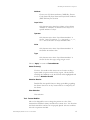
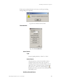
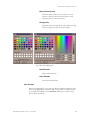
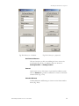
RITI-SICOM3_2-TECH-003
SICOM DISPLAY MODULE (SDM3.2)
STANDALONE
User’s Manual
October 15, 2001
274 Main Street, Suite 302
Reading, MA 01867
Tel/ 781.942.1655
Fax/ 781.942.2161
Website/ www.riti.com
E-mail:/ [email protected]
READING INFORMATION TECHNOLOGY INC.
SICOM Display Module Version 3.2 User Manual
1
SICOM Spatial Information Components
TABLE OF CONTENTS
I. What is Sicom Display Module (SDM)? ...................................................................................... 5
II. Using SDM ..................................................................................................................................... 5
File...................................................................................................................................................... 7
Open
...................................................................................................................................... 7
Close .............................................................................................................................................. 7
Redraw........................................................................................................................................... 7
Copy............................................................................................................................................... 7
Write Image .................................................................................................................................. 8
Print
....................................................................................................................................... 8
Plot Scale................................................................................................................................... 8
Fill Paper ................................................................................................................................... 8
Fit To Paper.............................................................................................................................. 9
Center on Paper ....................................................................................................................... 9
Print setup..................................................................................................................................... 9
Exit................................................................................................................................................. 9
View ................................................................................................................................................... 9
Toolbar .......................................................................................................................................... 9
Status.............................................................................................................................................. 9
Zoom ................................................................................................................................................. 9
By Rectangle
Step In
.......................................................................................................................... 9
.................................................................................................................................... 9
Step Out
................................................................................................................................. 9
Set Scale......................................................................................................................................... 9
Reset
....................................................................................................................................10
Pan....................................................................................................................................................10
Center at a Click
.................................................................................................................10
Step North
..........................................................................................................................10
Step South
...........................................................................................................................10
Step East
.............................................................................................................................10
Step West
.............................................................................................................................10
Reset
.....................................................................................................................................10
Window ...........................................................................................................................................10
Cascade........................................................................................................................................10
Tile Horizontally ........................................................................................................................10
Tile Vertically..............................................................................................................................11
Arrange Icons .............................................................................................................................11
Help..................................................................................................................................................11
SICOM Display Module Version 3.2 User Manual
2
SICOM Spatial Information Components
About SDM ................................................................................................................................11
Manual .........................................................................................................................................11
Tool..................................................................................................................................................11
Tool: Layer Annotator ............................................................................................................11
Select Layer.............................................................................................................................11
Layer in Active View.........................................................................................................11
LayerAnnotator......................................................................................................................11
Select column to annotate on ..........................................................................................12
Font .....................................................................................................................................12
Type face ........................................................................................................................12
Font size .........................................................................................................................12
Color................................................................................................................................13
Alignment ...........................................................................................................................13
Verticle............................................................................................................................13
Horizontal.......................................................................................................................13
Annotation Display Scale .................................................................................................13
Minimum ........................................................................................................................14
Maximum........................................................................................................................14
Line layers only ..................................................................................................................14
Stretch text .....................................................................................................................14
Fit text to curve .............................................................................................................14
Remove Annotation..........................................................................................................14
Tool : Layer Classifier ..............................................................................................................14
Select Layer.............................................................................................................................14
Layer in Active View.........................................................................................................14
Classify Layer..........................................................................................................................15
Column ...............................................................................................................................15
Classify by...........................................................................................................................15
Unique values.................................................................................................................16
Value ranges ...................................................................................................................16
Color....................................................................................................................................16
scheme ............................................................................................................................16
Remove classification............................................................................................................16
Classify ....................................................................................................................................16
Tool : Layer Prioritizer.............................................................................................................16
Layer Visibility........................................................................................................................16
Tool: Feature Selector..............................................................................................................17
Set Selection Color ................................................................................................................17
Set Selection Filter .................................................................................................................18
Feature Type ......................................................................................................................18
Attribute..............................................................................................................................19
Layer Value.........................................................................................................................19
Operator..............................................................................................................................19
Value....................................................................................................................................19
Type.....................................................................................................................................19
Select Feature(s) .....................................................................................................................19
Selection Results ....................................................................................................................19
Clear Selection........................................................................................................................19
SICOM Display Module Version 3.2 User Manual
3
SICOM Spatial Information Components
Tool: Feature Modifier.............................................................................................................19
FeatureModifier .....................................................................................................................20
Select Feature .....................................................................................................................20
Type.............................................................................................................................20
Select Feature.............................................................................................................20
Modifing Selected Feature................................................................................................20
Move Feature by Click .............................................................................................21
Change color..............................................................................................................21
Delete Feature ...........................................................................................................21
Clear Selection ...........................................................................................................21
Tool: Surveyor............................................................................................................................21
Get Points to Measure ..........................................................................................................22
Convert....................................................................................................................................22
Calculate Distance .................................................................................................................22
SICOM Display Module Version 3.2 User Manual
4
SICOM Spatial Information Components
I. What is Sicom Display Module (SDM)?
SICOM Display Module (SDM), a component of Spatial Information COMponents
(SICOM), can be deployed as a stand-alone independent program (SDM) or as a server
(referred to as SDM_Server) that provides GIS services to a client application (referred to as
Client). The look and feel of SICOM Display Module can easily be modified by SDM
Profiler (SP). To learn about SDM Profiler, please consult user manual, Profiler User’s
Manual.doc (RITI-SICOM3.2-TECH-005). This document concentrates on the Standalone
SDM. SDM_Server is discussed in the SDM Developer Reference Manual (html documents)
The major change in the design of SICOM3.2 from previous versions is to designate SDM
as a pure display and visualization spatial component. Two new auxiliary component
groups are introduced: SICOM Tool and SICOM Manager. A SICOM Tool consists of
modules designed for users to modify look and feel of the displayed spatial data and/or to
measure direction and distance measurements. A SICOM Manager is designed to perform a
collection of specific GIS functions such as collecting GPS tracks, managing routes, and etc.
These Tools and Managers are configurable components to be included as specified by
developers.
A new key feature of SDM 3.2 is the ability to display and manipulate ESRI’s shape data.
SICOM Data Profiler is an easy to use tool for developer to define a default look and feel of
the spatial data for a given application. The output of SICOM Data Profile is a ASCII
description file called Spatial Agent File (SAF) with extension .saf. This saf file is the input
file for SDM3.2. Currently, SICOM Data Profiler is available only for ESRI’s shape files
(Shapedata document). To produce a SAF for CARIS data, one could use CARIS
MapSmith.
This document describes the general usage of the standalone SDM3.2. The discussion also
includes 6 SICOM tools - Layer Annotator, Layer Classifier, Layer Prioritizer, Feature
Selector, Feature Modifier and Surveyor, and one SICOM Manager – Annotator.
II. Using SDM
Upon starting SDM, three possible configurations, shown as Figs, II.1, II.2 and II.3, may be
presented. These configurations are preset by the SICOM Profiler. Fig. III.1 is a Microsoft
SDI single document view without preloaded map file, while Fig. III.2 is the SDI view with a
preloaded map file. Fig. III.3 presents a MDI multiple document view that cannot be
preloaded and needs to be loaded by users.
At the lower right corner of each SDM view, a scale box shows the display scale of the map.
Each document view consists of a working window and an overview window, if it is so
configured by SDM Profiler. In addition, depending on the configured Profile file, the
Working window may be moved, resized or minimized; the Overview window may also be
moved, resized or minimized, within the working window. Except for File, View and
Help1, the availability of the remaining menu items on a given SDM view is optional
depending on whether they are configured by SDM Profiler or SICOM Tool or SICOM
manager are configured. Fig. III.3 shows all the menu items available on SDM 3.2. In the
remaining section that follows, all menu items are discussed
1
For clarity, bold faced Arial font is used to represent a menu item.
SICOM Display Module Version 3.2 User Manual
5
SICOM Spatial Information Components
Fig. II.1 SDI view without preloaded file
Fig. II.2 SDI view with a preloaded file
SICOM Display Module Version 3.2 User Manual
6
SICOM Spatial Information Components
Fig. II.3 MDI view
File
Open
to open a SAF.
Close
to close a SAF
Redraw
to redraw the existing view to clear objects created temporarily.
Copy
to copy the current view on the active SDM window to the clipboard so
that it can be pasted to another application, which supports “paste” from
clipboard
SICOM Display Module Version 3.2 User Manual
7
SICOM Spatial Information Components
Write Image
to write the current view on the active SDM window to a jpeg image. It
will bring up a standard save dialog box to save this image
Print
Print the map shown in the active window. Clicking Print, bring up a
print dialog box (Fig. II.4). As in most Microsoft window applications,
the printer can be chosen and its properties’ settings can be adjusted
using the Setup button. In the Options box,
Fig. II.4 Print
Plot Scale
This window becomes active, when No on the Fit To Paper is
checked. Select a scale from the pull-down window. If the
desired scale in not shown, select any scale first. A scale
refinement dialog box (Fig. II.5) will be presented, after you
click ok. Tpye in the desired print scale.
Fig. II.5 Scale Refinement
Fill Paper
SICOM Display Module Version 3.2 User Manual
8
SICOM Spatial Information Components
If Yes is checked, prints the maximal extent of the map
beyond the viewing window.
Fit To Paper
If Yes is checked, the entire content of the displayed window
will be printed, i.e. WYSWYG
Center on Paper
If Yes is checked, printed map will be centered.
Use the Colours box to choose the default .col or specify a
new .col. Set the print quality using Print Quality, and select
the number of copies to print using Copies.
Print setup
A standard MS window print setup dialog box
Exit
exits the program
View
Toolbar
check to view the icons tool bar.
Status
check to view the status bar
Zoom
By Rectangle
Zooms to a rectangular area, defined by dragging the mouse on either
the overview or working windows
Step In
Zoom in by 50%, i.e. display scale (1: display scale) is divided by 2.
Step Out
Zoom out by 50%, a percent, i.e., display scale (1: display scale) is
mutilpied by 2.
Set Scale
Type in a desired scale on the Scale Refinement dialog box (Fig. II.6),
and click “ok” to zoom the view to the given scale.
SICOM Display Module Version 3.2 User Manual
9
SICOM Spatial Information Components
Fig. II.6 Scale Refinement
Reset
Resets to the default view defined by SICOM Profiler
Pan
Center at a Click
Pans to a new view centered at the position clicked by the user
Step North
If selected, moves the view North by 50% of the extent of the
present view
Step South
If selected, moves the view South by 50% of the extent of the
present view
Step East
If selected, moves the view East by 50% of the extent of the
present view
Step West
If selected, moves the view West by 50% of the extent of the present
view.
Reset
Resets to the default view settings as defined by SICOM Profiler
Window
Cascade
Arrange multiple views in the window in the cascade mode.
Tile Horizontally
SICOM Display Module Version 3.2 User Manual
10
SICOM Spatial Information Components
Arrange multiple views in the window in the horizontal tile mode.
Tile Vertically
Arrange multiple views in the window in the vertical tile mode.
Arrange Icons
Arrange all minimized view windows in good order.
Help
About SDM
About SDM version.
Manual
Electronic version of this document
Tool
Tool: Layer Annotator
This tool is designed for annotating a field of the DBF file accompaning the
selected layer on the view.
Select Layer
Layer in Active View
Select a layer for annotation by moving cursor to and
pressing the left mouse key (Fig. II.7). click OK to bring
up Layer Annotator.
Fig.II.7 Select Layer
LayerAnnotator
SICOM Display Module Version 3.2 User Manual
11
SICOM Spatial Information Components
Fig. II.8 Layer Annotator
Select column to annotate on
Click to select an attribute (a column of the DBF file
that is associated with the shape layer) for annotation.
Font
Type face
Click
to select font.
Font size
If constant is not checked, the size of the font on
the view, S, is equal to D * (Map
Scale)/(Display_Scale * 1000) meters, where D
(in meter) is the chosen Font size, Map Scale is
the value entered in the shapefile Map
Parameters dialog box on SICOM Shape Data
Profiler (shown on the SAF file, after the key
word Map Scale:), and (Display Scale) is the view
scale (1: Map_Scale) on the monitor.
SICOM Display Module Version 3.2 User Manual
12
SICOM Spatial Information Components
Otherwise, the size of the font, S, is equal to
D/1000, on the monitor throughout all display
scales.
Color
This allows you to set the text color Click Set
Color to bring up the color dialog box, Fig.
III.5.3-3. You may choose the color from the
Basic color palette, or from the extensive color
dialog box (Fig. III.3-4) by clicking Define
Custom Color.
After you’ve chosen your color, click ok to return
to the Layer Annotator.
Fig II.9 Color
Fig. II.10 extensive color
Alignment
Verticle
Set text at the Center, bottom or top of the
reference point or line, where centroid for the
polygon and the location of the point.
Horizontal
Set text at the Center, left or right of the reference
points or line.
Annotation Display Scale
Allows you to specify a range of scales in which the
annotation will be visible.
SICOM Display Module Version 3.2 User Manual
13
SICOM Spatial Information Components
Minimum
To specify the larger scale (1: scale1), fill in scale1
Maximum
To specify the smaller scale (1: scale2), fill in
scale2. Fill in a value of “-1” to denote no upper
limit, i.e. visible in all scales.
Line layers only
Stretch text
This only applies to the “line” primitive. If
checked, the text will be stretched to the length of
the line.
Fit text to curve
This only applies to the “line” primitive. If
checked, the text will fit the curve of a line.
Remove Annotation
Removes the annotation.
Tool : Layer Classifier
This tool is designed for user to classify a chosen layer according to an
attribute on the accompanying DBF file.
Select Layer
Fig. II.11 Slect Layer
Layer in Active View
SICOM Display Module Version 3.2 User Manual
14
SICOM Spatial Information Components
Select a layer for annotation by moving cursor to and
pressing the left mouse key (Fig. II.11). click OK to bring
up Classify Layer (Fig. II.12)
Classify Layer
Fig. II.12 Classifier Layer
Column
Click to select an attribute (a column of the DBF file
that is associated the shape layer) for classification. If the
Unique values option on the section of the Classify by
panel is checked, only columns with unique value will be
available for selection.
Classify by
SICOM Display Module Version 3.2 User Manual
15
SICOM Spatial Information Components
Unique values
Classifies the primitives for the given layer
according to the unique value of the chosen
attribute.
Value ranges
Classifies the primitives for the given layer
according to classes defined by the chosen classes
in the Number of ranges.
Color
scheme
Choose a color scheme: Rainbow, grayscale,
custom. If custom is chosen, you may modify
the color of each class by clicking Edit Color.
Remove classification
Removes the classification
Classify
Apply classification
Tool : Layer Prioritizer
This tool is designed for user to modify the display priority of layers
Layer Visibility
This window shows the list of geo-registered data (layers) for this
application. The layer is visible, if the box next to it is checked.
Highlight the layer and use to move the layer up and down. The
layers are arranged in the order of drawing on the view, i.e. the
layer drawn before could be covered by the layer drawn later.
Clicking the Apply button to redisplay the view with the new
choice. To quit, click Cancel or
at the upper right corner
SICOM Display Module Version 3.2 User Manual
16
SICOM Spatial Information Components
Fig. II.13 LayerVisibility
Tool: Feature Selector
This tool is designed for user to inquiry information regarding a feature
Fig. 14 FeatureSelector
Set Selection Color
Bring up the standard color dialog box to choose color to highlight
selected feature (fig. II.15).
SICOM Display Module Version 3.2 User Manual
17
SICOM Spatial Information Components
Fig. 15 Color dialog box
Set Selection Filter
Set conditions on the type of features to be selected to reduce the
scope of search (Fig. 16).
Fig. II.16 Selection Filter
Feature Type
Choose one of five types of geometric features, Image,
Polygon, Lines, Symbols, and Labels, or all types for
selection.
SICOM Display Module Version 3.2 User Manual
18
SICOM Spatial Information Components
Attribute
Choose one of 5 feature attributes, CARIS Key, Feature
Code, Source ID, Layer Name and Layer Name Attribute
(DEF field ame) for selection
Layer Value
Only become active when Layer Name or Layer Name
Attribute of “Attribute” is chosen. Choose a layer or a
specific attribute of a layer.
Operator
Only become active when “Layer Name:Attribute” is
chosen. One of 5 operators, =, != (not equal), >, <, >=,
or <= can be chosen to set Layer Attribute value
Value
Only become active when “Layer Name:Attribute” is
chosen.Set an attribute value.
Type
Only become active when “Layer Name:Attribute” is
chosen. Set the value type, string, integer or real.
Choose “Apply” to return to FeatureSelector
Select Feature(s)
You have 15 seconds to click the mouse at a location or drag a
square (while you press on the left key) region. All the features
satisfying the conditions set by the features will be highlighted and
shown on Selection Results
Selection Results
Double Click the specific feature to bring up the dialog regarding
the feature. Note that “no key” means there is no unique key for
the feature.
Clear Selection
Clear selection
Tool: Feature Modifier
This tool is designed for user to change the position or color of the
transient lines and labels (name) created on the current view. It is often that
the labels created for contours are not properly placed. The user could use
this tool to reposition the label.
SICOM Display Module Version 3.2 User Manual
19
SICOM Spatial Information Components
If there are no transient features on the view, you will get a warning
message dialog box (Fig II.18).
Fig. II.18 No transient features Error
FeatureModifier
Fig. II.19 FeatureModifier
Select Feature
Type
Type of graphic primitives, “Name” or “Line”
Select Feature
Click this button, you have 30 seconds to select a
transient feature on the active view. To select a
transient, put the cursor on the line feature or at the
upper left corner of the name feature, and press the
left mouse key. The mouse symbol changes to .
Releasing the let key, the color of the selected feature
will change to red.
Modifing Selected Feature
SICOM Display Module Version 3.2 User Manual
20
SICOM Spatial Information Components
Move Feature by Click
Click this button, and move your cursor to a new
location. Clicking the new location will move the
selected feature to this new location.
Change color
Click this button to bring up the color dialog box (Fig.
II.20) to change the color of selected feature
Fig. II.20 Color dialog box
Delete Feature
Delete selected feature
Clear Selection
Clear the selected feature.
Tool: Surveyor
This tool is designed for user to measure distance between two points and
the bearing. Depending on whether map is on geodetic coordinate system
or a projected coordinate system, Surveyor dialog box is shown on Fig.
II21 or II.22, respectively.
SICOM Display Module Version 3.2 User Manual
21
SICOM Spatial Information Components
Fig. II.21 Surveyor – Geodetic
Fig. II.22 Surveyor – projected
Get Points to Measure
Click two locations or click one and drag the line to choose the
second point (Fig. II.22). Coordinate values are shown on
Starting Position and Ending Position.
Convert
Only become active, if the map is on projected coordinate system.
Click on Convert the geodetic coordinates are shown on the blank
window below (Fig. 11.23)
Calculate Distance
Calculated distance and Bearing are showon on the blank window
below (Fig. II.24)
SICOM Display Module Version 3.2 User Manual
22
SICOM Spatial Information Components
Fig. II. 22 Measurement
Fig. II.23 Surveyor
SICOM Display Module Version 3.2 User Manual
Fig. 24 Calculated Distance
23