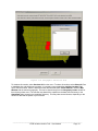
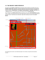
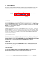
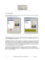
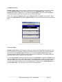
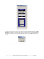
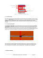
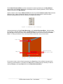
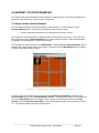
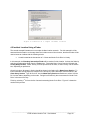
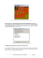
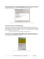
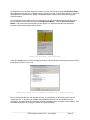
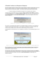
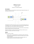
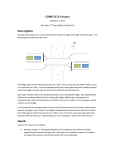
1
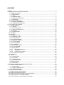
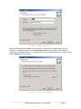
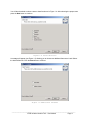
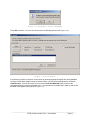
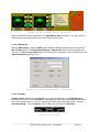
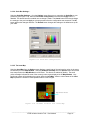
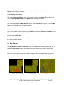
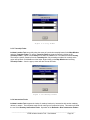
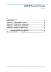
Incident Location Tool 4.X
User’s Manual
CONTENTS
Contents ........................................................................................................................................................ 3
1.0 INSTALLATION and CONFIGURATION ................................................................................................ 1
1.1 Installation Procedure......................................................................................................................... 1
1.1.1 Requirements............................................................................................................................... 1
1.1.2 Setup............................................................................................................................................ 1
1.1.3 Restart Message.......................................................................................................................... 5
1.1.4 Application Maintenance.............................................................................................................. 5
1.1.5 Uninstalling .................................................................................................................................. 6
1.2 Configuring Geography ...................................................................................................................... 7
1.2.1 First-time Configuration ............................................................................................................... 7
1.2.2 Geography Reconfiguration....................................................................................................... 14
2.0 The Graphic User Interface.................................................................................................................. 15
2.1 Command Buttons............................................................................................................................ 16
2.1.1 View All ...................................................................................................................................... 16
2.1.2 Previous/Next View.................................................................................................................... 16
2.1.3 Zoom In and Zoom Out.............................................................................................................. 16
2.1.4 Pan Map..................................................................................................................................... 16
2.1.5 Locate Incident........................................................................................................................... 16
2.2 Status Bar......................................................................................................................................... 17
2.3 Menu Bar .......................................................................................................................................... 17
2.3.1 Menu Bar > File ......................................................................................................................... 17
2.3.2 Menu Bar > Tools ...................................................................................................................... 17
2.3.2.1 Layer Settings .......................................................................................................................... 18
2.3.2.2 Setup Geography.................................................................................................................... 19
2.3.3 Menu Bar > Options................................................................................................................... 19
2.3.3.1 GPS Tracking.......................................................................................................................... 19
2.3.3.2 GPS Settings…....................................................................................................................... 20
2.3.3.3 Scale Bar ................................................................................................................................ 20
2.3.3.4 Scale Bar Settings…............................................................................................................... 21
2.3.3.5 The Inset Map ......................................................................................................................... 21
2.3.3.6 Map Extents ............................................................................................................................ 22
2.3.3.7
Easting and Northing ......................................................................................................... 22
2.3.3.8
Map Scale .......................................................................................................................... 22
2.3.3.9
Label Finder Locations ...................................................................................................... 22
2.3.3.10 Clear Finder Labels .............................................................................................................. 22
2.4 Map Window..................................................................................................................................... 22
2.5 Finders.............................................................................................................................................. 23
2.5.1 County Finder ............................................................................................................................ 23
2.5.2 City Finder.................................................................................................................................. 23
2.5.3 Township Finder ........................................................................................................................ 24
2.5.4 Intersection Finder ..................................................................................................................... 24
2.5.5 Milepost Finder ........................................................................................................................... 27
2.5.6 Point Finder................................................................................................................................ 27
3.0 Locating an Incident Using Incident Location Tool ............................................................................... 29
3.1 Incident Placement Menu................................................................................................................. 29
3.1.1 Locate Incident............................................................................................................................ 30
3.1.1 Snap On and Snap Off .............................................................................................................. 30
3.1.2 Measure Settings ....................................................................................................................... 30
4.0 Incident Location Examples .................................................................................................................. 32
4.1 Simple Incident Location Example .................................................................................................... 32
4.2 Incident Location Using a Finder....................................................................................................... 33
4.3 Measuring an Incident Location from an Intersection ....................................................................... 34
4.4 Incident Location on a Divided Roadway .......................................................................................... 36
4.5 Incident Location on an Overpass or Underpass .............................................................................. 38
1.0 INSTALLATION AND CONFIGURATION
1.1 Installation Procedure
1.1.1 Requirements
The CTRE Incident Location Tool can be installed from a CD-ROM or over a network. The program
runs on Windows 9X, NT, 2000, and XP operating systems and may require up to XX megabytes of free
disk space. The CTRE Incident Location Tool functions as an extension of the Iowa Department of
Transportation’s Traffic and Criminal Software (TraCS). Please consult TraCS documentation for
information on how to start the Incident Location Tool from within TraCS.
1.1.2 Setup
Double click LOCTOOL.EXE on the CD-ROM setup disk. A screen will appear as shown in Figure 1.1
Figure 1.1 CTRE Location Tool Setup
Click the Next button. A screen will appear allowing you to enter information to personalize your
installation. This screen is shown below in Figure 1.2.
________________________________________________________________________
CTRE Incident Location Tool – User Manual
Page 1
Figure 1.2 User Information
After you are satisfied click the Next button to continue. You will receive a message (see Figure 1.3)
allowing you to change the directory that Incident Location Tool will be installed in OR to begin the
installation using the default directory. It is suggested that you use the default directory. To do this, simply
press the Next button on the screen.
Figure 1.3 Destination Folder
________________________________________________________________________
CTRE Incident Location Tool – User Manual
Page 2
You will then be asked to select a state to install as shown in Figure 1.4. After selecting the proper state
press the Next button to continue.
Figure 1.4 State Selection
A message will appear (see Figure 1.5) allowing you to choose two additional features to install. Select
the desired features. Click the Next button to continue.
Figure 1.5 Additional Features
________________________________________________________________________
CTRE Incident Location Tool – User Manual
Page 3
A message will appear (see Figure 1.6) allowing you to start the installation or move back to change
setup information. Once you are ready to start the installation press the Next button.
Figure 1.6 Begin Installation
During the installation a message will appear showing the progress of installation as shown in Figure 1.7.
Figure 1.7 Installation Progress
You will know the installation was successful by seeing the message shown in Figure 1.8.
________________________________________________________________________
CTRE Incident Location Tool – User Manual
Page 4
Figure 1.8 Installation Successful
1.1.3 Restart Message
If your operating system is missing certain system files or has old versions of certain files, the installation
may ask you to restart the machine and run setup.exe again. This does not mean that there is anything
wrong with your machine or with the installation. It indicates that the Incident Location Tool requires
additional or more recent files; these will be installed automatically. The new files will be activated upon
restart.
1.1.4 Application Maintenance
If an installation is already present (see Figure 1.9) the following message will appear. Three options are
available. You can Modify application features; Repair missing or corrupt files, registry keys, and
shortcuts; or Remove the application from your machine.
________________________________________________________________________
CTRE Incident Location Tool – User Manual
Page 5
Figure 1.9 Application Maintenance
1.1.5 Uninstalling
Double click LOCTOOL.MSI on the CD-ROM setup disk. A message (see Figure 1.9) will appear on the
screen. Select the Remove option and press the Next button. A message will appear (see Figure 1.10) to
confirm the removal of the application. Press the Next button to continue with uninstalling.
Figure 1.10 Application Uninstall
________________________________________________________________________
CTRE Incident Location Tool – User Manual
Page 6
A successful uninstall will be confirmed by seeing the message shown in Figure 1.11.
Figure 1.11 Successful Uninstall
1.2 Configuring Geography
1.2.1 First-time Configuration
The first time you launch the Incident Location Tool from TraCS (see TraCS documentation for how to
do this), you may get a message (see Figure 1.12) prompting you to “Setup Geography,” the process by
which the county data files are installed into the map data folder.
Figure 1.12 Geography Setup
Press OK to continue. If the program has difficulty finding the source directory that contains the statewide
map files, you will be prompted (see Figure 1.13) to help locate the directory (on the CD drive, network, or
local machine).
________________________________________________________________________
CTRE Incident Location Tool – User Manual
Page 7
Figure 1.13 Proceed to Locate Geography
Press OK to continue. You must now choose from the following options (see Figure 1.14).
Figure 1.14 File Search
If the directory location is unknown, search drives by choosing appropriate option and clicking Search.
Once the file has been obtained using the search feature, you choose the appropriate file and select
Load Directory. If the file is known, you may select Locate File Manually and then point to the
appropriate directory using the dropdown menu. It is important to remember that in order to load the file,
the folder must appear to be open as in Figure 1.15.
________________________________________________________________________
CTRE Incident Location Tool – User Manual
Page 8
Figure 1.15 Manual Location of Directory
________________________________________________________________________
CTRE Incident Location Tool – User Manual
Page 9
You should then see the Geography Loader map like the one in Figure 1.16.
Figure 1.16 Geography Configuration Map
By running the mouse pointer over the map, the counties will highlight yellow and their names will appear.
Click on the county or counties whose data you wish to use. They will turn red on the map. To deselect,
click again, the county will turn back to the previous color.
________________________________________________________________________
CTRE Incident Location Tool – User Manual
Page 10
Click the right mouse button to access the following drop down menu shown in Figure 1.17.
Figure 1.17 Selecting a County
If you do not know the map location of a county, they may be selected by choosing the appropriate Select
County option on the drop down menu. This will provide an alphabetical listing of counties to choose from
(see Figure 1.17). County regions may also be selected by moving the pointer over Select Patrol
Regions. A list showing the regions will appear and may be selected from as shown below in Figure 1.18.
________________________________________________________________________
CTRE Incident Location Tool – User Manual
Page 11
Figure 1.18 Selecting a Patrol Region
A list of the selected counties and or regions may be viewed by selecting View Selection List from the
drop down menu. A list will appear as shown below in Figure 1.19.
________________________________________________________________________
CTRE Incident Location Tool – User Manual
Page 12
Figure 1.19 Geographic Selection LIst
To deselect all counties, select Unselect All from the menu. To select all counties, select Select All. Due
to database size and performance reasons, it is strongly recommended that Incident Location Tool
never load all counties. After the desired counties are selected select Create Dataset to load the Map
Window with the selected geography. This can be done directly from the Geography Loader window or
from the drop down menu. The relevant map data will be copied from the data source directory to the
ShapeData folder located in the installation directory. This may take several minutes, depending on the
amount of data and the speed of your machine.
________________________________________________________________________
CTRE Incident Location Tool – User Manual
Page 13
1.2.2 Geography Reconfiguration
You can reconfigure your geography at any time as long as you have access to the source data directory
with the statewide map files. Go to the Tools pull-down menu on the top Menu Bar and select Setup
Geography, as in Figure 1.20. The Geography Loader map will appear.
Figure 1.20 Setup Geography in Tools pull-down menu
________________________________________________________________________
CTRE Incident Location Tool – User Manual
Page 14
2.0 THE GRAPHIC USER INTERFACE
All interaction with Incident Location Tool is performed through the graphic user interface (GUI). The
Incident Location Tool is designed to minimize complexities often encountered when using geographic
information system (GIS) software and provide a simple way to locate crashes and other incidents. The
interface consists of a Map Window, an Inset Map, Command Buttons, a Scale Bar, a Menu Bar, and
a Status Bar (Figure 2.1). Users should at least be familiar with the Command Buttons.
At the simplest level, Incident Location Tool only requires the use of the Command Buttons to locate a
crash or incident. More experienced users will find other features useful for more quickly finding particular
geographic areas. These features are discussed in depth within subsequent sections of this User
Manual.
Command Buttons Toolbar
Main Map Window
Menu Bar
Scale Bar
Inset Map
Status Bar
Figure 2.1 Location Tool User Interface
The following sections offer more detailed description of the interface components and their basic
functions.
________________________________________________________________________
CTRE Incident Location Tool – User Manual
Page 15
2.1 Command Buttons
As previously mentioned, all actions necessary to locate an incident can be accessed using the seven
command buttons shown in Figure 2.2. Six of the seven buttons perform specific map operations.
Previous/Next View
Zoom In/Out
Locate Incident
View All
Pan View
Figure 2.2 Command Button Toolbar
2.1.1 View All
Pressing the View All button displays the Map Window’s full extent. At this level, not much detail is
shown in the Map Window. More detailed map information is displayed to the user as the Map Window
is zoomed to a subset of its entire extent. Operate by clicking with the left mouse button. When the Map
Window is at full extent this button is disabled.
2.1.2 Previous/Next View
Incident Location Tool saves the extent of the Map Window as the map view changes. Pressing the
Previous or Next buttons will show the previous or next map view held in the extent collection. Operate
by clicking with the left mouse button. These buttons disable when the current map extent shown is the
first or last in the collection. This functionality is exactly similar to that of Forward and Back buttons
common to web browser software.
2.1.3 Zoom In and Zoom Out
These buttons allow a user to manipulate the map extent with the mouse. Operate by clicking with the
left mouse button. With Zoom In enabled, holding down the left mouse button will draw a rectangle
indicating the desired map extent. Clicking either the Zoom In or Zoom Out once will change the map
extent by a predefined amount. When the Map Window is at full extent the Zoom Out button is disabled.
The Zoom In button is automatically selected when the Full Extent button is depressed.
2.1.4 Pan Map
This button also allows a user to move the Map Window left, right, up, or down without changing the
zoom extent. Operate by clicking with the left mouse button. Once enabled, click and hold down the left
mouse button on the Map Window and drag the mouse in the direction desired. This button is also
disabled when the Map Window is at full extent.
2.1.5 Locate Incident
This button places Incident Location Tool in Incident Location Mode. The use of this button is
described in detail in the section Locating an Incident Using Incident Location Tool.
________________________________________________________________________
CTRE Incident Location Tool – User Manual
Page 16
2.2 Status Bar
Information about the Map Window’s current extents and the X/Y position of the mouse cursor appears
in the Status Bar (Figure 2.3). The current scale of the Map Window is also shown in the Status Bar.
Use these tools to record specific X and Y coordinates and to know the span of the Map Window extent.
Map Window Extent
(in miles)
X Coordinate of
Cursor
Y Coordinate of
Cursor
Figure 2.3 Status Bar
Map Scale
(*in miles)
*Note: will change based on Scale Bar units
2.3 Menu Bar
The Incident Location Tool GUI settings and tools can be accessed using the Menu Bar located just
above the Command Buttons (see Figure 2.4). The specific functions associated with each menu are
detailed in the following sections.
Figure 2.4 Menu Bar
2.3.1 Menu Bar > File
This menu has three options (see Figure 2.5). Select Save Map… to access a dialog box allowing you to
save the current map. Select Print Map… to access a dialog box allowing you to print the current map.
To exit the software and quit locating incidents select Exit.
Figure 2.5 Menu Bar > File Selection
2.3.2 Menu Bar > Tools
The Tools menu option provides various functions assisting users (see Figure 2.6). The Finders option
provides many tools to facilitate rapid location of specific geography. The use of each finder is detailed
in section 2.5 Finders.
________________________________________________________________________
CTRE Incident Location Tool – User Manual
Page 17
Figure 2.6 Menu Bar > Tools Selection
2.3.2.1 Layer Settings
The Layer Settings menu option (see Figure 2.7) allows users to change the way the various layers in
the Incident Location Tool are viewed.
Figure 2.7 Menu Bar > Tools > Layer Settings
The Layers tab allows users to change the colors and visibility of the map layers in Incident Location
Tool. The Layers tab allows users to make layers invisible by clearing the Visible box and allows users
to specify the Outline color of each layer.
The Labels tab allows users to change the label color of map features (i.e. street names, county names,
city names) in Incident Location Tool. In addition to color changes, the Labels tab also allows users to
change font type and size. Just like the Layers tab, the Labels tab offers the option to make individual
labels invisible by choosing the appropriate label and clearing the Visible box. One additional feature
that the Labels tab offers is the option to have Splined Text (See Figure 2.8). This is accomplished by
checking the Splined Text box for the appropriate label.
The OK button exits the Layer Control screen and saves the applied changes. The Apply button
applies the changes that the user has made. The Reset button changes the settings back to those
present before Layer Settings was accessed. The Cancel button allows users to exit the Layer Control
screen without making changes.
________________________________________________________________________
CTRE Incident Location Tool – User Manual
Page 18
Figure 2.8 Splined Text Vs. Non-Splined Text
2.3.2.2 Setup Geography
The Setup Geography menu option allows the user to change the currently active region using the
Geography Configuration Map. Detailed instructions for changing geography are located in section
1.2.2 Geography Reconfiguration
2.3.3 Menu Bar > Options
Figure 2.9 Menu Bar > Options Selection
2.3.3.1 GPS Tracking
Incident Location Tool is equipped to support direct interface with GPS equipment. This functionality
enables the location of a vehicle to be displayed in the Map Window and allows the extent of the map to
be moved as the position of the vehicle changes. GPS Tracking can be enabled or disabled by selecting
GPS Tracking from under the Options menu (see Figure 2.10).
________________________________________________________________________
CTRE Incident Location Tool – User Manual
Page 19
Figure 2.10 GPS Tracking Console and Locater
There are options that can be configured on the Right Display Bank (see Figure 2.10). There is also a
locater shown on the map pointing to the current location of your signal.
2.3.3.2 GPS Settings…
Selecting GPS Settings… from the Options menu displays a dialog box allowing you to configure the
GPS Tracking options. The Configuration Manager – GPS Console dialog box is shown below (see
Figure 2.11). Enabling Pop-Up Menu allows you to access the configuration menu by right clicking on the
Right Display Bank (see Figure 2.10).
Figure 2.11 Configuration Manager – GPS Console
2.3.3.3 Scale Bar
Incident Location Tool displays a Scale Bar in the upper right-hand corner of the Map Window for
reference (see Figure 2.12). The Scale Bar is fixed length and represents a specified distance within the
map. As the map is zoomed in or out, the scale bar will update to the current map extents. Selecting
Scale Bar Settings… from the Options menu will allow you to configure the Scale Bar.
Figure 2.12 Scale Bar
________________________________________________________________________
CTRE Incident Location Tool – User Manual
Page 20
2.3.3.4 Scale Bar Settings…
Selecting Scale Bar Settings… from the Options menu allows you to customize the Scale Bar to your
preference (see Figure 2.13). When the Scale Bar Configuration is accessed the Apply button is
disabled. This button becomes enabled once a change is made. The Cancel button will exit and change
the settings to the precious Apply or to those present before the configuration was accessed. The OK
button applies the changes and exits. The Default button changes the settings to the defaults set up for
your state.
Figure 2.13 Scale Bar Configuration
2.3.3.5 The Inset Map
Selecting Inset Map from the Options menu displays a small map of the entire active region in the upper
left-hand corner of the Map Window. Selecting Autohide Inset Map from the Options menu will turn the
inset map off when the Map Window is at full-extent. This feature is enabled by default. The small
yellow rectangle indicates the area of the currently active region displayed in the Map Window. Very
small map extents will be displayed as a point within the Inset Map. Maroon colored areas of the Inset
Map represent the location of municipalities within the active region.
Map Window Extent
Figure 2.14 Incident Location Tool Inset Map
________________________________________________________________________
CTRE Incident Location Tool – User Manual
Page 21
2.3.3.6 Map Extents
The current Map Extent is shown in the Status Bar (see Figure 2.3). Selecting Map Extents from the
Options menu will toggle its visibility.
2.3.3.7 Easting and Northing
The current Easting and Northing of the cursor position is shown in the Status Bar (see Figure 2.3).
Selecting Easting and Northing from the Options menu will toggle its visibility.
2.3.3.8 Map Scale
The current Map Scale of the Map Window is shown in the Status Bar (see Figure 2.3). Selecting Map
Scale from the Options menu will toggle its visibility.
2.3.3.9 Label Finder Locations
The Finder tools are used to find locations on the map easily. Labels will be placed on the map allowing
you to quickly find the locations found using the Finder tools. Selecting Label Finder Locations from the
Options menu will toggle the visibility of these labels.
2.3.3.10 Clear Finder Labels
Selecting Clear Finder Labels will remove all previous labels from Incident Location Tools memory and
they will no longer be available.
2.4 Map Window
The Map Window of Incident Location Tool is the main interface point between software and user. All
location operations are performed on the Map Window. While locations are designated on highways and
streets, the Map Window contains other spatial data layers to assist users in finding specific map
locations.
Layers will vary based on how Incident Location Tool is configured for your state. Layers include
information concerning the location of county and corporate limits, rivers and streams, highways and
streets, townships, sections, and milepost marker locations. Example layers are shown below.
i. County and City Borders
ii. Rivers and Lakes
iii. Streets
________________________________________________________________________
CTRE Incident Location Tool – User Manual
Page 22
iv. Railroads
v. Townships and Sections
vi. Milepost Markers
Figure 2.15 Map Layer Details
2.5 Finders
Incident Location Tool provides functionality to query specific features contained in each Map Window
layer. Incident Location Tool does this through software tools called Finders. The functions offered by
each finder are detailed below.
2.5.1 County Finder
Incident Location Tool can quickly show the extent of a particular county located in the Map Window
using the County Finder. To use the County Finder, activate the finder by clicking on the County
Finder… option of the Finders menu under the Tools menu. Select a specific county from the County
List. Only counties contained in the currently active region will be listed. Click Close to exit the finder.
Right clicking on the Map Window and selecting the County Finder… from the pop-up menu will also
access this finder.
Figure 2.16 County Finder
2.5.2 City Finder
Incident Location Tool can quickly show the extent of a particular city located in the Map Window using
the City Finder. To use the City Finder, activate the finder by clicking on the City Finder… option of the
Finders menu under the Tools menu. First select the desired County. Then select a specific city from
the City List. Only cities contained in the selected County will be listed. Click Close to exit the finder.
Right clicking on the Map Window and selecting City Finder… from the pop-up menu will also access
this finder.
________________________________________________________________________
CTRE Incident Location Tool – User Manual
Page 23
Figure 2.17 City Finder
2.5.3 Township Finder
Incident Location Tool can quickly show the extent of a particular township located in the Map Window
using the Township Finder. To use the Township Finder, activate the finder by clicking on the
Township Finder… option of the Finders menu under the Tools menu. First select the desired County.
Then select a specific township from the Township List. Only townships contained in currently active
region will be listed. Click Close to exit the finder. Right clicking on the Map Window and selecting
Township Finder… from the pop-up menu will also access this finder.
Figure 2.18 Township Finder
2.5.4 Intersection Finder
Incident Location Tool supports the lookup of roadway locations by intersection with another roadway,
railroad, or stream. Three separate tools exist for each type of intersection lookup. This section will detail
the use of the Roadway Intersection Finder. Operation of the Railroad or River Intersection Finders
________________________________________________________________________
CTRE Incident Location Tool – User Manual
Page 24
will work in the same manner. Figure 2.19 shows the Roadway Intersection Finder and identifies its
features. Each of the intersection finders is accessed from the appropriate item on the Finder menu
under the Tools menu.
Each intersection finder is divided into separate Query Sections, each displaying a different database
attribute. Intersections are located by successively narrowing the roadway features from the currently
active region using the database fields found in each Query Section. Selecting an item from a Query
Section automatically reloads all sections below it with a smaller subset of the entire database. For
example, selecting a city name from the City Select Query Section will cause all Query Sections below
it to contain items relating only to the selected city. To refill Query Sections with all data for the currently
active region, select an item from the topmost County Select Query Section.
Toggle Switch
Figure 2.19 Intersection Finder for Roadways
The Intersection Finder supports both the selection of database item names from a Drop-down List
and the direct key-in of item names from a Searchbox. The List/Search Toggles located on each
Query Section of the finder switch between these modes (see Figure 2.19). The icon on each
List/Search Toggle indicates the current mode of each Query Section.
Names typed in while in Search Mode must appear exactly the way as they appear in the database. If a
name is not in the database, the search text being typed will turn red in color (see Figure 2.20). Notice the
change in Toggle Switch icon. To see the first, most-similar text found in the database, toggle over to
List Mode. This is useful if the text you are typing begins black but turns red after a few letters are
entered. Backspacing until the letters once again turn black, and then toggling over to List Mode, will
show the most-similar item in the database.
________________________________________________________________________
CTRE Incident Location Tool – User Manual
Page 25
Black Valid Entry
(Database contains ‘WELCH AVE’)
Red Invalid Entry
(Database does not contain
‘WELCH ST’)
Figure 2.20 Example of valid and invalid database searches
The Intersection Finder automatically finds a location on the map once a valid selection is made from
each Query Section on the Finder. Right clicking on the Map Window and selecting the appropriate
Intersection Finder from the pop-up menu will also access the finders. The Road/Rail and Road/River
Intersection Finders are shown below (see Figures 2.21 and 2.22).
Figure 2.21 Intersection Finder for Railroads
Figure 2.22 Intersection Finder for Rivers
________________________________________________________________________
CTRE Incident Location Tool – User Manual
Page 26
2.5.5 Milepost Finder
Incident Location Tool provides support for finding map locations using primary road milepost markers.
To use the Milepost Finder, activate the finder by clicking on the Milepost Finder… option of the
Finders menu under the Tools menu. First select the desired County. Then select the desired Route.
Only milepost markers pertaining to the above two selections will be listed.
Finally, select a particular Milepost marker from the Milepost List. Click Close to exit the finder. Right
clicking on the Map Window and selecting Milepost Finder… from the pop-up menu will also access this
finder.
Figure 2.23 Location Tool Milepost Finder
2.5.6 Point Finder
Incident Location Tool provides support for finding map locations using handheld GPS equipment. The
GPS unit must first be configured to output coordinate units that are from the same projection and datum
as that used by the Incident Location Tool base map. Currently Incident Location Tool is using a
Universal Transverse Mercator Projection and the North American 1983 Datum. All handheld GPS units
tested were able to output coordinates in this projection.
To use the Point Finder, activate the finder by clicking on the Point Finder… option of the Finders menu
under the Tools menu. Enter coordinates (Long/Lat or Projected NAD83) to locate by using the keyboard
or the command buttons on the form. When finished, click the Find button using the left mouse button.
To exit the finder without locating a point, click the Close button. Right clicking on the Map Window and
selecting Point Finder… from the pop-up menu will also access this finder.
________________________________________________________________________
CTRE Incident Location Tool – User Manual
Page 27
Figure 2.24 Point Finder
If the point entered is valid for the currently active region, the location entered will be centered in the Map
Window and the map will zoom in closer to the vicinity of the entered point. If the coordinates entered do
not represent a valid map point an error message will appear (Figure 2.25). Click OK to close the error
message.
Figure 2.25 Invalid Coordinates Error Message
________________________________________________________________________
CTRE Incident Location Tool – User Manual
Page 28
3.0 LOCATING AN INCIDENT USING INCIDENT LOCATION TOOL
Crashes are located in Incident Location Tool using the left mouse button and the Command Button
Toolbar’s Locate Incident button. The Locate Incident button must be depressed before a location can
be designated.
Locate Incident
Figure 3.1 Locate Incident Button
Pressing this button enables Incident Location Mode. While in Incident Location Mode, the software
will dynamically label features on the Map Window. If the mouse cursor is near the intersection of
differing streets, Incident Location Tool will include both street names in the dynamic label. The label
displayed includes all available street designations from the roadway database. Street names can include
city, county, 911, and primary route designations. Incident Location Tool determines which names are
appropriate to display based on the DOT functional classification of each roadway.
Dynamic Label
Figure 3.2 Dynamic Labeling of Highway/Street Names
3.1 Incident Placement Menu
All incident locations are designated while in Incident Location Mode. All location functions are
accessible through a pop-up menu called the Incident Placement Menu. The Incident Placement
Menu will only display when the software is placed in Incident Location Mode. To display the Incident
Placement Menu, click the left mouse button while over the Map Window. The Incident Placement
Menu provides access to all commands necessary for location designation. Figure 3.3 shows the
Incident Placement Menu as it appears over the Map Window.
________________________________________________________________________
CTRE Incident Location Tool – User Manual
Page 29
Locate Incident
Snap On/Off
Measuring Options
Figure 3.3 Incident Placement Menu
3.1.1 Locate Incident
This menu command controls when and where an incident location will be designated. When the mouse
cursor in the Map Window best represents the location of the incident being identified, select the Locate
Incident menu item to designate the crash. Several forms may appear depending on the location
designated. Each possible type of scenario is discussed in detail in the section entitled Incident Location
Examples.
3.1.1 Snap On and Snap Off
The Snap On and Snap Off menu commands control how the mouse pointer behaves during Incident
Location Mode. If Snap On is enabled, movement of the mouse pointer near roadway segments in the
Map Window will cause the mouse to ‘snap’ or move directly on top of the nearest line segment (see
Figure 3.4). This feature is intended to ensure that locations designated using Incident Location Tool lie
exactly on DOT centerline cartography, an important requirement for roadway safety analyses.
Snap Point
Figure 3.4 Mouse Cursor ‘Snapping’ to Intersection
The snap feature is enabled by default and should normally be left on. Special circumstances occur
when snap may need to be disabled. These events are discussed in Measuring an Incident Location
from an Intersection in the Incident Location Examples section. To disable snap, click Snap Off.
3.1.2 Measure Settings
________________________________________________________________________
CTRE Incident Location Tool – User Manual
Page 30
The Incident Placement Menu provides commands for measuring distances on the Map Window.
Menu options are available to specify the units displayed when measuring distances, and to enable or
disable measuring in the Map Window.
Specify measure units using the Measure Units sub-menu. By default Incident Location Tool measures
distances in feet. Select an alternate distance unit using the left mouse button to select an option.
Measure settings persist and are not reset after the software shuts down.
Figure 3.5 Measure Unit Settings
Activate measuring by clicking Enable Measuring on the Incident Placement Menu. A black triangle
will be drawn in the Map Window indicating the Start Point of any measures made (see Figure 3.6). A
label will appear next to the mouse cursor indicating the distance of the mouse cursor from the Start
Point. To change the distance units, use the procedure mentioned in the previous section.
Start Point
Measured Distance
Snap Point
Dynamic Street Label
Figure 3.6 Measure Tool in use
If the cursor is near a vertex of two line segments, the Snap feature of the software may prevent the
measuring of small distances. By Default, the Snap feature is disabled during measuring. If desired,
reactivate Snap by choosing Snap On from the Incident Placement Menu.
________________________________________________________________________
CTRE Incident Location Tool – User Manual
Page 31
4.0 INCIDENT LOCATION EXAMPLES
This section of the manual illustrates several examples of incident location. All of these examples were
performed using either Story or Polk County in central Iowa.
4.1 Simple Incident Location Example
The first example illustrates the simplest incident location scenario. For this example, only the
Command Buttons will be used to locate an incident with the following criteria:
•
A crash located at the intersection of 9th Street and Duff Avenue in Ames.
In this example it is assumed that the incidents location is well known by the Locator. This is the most
likely time when only the Command Buttons will be used to locate an incident. Other tools exist within
the software for the designation of lesser know locations.
The first step is to find this location on the Map Window. Using the Zoom In Command Button, draw a
rectangle in the approximate location; zoom again, if necessary to fill the Map Window with the location.
Figure 4.1 shows the location as found.
Figure 4.1 Intersection where incident occurred
Once the vicinity of the incident has been located, enter Incident Location Mode by clicking on the
Locate Incident button on the Command Button Toolbar. To designate the location of the incident left
click on the Map Window when the snapped cursor is exactly in the intersection and select Locate
Incident from the Incident Placement Menu. A form should appear similar to the one shown in Figure
4.2. This ends the example of simple incident location.
________________________________________________________________________
CTRE Incident Location Tool – User Manual
Page 32
Figure 4.2 Results of a simple incident location
4.2 Incident Location Using a Finder
The second example illustrates a more complex incident location scenario. For this example it will be
assumed that the location on the map where the incident occurred is not known, therefore a finder will be
used to locate an incident with the following criteria:
•
A crash located at the intersection of 1st Street and North Circle Drive in Huxley.
In this example, the Roadway Intersection Finder will be used to find the location. Activate the finder by
selecting the appropriate finder from the Tools menu. First select Story County from the left hand side
County Query Section. Select ‘Huxley’ from the pull-down list of cities, or enter ‘Huxley’ into the search
box, depending on preference.
Once this is done, all streets in Huxley should be shown in the listbox of the Name Query Section. To
further eliminate US highways from inclusion in the final query, select ‘Municipal’ from the listbox in the
Class Query Section. Type ‘N Circle Dr’ into the Name Query Section’s searchbox or select ‘N Circle
Dr’ from the listbox, depending on the mode. Doing this will load only the cross streets for ‘North Circle
Drive’ in the town of Huxley.
Finish by selecting ‘1st St’ from the list of streets intersecting North Circle Drive. Figure 4.3 shows the
results of this process.
________________________________________________________________________
CTRE Incident Location Tool – User Manual
Page 33
Figure 4.3 Location found using Intersection Finder
Once the vicinity of the incident has been located, enter Incident Location Mode by clicking on the
Locate Incident button of the Command Button Toolbar. To designate the location of the incident left
click on the Map Window when the snapped cursor is on the intersection and select Locate Incident from
the Incident Placement Menu. A form should appear similar to the one shown in Figure 4.4. This ends
the example of using a finder to locate an incident.
Figure 4.4 Results of a simple incident location
4.3 Measuring an Incident Location from an Intersection
The third example illustrates an incident location scenario where the incident occurred a known distance
from an intersection. For this example, the location where the incident occurred will be the same as the
previous example. The incident has the following criteria:
________________________________________________________________________
CTRE Incident Location Tool – User Manual
Page 34
•
A crash on 1st Street measuring 120 feet East from the intersection of 1st Street and North
Circle Drive in Huxley.
Locate the intersection of 1st Street and North Circle Drive using the Command Buttons or a finder.
Place the mouse cursor at the intersection of the two streets and left click on the Map Window. The
Incident Placement Menu should appear as shown in Figure 4.5.
Figure 4.5 Beginning a measure operation from the Incident Placement Menu
Select Enable Measuring to begin measuring. Move the mouse cursor east until the distance indicates
that the mouse cursor is 120 feet away from the Start Point. Limitations of screen resolution may
prevent the actual distance of ‘120 Feet’ being seen while measuring. If this occurs, simply select the
distance best approximating the actual measured distance, or zoom the Map Window in closer for higher
resolution. Figure 4.6 shows how close the screen resolution permitted the measuring of 120 feet.
Figure 4.6 Locating an Incident 120 Feet from an intersection
________________________________________________________________________
CTRE Incident Location Tool – User Manual
Page 35
Once the appropriate distance has been measured from the intersection, right click the mouse and select
the Locate Incident button on the Incident Placement Menu to designate the location. A form should
appear similar to the one shown in Figure 4.7. This ends the measuring example.
Figure 4.7 Results of a measurement from an intersection
4.4 Incident Location on a Divided Roadway
The fourth example illustrates an incident location scenario where the incident occurs on a four-lane
divided highway. When an incident is placed on a divided section of roadway, the software prompts the
user to indicate which set of lanes the incident occurred on (i.e. the westbound lane versus the eastbound
lane). The incident has the following criteria:
•
A crash in the southbound lane of Interstate 35 near mile marker 117.
Locate the scene of the incident using the Milepost Finder. Place the mouse cursor near the mile
marker and left click on the Map Window. Select Locate Incident from the Incident Placement Menu.
A screen should appear like that shown in Figure 4.8.
Figure 4.8 Divide highway incident placement
________________________________________________________________________
CTRE Incident Location Tool – User Manual
Page 36
To designate the lane direction where the incident occurred, click one of the red Lane Direction Marker
dots representing the side of the roadway where to incident occurred. If the incident cannot, or should not
be designated in a particular lane, simply click Cancel, and the incident will be located following the
normal procedure.
For this example, the southbound lane is represented by the red dot located at the left side of the form.
Do not confuse the mile marker dot with the Lane Direction Marker. Click the left Lane Direction
Marker. The screen should look similar to that of Figure 4.9. Notice the lane direction description
included in the literal description of the incident.
Figure 4.9 Selecting Lane Direction
Select the Accept button to finish the locating procedure. The results will be summarized in a form similar
to that shown below in Figure 4.10.
Figure 4.10 Results of locating an incident on a divide facility
Do not confuse lane direction with direction of travel. It is possible for a car traveling west to be in a
northbound lane. In all cases, the software can tell the lane direction from the database and the
cartography, and will choose the correct lane direction, regardless of the orientation of the roadway. This
concludes the example of locating an incident on a divided roadway.
________________________________________________________________________
CTRE Incident Location Tool – User Manual
Page 37
4.5 Incident Location on an Overpass or Underpass
The final example illustrates an incident location scenario where the incident occurred under an overpass.
When an incident is placed on an overpass, the software prompts the user to indicate whether the
incident occurred on or below the overpass. The incident in this scenario has the following criteria:
•
A crash on Highway 30 underpass of Interstate 35 in the eastbound lane direction.
Locate the scene of the incident using the Intersection Finder. Incident Location Mode by clicking on
the Locate Incident button on the Command Button Toolbar. Move the cursor to the intersection and
select Locate Incident from the Incident Placement Menu. A screen should appear similar to that
shown in Figure 4.11.
Figure 4.11 Locating an Incident on an under/overpass
This screen is only indicating that conditions in the database indicate the existence of an underpass or
overpass near the location of the incident. If the overpass or underpass is not directly involved in the
incident, simply click No, and the incident will be located following normal procedures.
In this example, the incident did occur on an underpass, so click Yes. A form resembling Figure 4.12 will
appear.
Figure 4.12 Designating the location of the incident on a grade separation
This form places the correct crossing route name on the overpass, and places the name of the feature
being crossed below the overpass. Do not draw any other conclusions from the picture; it is only a
representation of a typical overpass.
Click the bottom option button indicating that the crash occurred on Highway 30 and then click Accept.
The screen should look similar to that of Figure 4.13. Notice that we must now select the land direction as
was done in the previous example. Select the red Lane Direction Marker corresponding to the
eastbound direction.
________________________________________________________________________
CTRE Incident Location Tool – User Manual
Page 38
Figure 4.13 Selection of Lane Direction
Select the Accept bottom to finish location the incident. A form will appear similar to that shown in Figure
4.14. Notice the grade separation description included in the literal description of the incident. This
concludes the example of locating an incident on a grade separation.
Figure 4.14 Results of Overpass/Underpass Incident Location
________________________________________________________________________
CTRE Incident Location Tool – User Manual
Page 39