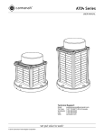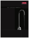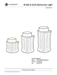
1
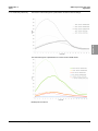
SAWL-High Intensity Solar
Light
Programming, Configuration and
Installation
User’s Manual
96A0444
66962 Rev A
Retain for future use.
Rev. A, 12/6/11
SAWL-High Intensity Solar Light
96A0444 Rev. A
12/6/11
Disclaimer
Disclaimer
Table of
Contents
This manual could contain technical inaccuracies or typographical errors. ADB Airfield Solutions reserves the right to
revise this manual from time to time in the contents thereof without obligation of ADB Airfield Solutions to notify any
person of such revision or change.
Details and values given in this manual have been compiled with care. They are not binding, however, and ADB
Airfield Solutions disclaims any liability for damages or detriments suffered as a result of reliance on the information
given herein or the use of products, processes or equipment to which this manual refers. No warranty is made that
the use of the information or of the products, processes or equipment to which this manual refers will not infringe any
third party's patents or rights.
Warranties
Safety
Products of ADB Airfield Solutions manufacturer are guaranteed against mechanical, electrical, and physical defects
(excluding lamps) for a period of one year from the date of installation or a maximum of 18 months from date of
shipment and are guaranteed to be merchantable and fit for the ordinary purposes for which such products are made.
ADB Airfield Solutions will correct by repair or replacement, at its option, equipment or parts which fail because of
mechanical, electrical or physical defects, provided that the goods have been properly handled and stored prior to
installation, properly installed and properly operated after installation, and provided further that Buyer gives ADB
Airfield Solutions written notice of such defects after delivery of the goods to Buyer. Refer to the Safety section for
more information on Material Handling Precautions and Storage precautions that must be followed.
ADB Airfield Solutions reserves the right to examine goods upon which a claim is made. Said goods must be
presented in the same condition as when the defect therein was discovered. ADB Airfield Solutions furthers reserves
the right to require the return of such goods to establish any claim.
ADB Airfield Solutions’ obligation under this guarantee is limited to making repair or replacement within a reasonable
time after receipt of such written notice and does not include any other costs such as the cost of removal of defective
part, installation of repaired product, labor or consequential damages of any kind, the exclusive remedy being to
require such new parts to be furnished.
ADB Airfield Solutions’ liability under no circumstances will exceed the contract price of goods claimed to be defective.
Any returns under this guarantee are to be on a transportation charges prepaid basis. For products not manufactured
by, but sold by ADB Airfield Solutions, warranty is limited to that extended by the original manufacturer.
This is ADB Airfield Solutions’ sole guarantee and warranty with respect to the goods; there are no express warranties
or warranties of fitness for any particular purpose or any implied warranties of fitness for any particular purpose or any
implied warranties other than those made expressly herein. All such warranties being expressly disclaimed.
Introduction Installation
Trademarks
General notice: other product names used here are for identification purposes only and may be trademarks of their
respective companies.
Proprietary Information
Operation
Parts
This information carrier contains proprietary information, which shall not be used for other purposes than those for
which it has been released, nor be reproduced or disclosed to third parties without the prior written consent of ADB
Airfield Solutions.
No part of this publication may be reproduced, stored in a retrieval system, or transmitted in any form or by any means,
mechanical, photocopy, recording, or otherwise, without the prior written permission of ADB Airfield Solutions. No
patent liability is assumed with respect to the use of the information contained herein. Neither is any liability assumed
for damages resulting from the use of the information contained herein.
ADB Airfield Solutions shall not be liable to the purchaser of this product or third parties for damages, losses, costs,
or expenses incurred by purchaser or third parties as a result of accident, misuse, or abuse of this product or
unauthorized modifications, repairs, or alterations to this product. ADB Airfield Solutions shall not be liable against
any damages arising from the use of any options or parts other than those designated as approved products.
Copyright © 2010 by ADB Airfield Solutions. All rights reserved.
Schematics
ii
© 2010 ADB Airfield Solutions All Rights Reserved
96A0444 Rev. A
12/6/11
SAWL-High Intensity Solar Light
Disclaimer
TABLE OF CONTENTS
1.0: Safety ................................................................................................................... 1
Table of
Contents
1.1 :To use this equipment safely: .............................................................................. 1
1.1.1 :Additional Reference Materials: .................................................................. 1
1.1.2 :Safety & Usage ............................................................................................ 1
1.1.3 :Viewing Precautions .................................................................................... 1
1.1.4 :Battery Precautions ..................................................................................... 2
1.1.5 :Wireless Precautions ................................................................................... 2
1.1.6 :Warranty Disclaimer .................................................................................... 2
2.0: SAWL-Hi............................................................................................................... 3
© 2010 ADB Airfield Solutions All Rights Reserved
Schematics
Parts
Operation
Installation Introduction
Safety
2.1 :About this manual ................................................................................................ 3
2.1.1 :How to work with the manual ....................................................................... 3
2.1.2 :Record of changes ...................................................................................... 3
2.1.3 :Icons used in the manual ............................................................................. 3
2.2 :Introduction .......................................................................................................... 4
2.2.1 :FCC Compliance ......................................................................................... 4
2.2.2 :Solar Aviation Wireless Light ....................................................................... 4
2.2.2.1 :Compliance with Standards ................................................................ 4
2.2.2.2 :Uses.................................................................................................... 4
2.2.2.3 :Features.............................................................................................. 5
2.2.3 :Wireless Hand-Held Controller .................................................................... 6
2.2.4 :Features ...................................................................................................... 6
2.2.5 :Spare Components ...................................................................................... 6
2.3 :Installation ............................................................................................................ 7
2.3.1 :Antenna ....................................................................................................... 8
2.3.2 :Location ....................................................................................................... 9
2.3.3 :Orientation ................................................................................................. 10
2.3.4 :Fastening ................................................................................................... 10
2.4 :Operation ........................................................................................................... 11
2.4.1 :Theory of Operation ................................................................................... 11
2.4.2 :User Interface ............................................................................................ 11
2.4.2.1 :Indicator LEDs .................................................................................. 11
2.4.2.2 :Push Button ..................................................................................... 12
2.4.3 :Modes ........................................................................................................ 14
2.4.3.1 :Autonomous Mode .......................................................................... 14
2.4.3.2 :Temporary Mode ............................................................................ 14
2.4.3.3 :Standby Mode ................................................................................. 15
2.4.3.4 :Lights Off Mode ............................................................................... 15
2.4.3.5 :Emergency Mode ............................................................................. 15
2.4.3.6 :ARCAL Mode ................................................................................... 15
2.4.3.7 :Storage Mode ................................................................................. 15
2.4.4 :Features .................................................................................................... 16
2.4.4.1 :Low Voltage Disconnect ................................................................... 16
2.4.4.2 :Automatic Light Control .................................................................... 16
2.4.4.3 :Low Voltage Disconnect ................................................................... 16
2.4.4.4 :External Power Operation................................................................. 16
2.4.4.5 :Battery Check ................................................................................... 17
2.4.4.6 :Flash Toggle ..................................................................................... 17
2.4.4.7 :Infrared Toggle ................................................................................. 17
2.4.4.8 :Push Button Lock Toggle.................................................................. 17
2.4.4.9 :Diagnose........................................................................................... 17
2.4.4.10 :Grouping ......................................................................................... 17
2.4.4.11 :Unique Code Sequence.................................................................. 17
2.4.4.12 :Factory Reset ................................................................................ 18
2.5 :Maintenance ....................................................................................................... 19
2.5.1 :Inspection .................................................................................................. 19
iii
SAWL-High Intensity Solar Light
96A0444 Rev. A
12/6/11
Disclaimer
2.5.2 :Storage & Battery Charging .......................................................................19
2.5.3 :Battery Replacement .................................................................................20
2.5.4 :Recycling ...................................................................................................25
2.6 :Troubleshooting ..................................................................................................26
2.7 :Appendices .........................................................................................................27
2.7.1 :Glossary .....................................................................................................27
2.7.2 :Autonomous Mode .....................................................................................27
2.7.3 :Temporary Mode Activations .....................................................................28
2.7.4 :Intensity .....................................................................................................30
2.7.4.1 :Preliminary values only ..................................................................... 31
2.8 :Specifications .....................................................................................................34
Table of
Contents
Safety
Introduction Installation
Operation
Parts
Schematics
iv
© 2010 ADB Airfield Solutions All Rights Reserved
96A0444 Rev. A
12/6/11
This section contains general safety instructions for installing and using ADB Airfield Solutions equipment. Some
safety instructions may not apply to the equipment in this manual. Task- and equipment-specific warnings are
included in other sections of this manual where appropriate.
1.1 To use this
equipment safely:
Disclaimer
1.0 Safety
SAWL-High Intensity Solar Light
Safety
WARNING
1.1.2 Safety & Usage
Safety
Installation Introduction
Safety
•
•
•
•
•
NFPA 70B, Electrical Equipment Maintenance.
NFPA 70E, Electrical Safety Requirements for Employee Workplaces.
ANSI/NFPA 79, Electrical Standards for Metalworking Machine Tools.
OSHA 29 CFR, Part 1910, Occupational Health and Safety Standards.
National and local electrical codes and standards.
Operation
1.1.1 Additional Reference
Materials:
Table of
Contents
Read installation instructions in their entirety before starting installation.
• Refer to the FAA Advisory Circular AC 150/5340-26, Maintenance of Airport Visual Aids Facilities, for
instructions on safety precautions.
• Observe all safety regulations. To avoid injuries, always disconnect power before making any wiring
connections or touching any parts. Refer to FAA Advisory Circular AC 150/5340-26.
• Become familiar with the general safety instructions in this section of the manual before installing,
operating, maintaining or repairing this equipment.
• Read and carefully follow the instructions throughout this manual for performing specific tasks and
working with specific equipment.
• Make this manual available to personnel installing, operating, maintaining or repairing this equipment.
• Follow all applicable safety procedures required by your company, industry standards and government
or other regulatory agencies.
• Install all electrical connections to local code.
• Use only electrical wire of sufficient gauge and insulation to handle the rated current demand. All wiring
must meet local codes.
• Route electrical wiring along a protected path. Make sure they will not be damaged by moving
equipment.
• Protect components from damage, wear, and harsh environment conditions.
• Allow ample room for maintenance, panel accessibility, and cover removal.
• Protect components from damage, wear, and harsh environment conditions.
• Allow ample room for maintenance, panel accessibility, and cover removal.
• Protect equipment with safety devices as specified by applicable safety regulations.
• If safety devices must be removed for installation, install them immediately after the work is completed
and check them for proper functioning prior to returning power to the circuit.
The following symbols indicate important safety warnings and precautions throughout this
manual:
Parts
WARNING indicates that serious bodily harm or death may result from
failure to adhere to the precautions.
Schematics
CAUTION indicates that damage to equipment may result if the instructions
are not followed.
NOTE suggests optimal conditions and provides additional information.
WIRELESS features and functions that require a Handheld Controller.
1.1.3 Viewing Precautions
© 2010 ADB Airfield Solutions All Rights Reserved
Do not view an actively emitting infrared or visible light from the side of the
light (close to or on beam) from a range of less than 4 ft. (1.2 m).
1
SAWL-High Intensity Solar Light
To use this equipment safely:
96A0444 Rev. A
12/6/11
Disclaimer
A safe limit for near-infrared viewing, established by the American Conference of
Governmental and Industrial Hygienists (ACGIH), is 65 mW/in2 (10 mW/cm2) as the
maximum exposure limit for viewing for up to 16 minutes. This power density can be
produced at the lens surface when actively emitting infrared light.
1.1.4 Battery Precautions
Table of
Contents
Use extreme caution when handling the light. This product is capable of
generating enormous short-circuit currents. Remove all jewelry (bracelets,
metal-strap watches, rings) before attempting to handle or remove the
batteries.
Charge your battery periodically. Permanent damage and reduced capacity
will result if the battery is not correctly maintained.
Safety
The rate of battery self-discharge is very dependent upon temperature. The warmer the
temperature, the faster the batteries will discharge.
Introduction Installation
To use this
equipment
Lights that have been stored will usually require a top-up charge before they are put into
service. The most accurate battery health status reading is obtained when the unit has been
in a dark location and in off mode for at least 24 hours.
1.1.5 Wireless Precautions
Keep the Handheld Controller at a distance of at least 3 ft. (1 m) from the
antennas of lights or other Handheld Controllers. It sends out a powerful
radio signal that could damage sensitive receiver circuitry if operated at
close range.
Regulatory
This device complies with Part 15 of the FCC Rules. Operation is subject to the following two
conditions:
1. This device may not cause harmful interference, and
Operation
2. This device must accept any interference received, including interference that may cause
undesired operation.
Parts
This equipment has been tested and found to comply with the limits for a Class B digital
device, pursuant to Part 15 of the FCC Rules. These limits are designed to provide
reasonable protection against harmful interference in a residential installation. This
equipment generates, uses, and can radiate radio frequency energy and, if not installed and
used in accordance with the instruction manual, may cause harmful interference to radio
communications; however, there is no guarantee that interference will not occur in a
particular installation. If this equipment does cause harmful interference to radio or television
reception, which can be determined by turning the equipment off or on, the user is
encouraged to try to correct the interference by one or more of the following measures:
Schematics
•
•
•
•
Reorient or relocate the receiving antenna;
Increase the separation between the equipment and receiver;
Connect the equipment into an outlet on a circuit different from that to which the receiver
is connected;
Consult the dealer or an experienced radio/TV technician for help.
This Class [B] digital apparatus complies with Canadian ICES-003.
Cet appareil numérique de la classe [B] est conforme à la norme NMB-003 du Canada.
1.1.6 Warranty Disclaimer
This manual will familiarize you with the features and operating standards
of the product. Failure to comply with the use, storage, maintenance, or
installation instructions detailed in this manual could void the user warranty.
Changes or modifications not expressly approved by the party responsible
for compliance could void the user’s authority to operate the equipment.
Installation work must be done by a qualified person(s) in accordance with
all application local codes and standards.
2
© 2010 ADB Airfield Solutions All Rights Reserved
SAWL-High Intensity Solar Light
SAWL-Hi
2.0 SAWL-Hi
SAWL-High Intensity (SAWL-Hi) Programming, Configuration and Installation.
2.1 About this manual
The manual shows the information necessary to:
•
Program and Configure SAWL-High Intensity Lights.
1. Become familiar with the structure and content.
2. Carry out the actions completely and in the given sequence.
Table of
Contents
2.1.1 How to work with the
manual
Disclaimer
96A0444 Rev. A
12/6/11
2.1.2 Record of changes
Rev
All
A
Description
Checked
Approved
Date
Released Manual
For all WARNING symbols see the Safety section.
Carefully read and observe all safety instructions in this manual, which alert you to safety
hazards and conditions that may result in personal injury, death or property and equipment
damage and are accompanied by the symbol shown below.
Installation
2.1.3 Icons used in the
manual
SAWL-Hi
Safety
Page
Operation
WARNING
• Failure to observe a warning may result in personal injury,
death or equipment damage.
CAUTION
Schematics
Parts
• Failure to observe a caution may result in equipment damage.
© 2010 ADB Airfield Solutions All Rights Reserved
3
SAWL-High Intensity Solar Light
Introduction
96A0444 Rev. A
12/6/11
Disclaimer
2.2 Introduction
This section describes the SAWL High Intensity fixture.
2.2.1 FCC Compliance
This device complies with Part 15 of the FCC Rules. Operation is subject to the following two
conditions: (1) This device may not cause harmful interference, and (2) this device must
accept any interference received, including interference that may cause undesired operation.
Table of
Contents
Changes or modifications not expressly approved by ADB Airfield Solutions, LLC could void
your authority to operate the equipment.
FCC Statement for Solar Aviation Wireless Light (SAWL) Light and Wireless Controller
Safety
This equipment has been tested and found to comply with the limits for a Class B digital
device, pursuant to Part 15 of the FCC Rules. These limits are designed to provide
reasonable protection against harmful interference in a residential installation. This
equipment generates, uses, and can radiate radio frequency energy and, if not installed and
used in accordance with the instruction manual, may cause harmful interference to radio
communications; however, there is no guarantee that interference will not occur in a
particular installation. If this equipment does cause harmful interference to radio or television
reception, which can be determined by turning the equipment off or on, the user is
encouraged to try to correct the interference by one or more of the following measures:
Introduction Installation
•
•
•
•
Reorient or relocate the receiving antenna
Increase the separation between the equipment and receiver
Connect the equipment into an outlet on a circuit different from that to which the receiver
is connected
Consult the dealer or an experienced radio/TV technician for help
FCC Statement for Non-wireless Solar Aviation Wireless Light (SAWL) Light
Operation
This equipment has been tested and found to comply with the limits for a Class A digital
device, pursuant to Part 15 of the FCC Rules. These limits are designed to provide
reasonable protection against harmful interference when the equipment is operated in a
commercial environment. This equipment generates, uses, and can radiate radio frequency
energy and, if not installed and used in accordance with the instruction manual, may cause
harmful interference to radio communications. Operation of this equipment in a residential
area is likely to cause harmful interference in which case you will be required to correct the
interference at your own expense.
2.2.2 Solar Aviation
Wireless Light
Parts
Solar LED Aviation and Obstruction Lights are certified to:
2.2.2.2 Uses
The SAWL High Intensity solar LED aviation light – designed for on-command performance in
extreme conditions – features an innovative combination of solar power, LEDs, and an
optional secure wireless control system. The control system allows for on-command
operation from ground or air over a range of up to 2.48 miles (4 km). Applications include:
Runway edge lighting – (ICAO Annex 14); portable or expedited airfield lighting; emergency
runway lighting; helipad lighting; and threshold lighting.
Schematics
2.2.2.1 Compliance with
Standards
4
CE, RoHS, ICAO, Explosive Atmosphere MILSTD-810G, Method 511.3
© 2010 ADB Airfield Solutions All Rights Reserved
Self-contained and low maintenance: all components are incorporated within a compact,
stand-alone unit. The SAWL also features a replaceable battery pack that extends the
service life beyond five years, reducing the total cost of ownership and resulting in
significant cost savings.
•
Unprecedented reliability: microprocessor Energy Management System (EMS) monitors
and adapts the brightness to environmental conditions for consistent operation and long
life under the toughest conditions.
•
User friendly: easy programming and operation options include push-button operation or
optional wireless control system offering secure 900 MHz wireless control from ground or
air. External 12 V service port allows for external charging or use of supplementary power
source.
•
Protect personnel and assets: Optional handheld wireless control allows for remote
operation of a SAWL airfield including mode changes for enhanced visibility in poor
weather conditions, or to blackout or infrared in response to immediate threat.
•
Meets tough industry standards: Certifications include ICAO and Explosive Atmosphere.
(NOTE: more detailed info to come).
•
Green solution: a clean, renewable and reliable energy source with the lightest
environmental footprint. The SAWL features recyclable batteries.
•
•
•
•
Six intensity level settings.
Dusk-to-dawn or on-command operation.
Programming options include push-button operation or optional wireless control system.
NVG-compatible IR option available with all color combinations.
Equipment Data
High-efficiency solar panels
Battery
Replaceable, recyclable best-in-class battery pack with extreme
temperature range. Battery status feedback via LEDs
Light Source
Ultra-bright LEDs feature innovative optic and lens design for optimum
light divergence.
Intensity
44.3 cd autonomous high mode. See photometric plot.
Flash Patterns
Steady-on only. User-programmed via onboard push-button switch or
optional handheld wireless controller.
Construction
Fully self-contained weather, corrosion and vandal-resistant unit with
premium-grade UV-resistant polycarbonate head.
Colors
LEDs: white, red, amber, blue, red/green split, amber/white split,
red/white split. All colors available with infrared CHASSIS: aviation
yellow, olive drab
Ambient Operating Temp.
-22 to 122° F (-30 to 50° C)
Storage Temperature
-40 to 176° F (-40 to 80° C)
Weight
26 lb (11.75 kg)
Automatic Light Control (ALC)
ALC dynamically reduces brightness in response to unusually low
amounts of sunlight to ensure continued operation
Radio Receiver
902-928 MHz FHSS
External Service Port
12V DC
© 2010 ADB Airfield Solutions All Rights Reserved
Parts
Solar Panel
Operation
Table 1:
Disclaimer
•
Table of
Contents
Easy installation and relocation: no specialized work crew required, limited air traffic
disruption, and lights are immediately operational. Featuring a built-in handle, the SAWL
can be quickly relocated for temporary or emergency applications. Multiple mounting
options allow for three or four-bolt mounting patterns.
Safety
•
Schematics
2.2.2.3 Features
SAWL-High Intensity Solar Light
Introduction
Installation Introduction
96A0444 Rev. A
12/6/11
5
SAWL-High Intensity Solar Light
Introduction
Disclaimer
2.2.3 Wireless Hand-Held
Controller
96A0444 Rev. A
12/6/11
One or more wireless SAWL-Hi lights can be remotely operated from the ground or air with a
handheld wireless controller: secure radio transceiver, with antenna and keypad.
Table of
Contents
Wireless Hand-Held Controller
Ordering Code
Part # SAWL-HC
Battery Replacement Kit for
Wireless Hand-held Controller
Safety
2.2.4 Features
Introduction Installation
2.2.5 Spare Components
•
•
•
•
•
•
•
•
Part # 48247
Water-resistant keypad and LED indicators.
Utilizes a secure wireless RF signal.
Control range of up to 2.5 miles.
Meets MIL-SPEC-810E environmental requirements.
24-hour operation on a single charge.
Rechargeable lithium-ion battery (included); recharges via an AC/DC wall plug (included).
Compatible with stand-alone aviation band VHF receiver.
Comes complete in a custom Pelican™ case.
For a complete list of solar aviation light accessories, including mounting equipment, see
Catalog Sheet 3017.
Operation
Parts
Schematics
6
© 2010 ADB Airfield Solutions All Rights Reserved
96A0444 Rev. A
12/6/11
The SAWL-Hi includes:
SAWL-Hi
Antenna (Wireless Only)
Quick Start Guide
Installation
Installation
Safety
Table of
Contents
•
•
•
Disclaimer
2.3 Installation
SAWL-High Intensity Solar Light
Installation
Schematics
Parts
Operation
The manual (this document) is shipped independently. It is available for download from
www.adb-airfield.com
© 2010 ADB Airfield Solutions All Rights Reserved
7
SAWL-High Intensity Solar Light
Installation
Disclaimer
2.3.1 Antenna
96A0444 Rev. A
12/6/11
Only the SAWL-Hi with optional wireless control includes an antenna. Grip the antenna by its
metal base and hand-tighten it onto the antenna connector.
Table of
Contents
Safety
Installation
Installation
The effective range of the wireless control system is 2.5 miles (4 km). Wireless range is
greatly affected by use and location. To achieve the best wireless range:
Operation
— Handheld Controller antenna is parallel to the light’s antenna
Parts
Schematics
— Elevate the Handheld Controller’s antenna
— Ensure surrounding grass and foliage is trim
— Clear line-of-sight between antennas
8
© 2010 ADB Airfield Solutions All Rights Reserved
SAWL-High Intensity Solar Light
Installation
Disclaimer
2.3.2 Location
Year-round, unrestricted solar exposure is critical to long-term
performance.
Shade dramatically reduces the ability of the light to charge its battery.
Cooler is better: The battery lasts longest if you can minimize its exposure to high
temperatures. Choose a location that is away from hot, dark colored surfaces like asphalt or
black steel plate. Mounting kits are available that elevate the light and can help reduce the
temperature of the battery.
Schematics
Parts
Flat: Ensure the mounting surface is flat and level. .
Operation
Installation
Installation
Safety
Year-round sun: During the winter, the sun is lower on the horizon. Because the angle of
the sun changes with the seasons, you must be aware that obstructions such as trees,
buildings, and mountains that do not shade the solar panel during the summer may shade it
during the winter.
Table of
Contents
96A0444 Rev. A
12/6/11
© 2010 ADB Airfield Solutions All Rights Reserved
9
SAWL-High Intensity Solar Light
Installation
Disclaimer
2.3.3 Orientation
96A0444 Rev. A
12/6/11
The handle can be used to orient the light relative to the runway. This is useful for directional
and bidirectional lights:
Red / Green
directional
Table of
Contents
White omnidirectional
Safety
2.3.4 Fastening
White directional
The SAWL-Hi can be mounted using 0.5 in. (12 mm) fasteners. The mounting holes have a
bolt circle of 7.87 in. (200 mm). Fasteners are not included but are available as kits.
Installation
Installation
Operation
Parts
Schematics
10
© 2010 ADB Airfield Solutions All Rights Reserved
During daylight, the solar panels charge the battery using the Energy Management
System (EMS). The capacity of the battery ensures that even with poor levels of
sunlight over an extended period, the light has enough reserve power to continue to
perform reliably.
Stored battery energy is then available to power the output LEDs in one of several
modes. These modes are selected using the push button user interface on the light
or a Handheld Controller. The most commonly used modes are Autonomous and
Temporary Modes.
The Handheld Controller contains a 900 MHz radio that transmits commands to a
receiving radio inside the SAWL-Hi. For Handheld Controller operation and button
sequences, see its manual.
2.4.2 User Interface
2.4.2.1 Indicator LEDs
Inside the lens, near the push button, are three indicator LEDs that illuminate green, amber or
red. They:
— Guide push button operation
— Indicate diagnostic feedback
— Indicate normal operating state after the push button has not been used for 10 sec.:
All indicators are off
Operating State
Installation
Indicator
Autonomous or Temporary Mode, Infrared LED
output
Amber indicator LED flashes 1x every 1 sec.
Battery is charging via the external power
connector
Amber indicator LED flashes 1x every 2 sec.
Battery is charging via the solar panels
Schematics
Parts
Autonomous or Temporary Mode, Visible LED
output
Operation
Storage Mode
Green indicator LED flashes 1x every 2 sec.
Table of
Contents
2.4.1 Theory of Operation
Safety
2.4 Operation
Disclaimer
SAWL-High Intensity Solar Light
Operation
Operation
96A0444 Rev. A
12/6/11
© 2010 ADB Airfield Solutions All Rights Reserved
11
SAWL-High Intensity Solar Light
Operation
Disclaimer
2.4.2.2 Push Button
96A0444 Rev. A
12/6/11
The push button on the light is used for configuration and control.
Table of
Contents
Safety
Operation
It can be used in conjunction with, or instead of, a Handheld Controller for most modes and
features.
The two types of push button inputs are:
Installation
Pressing and holding the push button down for several sec. will cycle through the
command levels
Hold
The command level is indicated by the number of amber indicator LED flashes
Once the desired command level has been reached, release the push button
Momentarily pressing the push button 1x – 5x chooses a command within that
command level
Operation
Each momentary press must be quick and less than 1 sec.
Press
You must select a command within 10 sec. of entering a command level, otherwise
the light exits that command level
The green indicator LED flashes the number of accepted momentary presses
The red indicator LED flashes three times if the command has not been accepted
Parts
Indicator LED and push button sequences will be referred to as:
[hold push button for # amber indicator LED flashes, press push button #]
For example, [4,2] is:
Schematics
1. Press and hold the push button until amber indicator LED flashes quickly 4x
2. Quickly press the push button 2x, green indicator LED flashes quickly 2x
12
© 2010 ADB Airfield Solutions All Rights Reserved
SAWL-High Intensity Solar Light
Operation
The following are all available push button commands:
Step 2:
Choose Command
No hold
(0 amber flashes)
0
2 sec. hold
(1 amber flash)
1
4 sec. hold
(2 amber flashes)
2
6 sec. hold
(3 amber flashes)
3
8 sec. hold
(4 amber flashes)
4
10 sec. hold
(5 amber flashes)
5
1 press
(1 green flash)
2 presses
(2 green flashes)
3 presses
(3 green flashes)
4 presses
(4 green flashes)
5 presses
(5 green flashes)
Standby Mode
Autonomous Low
Autonomous Med
Autonomous High
Flash Toggle
[0,4]
[0,5]
No action
No action
[0,1]
[0,2]
[0,3]
Temporary Low
Temporary Med
Temporary High
[1,1]
[1,2]
[1,3]
Do Not Use*
Do Not Use*
No action
No action
No action
No action
No action
No action
No action
No action
No action
No action
No action
Storage Mode
[2,1]
Infrared Toggle
[3,1]
Battery Check
UCS Status
[4,1]
[4,2]
No action
Button Lock Toggle
[5,2]
Table of
Contents
Command
Level
Safety
Action
(Response)
Operation
Step 1:
Choose Command Level
Disclaimer
96A0444 Rev. A
12/6/11
Factory Reset
[5,5]
Schematics
Parts
Operation
Installation
* For engineering test purposes only. Use may result in unpredictable behavior of
the light.
© 2010 ADB Airfield Solutions All Rights Reserved
13
SAWL-High Intensity Solar Light
Operation
96A0444 Rev. A
12/6/11
Disclaimer
2.4.3 Modes
2.4.3.1 Autonomous Mode
In Autonomous Mode, the output LEDs turn on during the night and turn off during the day.
The change from day-to-night or night-to-day is known as a transition. A built-in ambient
brightness sensor detects transitions.
NOTE: Autonomous Mode setting is determined by a map in the Appendices.
Correct setting is important to ensure sustainable, year-round operation.
Table of
Contents
The Autonomous Mode setting is selected by push button sequence [0,2], [0,3], [0.4] or the
Handheld Controller:
Setting
Auto Low
Intensity
Output LEDs
Flashing
Active
Dusk-to-dawn
Safety
Operation
Installation
Low
Visible
No
AUTO MED
Medium
Visible
No
Dusk-to-dawn
AUTO HIGH
High
Visible
No
Dusk-to-dawn
Auto Low IR
Low
Infrared
No
Dusk-to-dawn
AUTO MED IR
Medium
Infrared
No
Dusk-to-dawn
AUTO HIGH IR
High
Infrared
No
Dusk-to-dawn
Auto Low flash
Low
Visible
0.25 sec. on, 0.75 sec. off
Dusk-to-dawn
AUTO MED flash
Medium
Visible
0.25 sec. on, 0.75 sec. off
Dusk-to-dawn
AUTO HIGH flash
High
Visible
0.25 sec. on, 0.75 sec. off
Dusk-to-dawn
Auto Low IR flash
Low
Infrared
0.25 sec. on, 0.75 sec. off
Dusk-to-dawn
AUTO MED IR flash
Medium
Infrared
0.25 sec. on, 0.75 sec. off
Dusk-to-dawn
AUTO HIGH IR flash
High
Infrared
0.25 sec. on, 0.75 sec. off
Dusk-to-dawn
Factory default is AUTO LOW, visible LED, steady-on.
2.4.3.2 Temporary Mode
A Temporary Mode activation interrupts other modes and ignores transitions. This activation
lasts for a preset time and then the light reverts to its previous Autonomous Mode.
Operation
NOTE: Maximum number of Temporary Mode activations per day is determined by a map in
the Appendices.
The Temporary Mode setting is selected by push button sequence [1,1], [1,2], [1,3], or the
Handheld Controller:
Parts
Setting
Schematics
14
Intensity
Output LEDs
Activation,
Handheld
Controller
command
Flashing
Activation, push
button
command
temp Low
Low
Visible
No
15 min.
60 min.
TEMP MED
Medium
Visible
No
15 min.
60 min.
60 min.
TEMP HIGH
High
Visible
No
15 min.
temp Low IR
Low
Infrared
No
15 min.
60 min.
temp MED IR
Medium
Infrared
No
15 min.
60 min.
temp HIGH IR
High
Infrared
No
15 min.
60 min.
60 min.
temp Low flash
Low
Visible
0.25 sec. on, 0.75 sec. off
15 min.
temp MED flash
Medium
Visible
0.25 sec. on, 0.75 sec. off
15 min.
60 min.
temp HIGH flash
High
Visible
0.25 sec. on, 0.75 sec. off
15 min.
60 min.
temp Low IR flash
Low
Infrared
0.25 sec. on, 0.75 sec. off
15 min.
60 min.
temp MED IR flash
Medium
Infrared
0.25 sec. on, 0.75 sec. off
15 min.
60 min.
temp HIGH IR flash
High
Infrared
0.25 sec. on, 0.75 sec. off
15 min.
60 min.
© 2010 ADB Airfield Solutions All Rights Reserved
2.4.3.4 Lights Off Mode
Lights Off Mode turns off the output LEDs indefinitely until it receives a command to turn them
on.
Lights Off Mode is enabled by the Handheld Controller.
2.4.3.5 Emergency Mode
Emergency Mode sets all lights in all groups to emergency flash. Emergency flash is TEMP
HIGH FLASH. After 15 min., the lights revert to their previous Autonomous modes.
Emergency Mode is enabled by the Handheld Controller.
2.4.3.6 ARCAL Mode
The Aircraft Radio Control of Aerodrome Lighting (ARCAL) feature works in conjunction with
an ARCAL VHF receiver to allow aircraft pilots to control the airfield lights.
ARCAL Mode is enabled by the Handheld Controller.
Storage Mode is a low power state used for storing or shipping the light. Lights are shipped
from the factory in Storage Mode:
Operation
2.4.3.7 Storage Mode
Disclaimer
Standby Mode is enabled by push button sequence [0,1] or the Handheld Controller.
Table of
Contents
Standby Mode turns off the output LEDs and waits for the next day-to-night transition. After
this transition, the light enters its previous Autonomous Mode.
— No response to wireless control and not able to turn on its output LEDs
— Indicator LEDs are off
— Stores the last mode before entering Storage Mode
— Sunlight or external power will continue to charge the battery
NOTE: If the ambient light level is 30 lux or less for 24 hrs., the light will automatically enable
Storage Mode
Storage Mode is enabled by push button sequence [2,1] or the Handheld Controller.
Schematics
Parts
Operation
To disable Storage Mode, press the push button 1x.
Installation
2.4.3.3 Standby Mode
SAWL-High Intensity Solar Light
Operation
Safety
96A0444 Rev. A
12/6/11
© 2010 ADB Airfield Solutions All Rights Reserved
15
SAWL-High Intensity Solar Light
Operation
96A0444 Rev. A
12/6/11
Disclaimer
2.4.4 Features
2.4.4.1 Low Voltage Disconnect
Low Voltage Disconnect (LVD) protects the battery from being discharged to levels low
enough to cause permanent damage. When LVD is entered:
— "Radio and output LEDs are disabled
— "Output LEDs flashes 0.1 sec. every 60 sec. to let the user know the light needs
attention
Table of
Contents
— "Red indicator LED is flashing
— "Battery continues charging
— "When the battery state of charge reaches an acceptable level, LVD is exited.
LVD is enabled in all modes.
Safety
2.4.4.2 Automatic Light Control
Automatic Light Control (ALC) is a patented algorithm that matches the light's energy
consumption to its energy storage. As the battery state of charge diminishes, ALC decreases
the output LED intensity. ALC has 4 intensity steps until finally entering LVD. The ALC step
depends on the battery state of charge. This ensures the light will continue to operate
through periods of poor sunlight.
Operation
ALC is enabled in all Autonomous Modes.
ALC is disabled in all Temporary Modes.
2.4.4.3 Low Voltage Disconnect
Low Voltage Disconnect (LVD) protects the battery from being discharged to levels low
enough to cause permanent damage. When LVD is entered:
Installation
— Radio and output LEDs are disabled
— Output LEDs flashes 0.1 sec. every 60 sec. to let the user know the light needs
attention
— Red indicator LED is flashing
— Battery continues charging
Operation
— When the battery state of charge reaches an acceptable level, LVD is exited.
LVD is enabled in all modes.
2.4.4.4 External Power
Operation
If continuous high intensity output or backup power is required, external power can be
provided to the connector on the base plate:
Remove the connector cap and attach a power cable terminated with the correct mating
connector and pinout:
Parts
— "MS3116 connector detailed in MIL-DTL-26482 (approved vendor: Amphenol PT06-E8-3P-SR-025)
— "Connector accepts 24 - 20 AWG stranded wire
Schematics
— "+9.0 to 13.5 VDC input @ 2.2 A max.
When connected, external power is used to power up the light and charge its battery.
External power is not a control signal and cannot configure the light. The push button or
Handheld Controller is still used for normal operations.
— When external power is provided to the connector on the base plate, the light will not
exit Temporary Mode after a preset time.
It will remain in Temporary Mode until commanded otherwise or until the light detects that
external power is no longer available.
16
© 2010 ADB Airfield Solutions All Rights Reserved
96A0444 Rev. A
12/6/11
Battery State of Charge
Green
Good, 75 - 100%
Amber
Charge, 50 - 75%
Red
LVD, 5 - 50%
Flashing Red
LVD, < 5%
2.4.4.6 Flash Toggle
Push button sequence [0,5] toggles between steady-on and flashing output LEDs.
2.4.4.7 Infrared Toggle
Push button sequence [3,1] toggles between visible and infrared output LEDs.
— Push button sequence [5,2] toggles between locking and unlocking the push button:
— "Red indicator LED flashes 2x when the push button is first locked
— "When locked, push button commands are ignored
— "If any other push button command is given other than unlocking the push button, the
red indicator LED flashes 3x
— "Green indicator LED flashes 2x when the push button is unlocked
2.4.4.9 Diagnose
The battery state of charge and radio health can be queried via the Handheld Controller using
its Diagnose function.
Diagnose is disabled when LVD is entered.
Grouping allows independent control of different subsets of lights on an airfield:
Installation
2.4.4.10 Grouping
Safety
2.4.4.8 Push Button Lock
Toggle
Table of
Contents
Indicator
Disclaimer
Push button sequence [4,1] checks the battery state of charge. The indicator LEDs then
show the following for 10 sec.:
Operation
2.4.4.5 Battery Check
SAWL-High Intensity Solar Light
Operation
— There are 8 groups, numbered 1 through 8
— Each light can be assigned to only one group
— Handheld controller can control multiple groups at a time
Operation
— A light can be reassigned to another group as required
— When adding a light to a group, the Handheld Controller re-sends the last mode to
everyone in that group
In order to configure the group of a light:
1. Light must be powered for at least 10 sec. and not in Storage Mode
Parts
2. Press the push button 1x. This instructs the light to receive grouping configurations from
the Handheld Controller for 5 min.
3. Grouping configuration is sent from Handheld Controller
4. After successfully receiving a grouping configuration, the
Factory default is group 1.
2.4.4.11 Unique Code
Sequence
Unique Code Sequence (UCS) allows one or more Handheld Controllers to be uniquely
associated to one or more lights. When UCS is enabled, the Handheld Controller sends a
code with each radio transmission. Only lights configured to accept that particular code will
respond to the transmission. The benefits are:
Independence
Nearby installations of lights can be operated independently by different
Handheld Controllers without interference
Security
It is not possible for another Handheld Controller to interrupt airfield
operation
The Handheld Controller cannot control UCS configured and non-UCS configured lights at
the same time.
For security, the user has to manually interact with the light for UCS configuration:
1. Light must be on for at least 10 sec. and not in Storage Mode
2. Press the push button 1x. This instructs the light to receive UCS configurations from the
Handheld Controller for 5 min.
© 2010 ADB Airfield Solutions All Rights Reserved
17
Schematics
5. light receives that group’s last mode from the Handheld Controller.
SAWL-High Intensity Solar Light
Operation
96A0444 Rev. A
12/6/11
Disclaimer
3. UCS configuration is sent from Handheld Controller
4. After successfully receiving a UCS configuration, the light flashes for 5 sec.
Push button sequence [4,2] requests the UCS status from the indicator LEDs:
Table of
Contents
Indicator
UCS
Amber
Enabled
Red
Disabled
Factory default is UCS disabled.
2.4.4.12 Factory Reset
Push button sequence [5,5] performs a Factory Reset that sets the light back to a known
state:
Safety
— AUTO LOW visible LED, steady-on
— Group 1
— UCS off
Green, amber, and red indicator LEDs momentarily turn on, then turn off once the reset is
complete
Operation
Installation
Operation
Parts
Schematics
18
© 2010 ADB Airfield Solutions All Rights Reserved
2.5 Maintenance
2.5.1 Inspection
Although the SAWL-Hi is maintenance-free, significant performance gains can be made with
clean solar panels and lenses:
— Clean the solar panels monthly. Use water and a soft sponge or cloth. A mild nonabrasive cleanser can be used for more stubborn residue. Rinse well.
— Clean solar panels and lenses more frequently during drier months, as they may
become covered in dust more quickly. A pressure washer is not recommended.
— Visual inspection – check the exterior for cracks, missing or broken hardware or other
potential problems.
When storing the light, it is important to maintain the battery:
— Put the light in Storage Mode or disconnect the battery
Safety
2.5.2 Storage & Battery
Charging
Disclaimer
SAWL-High Intensity Solar Light
Maintenance
Table of
Contents
96A0444 Rev. A
12/6/11
— Store in a cool location
— Check the battery state of charge every 1 month
Maintenance
NOTE: Do not use the Lights Off Mode for storing the light. The radio is still active in this
mode and may receive wireless commands.
If charging is required, charge the battery fully using one of several methods:
12 in. (30 cm) from solar panels
Halogen light bulb, 500 W
24 in. (60 cm) from solar panels
Installation
Incandescent light bulb, 60 W
Time to Charge
from 10% to 100%
State of Charge
>1000 hrs.
600 hrs.
150 hrs.
Available AC plug-in charger attached to the connector on the
base plate
18 hrs.
Schematics
Parts
Direct sunlight
Operation
Source
© 2010 ADB Airfield Solutions All Rights Reserved
19
SAWL-High Intensity Solar Light
Maintenance
Disclaimer
2.5.3 Battery Replacement
96A0444 Rev. A
12/6/11
NOTE: The SAWL-Hi and the SAWL battery packs are not interchangeable.
Contact your distributor for your specific replacement battery pack.
If the battery is permanently damaged and needs to be replaced:
1. Remove the 4 base plate screws using a 5/32 in. hex driver; be careful not to misplace
their o-rings
Table of
Contents
Safety
Maintenance
Installation
Operation
Parts
Schematics
2. Pull on the handle to slowly separate the chassis from the base plate
Use extreme caution with the metal chassis near the exposed
battery terminals.
20
© 2010 ADB Airfield Solutions All Rights Reserved
SAWL-High Intensity Solar Light
Maintenance
Schematics
Parts
Operation
Installation
Maintenance
Safety
Table of
Contents
Disclaimer
96A0444 Rev. A
12/6/11
3. Disconnect the battery harness and remove the chassis
© 2010 ADB Airfield Solutions All Rights Reserved
21
SAWL-High Intensity Solar Light
Maintenance
96A0444 Rev. A
12/6/11
Disclaimer
Table of
Contents
Safety
Maintenance
Installation
Operation
Parts
4. Disconnect the external power harness and remove from routing features
Schematics
22
© 2010 ADB Airfield Solutions All Rights Reserved
96A0444 Rev. A
12/6/11
SAWL-High Intensity Solar Light
Maintenance
Disclaimer
5. Using a ½ in. hex socket, remove only the central bolt and its hardware
Schematics
Parts
Operation
Installation
Maintenance
Safety
Table of
Contents
Use extreme caution near the exposed battery terminals with
metal tools. Remove all jewelry before attempting to handle
or remove the batteries.
6. Pull the battery up and over its mounting post
© 2010 ADB Airfield Solutions All Rights Reserved
23
SAWL-High Intensity Solar Light
Maintenance
96A0444 Rev. A
12/6/11
Disclaimer
Table of
Contents
Safety
Installing a battery is similar to the above steps:
Maintenance
1. Carefully slide the battery over the mounting post, noting the correct orientation of the
battery to the external power harness
2. Ensure the individual batteries are tight together and inside the base plate gasket.
Tighten the central bolt and its hardware to 200 in.-lbs.
Installation
3. Connect the external power harness and attach it to its routing features
4. Ensure the base plate gasket is clean and seated in its groove
5. Hold the chassis over the battery and connect the battery harness
6. Align the handle with the connector on the base plate and slowly slide the chassis over
the battery.
Operation
Parts
Schematics
7. Press base plate screw o-rings into their counterbores. Tighten 4 base plate screws to
105 in.-lbs.
24
© 2010 ADB Airfield Solutions All Rights Reserved
This product required the extraction and use of natural resources. It may contain substances
that could be harmful to the environment or human health if improperly handled at the
product’s end of life. In order to avoid release of such substances into the environment and
to reduce the use of natural resources, we encourage you to recycle the product in an
appropriate way that will ensure most of the materials are reused or recycled appropriately.
Check your local municipality for electronics recyclers.
Maintenance
NOTE: The symbol indicates that this product complies with the European Union’s
requirements according to Directive 2002/96/EC on waste electrical and electronic equipment
(WEEE).
Safety
Table of
Contents
2.5.4 Recycling
SAWL-High Intensity Solar Light
Maintenance
Disclaimer
96A0444 Rev. A
12/6/11
Schematics
Parts
Operation
Installation
NOTE: The battery is a rechargeable lead-acid AGM battery. Consult your local laws for
information on recycling.
© 2010 ADB Airfield Solutions All Rights Reserved
25
SAWL-High Intensity Solar Light
Troubleshooting
96A0444 Rev. A
12/6/11
Disclaimer
2.6 Troubleshooting
Symptom
Feedback
Cause
Infrared output LEDs are on
Table of
Contents
Output LEDs are off
All indicator LEDs are off
Unresponsive to wireless
control
Solution
De-select the IR button on the Handheld
Controller and send a visible output
command;
Use push button infrared toggle [3,1]
Storage Mode is active
Output LEDs flash once every
60 sec;
LVD is entered
De-activate Storage Mode by pressing push
button 1x
Charge the battery
Red indicator LED is flashing
Safety
Output LEDs are on or off
Troubleshooting
Unresponsive to wireless
control
Green indicator LED is
flashing;
Output LEDs are off
Installation
Unresponsive to wireless
control
All indicator LEDs are off
Mismatched groups
Ensure the Handheld Controller’s and light’s
group match
UCS is enabled
Ensure the Handheld Controller’s and light’s
UCS match or turn off UCS
Antenna not installed
Ensure the light’s antenna is properly
installed
Handheld Controller problem
Check Handheld Controller battery, PIN
status, and Passthrough
Battery is bad
Replace the battery
Battery is not connected
Check that the battery connector is fully
inserted
Unresponsive to push
button
All indicator LEDs are off
Infrared output LEDs are on
De-select the IR button on the Handheld
Controller and send a visible output
command;
Operation
Use push button infrared toggle [3,1]
Output LEDs are off in
Autonomous Mode
Green indicator LED is
flashing
Daylight; ambient brightness is
above 500 lux
Darken the entire light and wait 20 sec. for
the light to turn on
Nearby lights are illuminating the
ambient brightness sensor
Increase distance between lights, turn off
unneeded lights, or shield lights
Parts
Schematics
26
© 2010 ADB Airfield Solutions All Rights Reserved
SAWL-High Intensity Solar Light
Appendices
Disclaimer
2.7 Appendices
2.7.1 Glossary
American Conference of Governmental and Industrial Hygienists
AGM
Absorbed Glass Matt
Automatic Light Control
ARCAL
Aircraft Radio Control of Aerodrome Lighting
DC
Direct Current
EMS
Energy Management System
FAA
Federal Aviation Administration
FCC
Federal Communications Commission
ICAO
International Civil Aviation Organization
ICES
Industry Canada Equipment Standard
IR
Infrared
ISM
Industrial, Scientific and Medical
LED
Light Emitting Diode
LVD
Low Voltage Disconnect
NVG
Night Vision Goggle
OBUI
On-Board User Interface
RoHS
Restriction on Hazardous Substances
UCS
Universal Code Sequence
WEEE
Waste Electrical and Electronic Equipment
Safety
ALC
Table of
Contents
Alternating Current
ACGIH
The recommended Autonomous Mode setting is determined by the amount of solar energy,
day length, and ambient temperature at a given location. The below table and plot are based
on:
— "Autonomous Mode operates dusk-to-dawn
— "No Temporary Mode activations
— "Worst Month of the year
Installation Appendices
2.7.2 Autonomous Mode
AC
Operation
96A0444 Rev. A
12/6/11
— "Infrared output LEDs consume less energy than the visible output LEDs
Parts
— "Flashing consumes less energy since the LEDs are on for less time
Schematics
Autonomy is the number of days that the light can operate without any solar energy. It is
determined by the Autonomous Mode, day length, and the battery size. Several days of
autonomy is required to ensure continued functionality during periods of poor weather.
Autonomous Mode Settings
Blue Region
Yellow Region
Red Region
AUTO LOW
AUTO MED
AUTO HIGH
AUTO HIGH FLASH
AUTO HIGH FLASH
AUTO HIGH FLASH
AUTO MED IR
AUTO HIGH IR
AUTO HIGH IR
AUTO HIGH IR FLASH
AUTO HIGH IR FLASH
AUTO HIGH IR FLASH
14 days min. autonomy
11 days min. autonomy
8 days min. autonomy
© 2010 ADB Airfield Solutions All Rights Reserved
Grey Region
Not
recommended
for installation
27
SAWL-High Intensity Solar Light
Appendices
96A0444 Rev. A
12/6/11
Disclaimer
Figure 1:
Table of
Contents
Safety
Appendices Installation
2.7.3 Temporary Mode
Activations
The maximum number of Temporary Mode activations per day is determined by the amount
of solar energy and ambient temperature at a given location. The below table and plot are
based on:
— "Handheld Controller commands with a 15 min. activation time
Operation
— "Light is in Lights Off Mode when not in a Temporary Mode activation
— "Worst month of the year
— "Infrared output LEDs consume less energy than the visible output LEDs
— "Flashing consumes less energy since the LEDs are on for less time
NOTE: It is possible to use more Temporary Mode activations per day. The battery will then
require more than 1 day of solar energy to fully charge.
Parts
Temporary Mode Activations, daily max.
Schematics
Setting
Blue Region
Yellow Region
Red Region
temp Low
4
13
22
16
TEMP MED
3
10
TEMP HIGH
2
6
10
temp Low IR
73
96
96
temp MED IR
43
96
96
temp HIGH IR
21
64
96
temp Low flash
16
49
81
temp MED flash
12
36
61
temp HIGH flash
8
23
39
temp Low IR flash
96
96
96
temp MED IR flash
96
96
96
temp HIGH IR flash
63
96
96
Grey Region
Not recommended
for installation
* 96 activations = 24 hrs. is the theoretical daily max.
28
© 2010 ADB Airfield Solutions All Rights Reserved
SAWL-High Intensity Solar Light
Appendices
Schematics
Parts
Operation
Installation Appendices
Safety
Table of
Contents
Disclaimer
96A0444 Rev. A
12/6/11
© 2010 ADB Airfield Solutions All Rights Reserved
29
SAWL-High Intensity Solar Light
Appendices
Disclaimer
2.7.4 Intensity
96A0444 Rev. A
12/6/11
The minimum peak intensity for all modes and colors is below:
— "Visible output unit is candela (cd)
— "Infrared output unit is milliwatts per steradian (mW/sr) at 870 nm peak wavelength
— ""Directional" is a focused output beam
Table of
Contents
— ""Omnidirectional" is 360° output; when "Directional" is active, "Omnidirectional" is
also active
— ""Bidirectional" is 180° output from one side of the light and 180° output from the other
side
— ""Unidirectional" is 180° output only
Safety
Peak Intensity, min.
AUTO LOW
or
AUTO LOW
FLASH
AUTO MED
or
AUTO MED
FLASH
AUTO HIGH
or
AUTO HIGH
FLASH
TEMP LOW
or
TEMP LOW
FLASH
TEMP MED
or
TEMP MED
FLASH
TEMP HIGH
or
TEMP HIGH
FLASH
18
45
74
160
160
160
directional
-
-
-
-
248
504
Blue
omnidirectional
6
7
17
6
7
17
Red
omnidirectional
15
48
73
15
48
73
Yellow
omnidirectional
4*
10*
16*
40*
61*
81*
Green
omnidirectional
14
36
59
154
237
316
Red /
Green
red directional
17
17
17
28
48
68
green directional
44
109
179
320
415
557
yellow bidirectional
13*
32*
52*
112*
112*
112*
yellow directional
-
-
-
-
174*
353*
white bidirectional
18
45
74
160
160
160
white directional
-
-
-
-
248
504
red bidirectional
9*
23*
37*
80*
80*
80*
-
-
-
-
124*
252*
18
45
74
160
160
160
white directional
-
-
-
-
248
504
omnidirectional
14
31
74
14
31
74
Output
Direction
Appendices Installation
omnidirectional
White
Operation
Yellow /
White
Parts
red directional
Red / White
Schematics
white bidirectional
Infrared
30
© 2010 ADB Airfield Solutions All Rights Reserved
96A0444 Rev. A
12/6/11
Disclaimer
The minimum vertical divergence is plotted below for white at various settings:
Installation Appendices
Safety
Table of
Contents
2.7.4.1 Preliminary values only
SAWL-High Intensity Solar Light
Appendices
Schematics
Parts
Operation
The vertical divergence is plotted below for various colors at TEMP HIGH:
Detailed plot of the above:
© 2010 ADB Airfield Solutions All Rights Reserved
31
SAWL-High Intensity Solar Light
Appendices
96A0444 Rev. A
12/6/11
Disclaimer
Table of
Contents
Safety
Appendices Installation
A representative horizontal intensity plot is below:
Operation
Parts
Schematics
The light's handle is in the right-hand position on this plot and the units are cd. This shows
that the red/green directional output is 90° to the white output with respect to the handle.
NOTE: White output changes from omnidirectional in AUTO LOW, AUTO MED, AUTO HIGH,
and TEMP LOW settings to omnidirectional plus directional in the TEMP MED and TEMP
HIGH settings.
32
© 2010 ADB Airfield Solutions All Rights Reserved
96A0444 Rev. A
12/6/11
SAWL-High Intensity Solar Light
Appendices
Disclaimer
The following are minimum recommended intensity settings to achieve a photometric
specification. Higher intensity settings can be used, depending on the specification.
Photometric Specifications Met
Output
AUTO LOW
AUTO MED
AUTO HIGH
TEMP LOW
TEMP MED
TEMP HIGH
Table of
Contents
L-863W
L-860
ICAO
ICAO
runway 25 cd
White
L-861
step 1 of 3
step 2 of 3
runway 50 cd
L-861
step 3 of 3
L-862
Safety
L-861
L-862
step 1
of 5
step 2 of 5
L-863B
taxiway
edge1
ICAO taxiway
edge1
L-861T1
Installation Appendices
Blue
ICAO
L-861T1
L-863R
Red
ICAO Obs.
ICAO Obs.
ICAO Obs.
ICAO Obs.
Type A 10 cd
Type B 32 cd
Type A 10 cd
Type B 32 cd
L-810
L-810
L-860E
L-860E
L-863Y*
Yellow
Operation
L-861*
L-863G
L-860E
2
Green
ICAO heliport perimeter1
L-8612
L-861E
L-861E
L-861E
step 1 of 3
step 2 of 3
step 3 of 3
L-862E
L-862E
step 1 of 5
step 2 of 5
Yellow /
White
L-863W/Y*
Red / White
L-861*
Schematics
Red / Green
Parts
L-863R/G
L-861*
Infrared
* Preliminary values only
1 Compliant to 20° vertical; not measured from 20 to 90°
2 Unidirectional with available 180° shield kit
Detailed specifications for the above are:
•
•
•
•
•
•
"ICAO Annex 14, 5th Ed. 2009
"FAA AC 150/5340-30D
"FAA AC 150/5345-46C
"FAA AC 150/5345-43F
"FAA AC 150/5345-50B
"UFC 3-535-01
© 2010 ADB Airfield Solutions All Rights Reserved
33
SAWL-High Intensity Solar Light
Specifications
96A0444 Rev. A
12/6/11
Disclaimer
2.8 Specifications
Physical
Mounting
7.87 in. (200 mm) 3 or 4-hole bolting circle
0.5 in. (12 mm) hardware
Powdercoated aluminum chassis, available in aviation yellow or olive drab
Table of
Contents
Chassis
Polycarbonate lens
Waterproof, vented battery compartment
Safety
Height
16.9 in. (429 mm) incl. antenna
Width
7.8 in. (197 mm) incl. handle
Weight
26 lb. (11.8 kg)
Operating Temperature
-22 to 122 °F (-30 to 50 °C)
Storage Temperature
-40 to 176 °F (-40 to 80 °C)
Specifications
Optical
Light Source
Intensity
Installation
Chromaticity
High-power visible LEDs
Infrared LEDs, NVG-compatible
See plots in Appendices
Visible:ICAO and FAA (SAE 25050) blue, red, white, yellow, and red
Infrared:870 – 890 nm peak wavelength
Operation
Flash Pattern
0.25 sec. on, 0.75 sec. off
Ambient Light Sensing
445 – 505 lux
Automatic Light Control (ALC)
Yes, ALC will reduce output intensity in response to unusually low amounts of sunlight to ensure
continued operation
Color Indicator
Yes
Energy Collection
Control
Parts
Solar Panel
Air Gap between Solar Panel and Sunlight
Intelligent, microprocessor Energy Management System (EMS)
High-efficiency cells
Blocking diode function
No, an air gap is undesirable because it refracts sunlight and decreases the amount of solar
energy collected
Maximum Power Point Tracking (MPPT) collects the most energy under all sunlight conditions
Schematics
Battery Charger
Temperature-compensated
Reverse polarity protection
Pure lead, valve-regulated lead-acid (VRLA)
Battery
Absorbed glass mat (AGM) w/ metal case
Recyclable
Battery Charge Connector
External Power Operation
Yes
Yes, able to operate long-term using cabled, external power
+9.0 to 13.5 VDC input @ 2.2 A max.
User Interface
User Interface
Yes, push button and indicator LEDs
Datalogger
Yes
Battery State of Charge
Yes
34
© 2010 ADB Airfield Solutions All Rights Reserved
96A0444 Rev. A
12/6/11
SAWL-High Intensity Solar Light
Specifications
Disclaimer
Wireless Control
902 – 928 MHz FHSS
Radio
Up to 2.5 miles (4 km) range
Replaceable antenna
Table of
Contents
Visible, infrared, steady-on, and flashing settings
Autonomous, Temporary, Standby, Lights Off, and Emergency Modes
Diagnostics
Yes
Grouping
Yes, up to 8
Universal Code Sequence (UCS)
Yes
ARCAL Control
Yes
Safety
Light Control
ICAO Photometrics
See tables in Appendices
FAA Photometrics
See tables in Appendices
Vibration
MIL-STD-202G, Method 204, Test Condition B, 5 G peak
Shock
MIL-STD-202G, Method 213B, Test Condition G
Wind Loading
400 mph (179 m/s)
Electrostatic Discharge (ESD)
EN 60529, IP 67
Installation
Ingress
Specifications
Standards and Testing
MIL-STD-202G, Method 104A, Test Condition B
EN 61000-4-2up to ± 8 kV air and ± 4 kV contact discharge
FAA-STD-019Ecompliant for ESD
FCC Part 15emissions & immunity
ICES-003emissions & immunity
Operation
Electromagnetic Interference (EMI) &
Electromagnetic Compatibility (EMC)
EN 61000-6-3emissions
IES LM-80
Battery Life
IEC 61427
Humidity / Damp Heat
MIL-STD-202G, Method 103B, Test Condition B
RoHS
Yes
Patents
US 5 782 552, 6 013 985, 6 573 659 and other US and international patents apply
Schematics
LED Lumen Maintenance
Parts
EN 61000-6-2immunity
© 2010 ADB Airfield Solutions All Rights Reserved
35
SAWL-High Intensity Solar Light
Specifications
96A0444 Rev. A
12/6/11
Disclaimer
Table of
Contents
Safety
Specifications
Installation
Operation
Parts
Schematics
36
© 2010 ADB Airfield Solutions All Rights Reserved
SAWL-High Intensity Solar Light
User’s Manual
Registered office:
France
ADB Airfield Solutions LLC
Phone: +33 (1) 4922 9250
ADB
Fax: +33 (1) 4922 9255
Unit 44, Business Innovation Centre
977 Gahanna Parkway
Binley Business Park
Columbus, OH 43230
ADB Airfield Solutions GmbH & Co. KG
Harry Weston Road
USA
Von-der-Tannstr. 31
Coventry, CV3 2TX
Phone: +1 (614) 8611 304
90439 Nürnberg
United kingdom
Fax: +1 (614) 8642 069
Germany
Phone: +44 (0)1455 883130
Phone: +49 (911) 9239 1287
Fax: +44 (0)1455 883179
Fax:+49 (911) 2852 582
Other addresses:
ADB
ADB N.V.
Airfield Solutions
ADB Airfield Solutions Ltd.
Asia Pacific Regional HQ
Leuvensesteenweg 585
5500 North Service Road, Suite 1108
Unit C-9.3.1, Level 9, Block C
B-1930 Zaventem
Burlington, Ontario L7L 6W6
Mines Waterfront Business Park
Belgium
Canada
No. 3, Jalan Tasik
Phone: +32 (2) 722 17 11
Phone: +1 (905) 331 6887
The Mines Resort City
Fax: +32 (2) 722 17 64
Fax: +1 (905) 331 9389
43300 Seri Kembangan Selangor
[email protected]
Malaysia
www.adb-air.com
ADB Airfield Technologies Ltd.
Phone: +603 8941 4868
01A Unit, 9F, LSH Plaza
Fax: +603 8942 4869
8, Wangjing Jie
Chaoyang District
Beijing 100102
ADB Airfield Solutions Netherlands
P.R. China
Prinses Beatrixlaan 614
Phone: +86 10 8476 0106
Office D3.14
Fax: +86 10 8476 0090
2595 BM Den Haag
The Netherlands
ADB N.V.
Phone: +31 (0)70 304 3611
Dubai Silicon Oasis
Fax: +31 (0)70 333 8094
Wing D - Office D-309
P.O. Box 341218
ADB Airfield Solutions, Ltd.
United Arab Emirates
2nd Floor, 3 Rivonia Village
Phone: + 971 4372 4970
Cnr Mutual Road and Rivonia Boulevard
Fax: + 971 4372 4975
South
Rivonia 2128
ADB N.V./S.A.
South Africa
39/47 Boulevard Ornano
Phone: +27 (11)234 6768
93200 Saint-Denis
Fax: +27 (11)234 6739
ADB Airfield
Solutions USA
977 Gahanna Pkwy
Columbus, Ohio 43230 USA
Telephone: (+1 614-861-1304)
Fax: +1 614-864-2069
www.adb-airfi eldsolutions.com
The information contained in this document is subject to change without notice. ADB reserves the
right to make changes and improvements to its products and assumes no responsibility for making
these modifications on any equipment previously sold.
96A0444 © 2010 ADB Airfield Solutions All Rights Reserved
Document Date (12/2010)