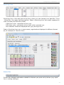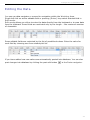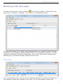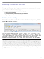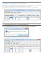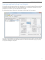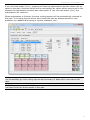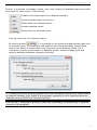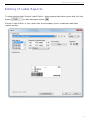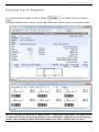
1
CutLogic 2D User’s Manual Top class optimization software Product of www.tmachines.com C utLogic 2D, © TMachines, s.r.o. Table of Contents Welcome Contact and Support Introduction What is CutLogic 2D? What's New in Current Version? Technical Specifications Before You Try System Requirements Download and Installation Trial Version Before You Buy Editions Comparison Ordering and Purchasing Registration Program Overview General The Main Window The Menus Sorting the Data Editing the Data Filtering the Data Keyboard Shortcuts Setting the Options Working with Inventory General Working with Materials Working with Assemblies Working with Storages Working with Plans General Adding a New Empty Plan Duplication of Existing Cutting Plan Entering Sources for the Plan Entering Parts for the Plan Entering Settings for the Plan Entering Multiple Plans from an Assembly Running Optimization Opening and Closing the Plan Reports General The Reports Window Editing of Standard Reports Editing of Label Reports Previewing of Reports Import General How to Import Data Examples of Imports Export General How to Export Data 4 5 6 6 7 11 12 12 13 14 15 15 17 18 20 20 22 26 28 29 30 33 35 44 44 45 48 50 51 51 52 53 54 57 61 67 70 75 76 76 78 83 84 88 89 89 90 93 98 98 99 2 C utLogic 2D, © TMachines, s.r.o. Database Administration Network Installation 103 110 3 C utLogic 2D, © TMachines, s.r.o. Welcome to CutLogic 2D! Thank you for your interest in CutLogic 2D - panel cutting optimization software. CutLogic 2D is a solution for finding optimal cutting layouts with minimal waste, saving your material, time and money. Since 2002 TMachines has provided top class software solutions in the area of cutting optimization for their customers. CutLogic 2D brings you the best of our know-how as well as many improvements inspired by our customers. We know every customer has specific needs, therefore we have prepared well tuned editions of CutLogic 2D: • Standard Edition (SE) Ideal solution designed for individuals or as a starter package for small and medium business (SMB) segments. This edition provides full Inventory Management and state-of-the-art optimization engine based on AI programming technique, the same one for all editions. No customization and no editable reports are available for this edition. • Professional Edition (PE) Right solution designed for needs of SMB. It provides full Inventory Management and state-of-the-art optimization engine based on AI programming technique, the same one for all editions. This edition supports more import/export formats and contains embedded report designer for customization of reports. On demand customization of software is possible only for reports and import/export functionality. • Enterprise edition (EE) Solution designed for enterprise customers. It provides full Inventory Management and state-of-the-art optimization engine based on AI programming technique, the same one for all editions. All input/output formats are supported in this edition. Also full on demand customizations and extra Enterprise+ add-ons are available for this edition. See chapter Edition comparison for details. Today, our solutions help companies in more than 65 countries worldwide on daily basis to maximize their cost savings. We believe you will be satisfied with our program and we wish you a lot of savings with CutLogic 2D . Authors 4 C utLogic 2D, © TMachines, s.r.o. Contact and Support Feel free to contact us via e-mail in any matter related to our products and services. We will make sure your inquiries will be processed and answered as soon as possible. Non technical questions If you have any general questions or any non technical questions regarding pricing, ordering and licensing of CutLogic 2D , please contact us at: E-mail: Technical questions If you have any technical questions regarding CutLogic 2D 's functionality, features, working with program or modifications, please contact us at: E-mail: See also our regularly updated web for news and updates at: www.tmachines.com Street and mailing address: 5 C utLogic 2D, © TMachines, s.r.o. Introduction What is CutLogic 2D? CutLogic 2D is a top class panel cutting optimization software for cutting rectangular material like panels, sheets or rolls in industries such as woodworking, furniture, sheet metal, glass cutting, etc. CutLogic 2D automatically finds optimal cutting layouts, using the most advanced optimization techniques. Its optimization engine takes advantage of Genetic Algorithms and Fuzzy Logic which represent fundamental techniques of modern Artificial Intelligence and bring better results than any other software. CutLogic 2D is a complete solution for both guillotine and non-guillotine cutting, based on IT standards with friendly user interface. It provides extensive features such as full material and remnant management, enhanced reporting functionality or multi format import and export of data for seamless integration with your existing working system and much more. Genetic Algorithms and Fuzzy Logic Genetic Algorithms Genetic algorithm is an algorithm that mimics evolution and competition between individuals in natural selection. Tasks are encoded to genes of individuals and evolution produces better individuals with better solving. Neither programmer nor genetic algorithm has to know how to solve a given problem; solution is just bred. Genetic algorithms and genetic programming belong to evolutionary computation and artificial intelligence. Fuzzy Logic Fuzzy Logic is a truth-functional system that mimics natural thinking in a sense of dealing with the degree of truth rather than just with True and False. In Boolean logic an event can be only False (0) or True (1); in fuzzy logic an event can be sort of true - a number between 0 and 1. 6 C utLogic 2D, © TMachines, s.r.o. What's New in CutLogic 2D Version 3.8? What's New in Version 3.8? Optimization & cut options Added full support for cutting from rolls and slitting & shearing Adjustable maximum number of knives / cuts (both vertical and horizontal) Reports Capability to create charts General Configurable sorting of layouts and layout parts Several smaller improvements and fixes Version 3.7 Optimization & cut options Added cutting option Minimum repeat of layouts General Several smaller improvements and fixes Version 3.6 Optimization & cut options Added cut table length – maximum length of horizontal cuts Added cut table width – maximum length of vertical cuts Improved constraint Grip size – now allow also parts smaller than grip General Closed plans can be deleted now Material lookup table sorted by description Several smaller improvements and fixes Version 3.5 Import/Export Added import and export of whole plan from/to single file 7 C utLogic 2D, © TMachines, s.r.o. General Several smaller improvements and fixes Version 3.4 Import Added support of feet & inches in imports General Several smaller improvements and fixes Version 3.3 Export Export to dxf files General Several smaller improvements and fixes Version 3.2 Optimization & cut options New cutting setting Grip allowing definition of minimum grip on both sides of each cut General Several smaller improvements and fixes Version 3.1 Optimization & cut options Improved optimization engine - higher overall yield and lower overall cost and waste Added several new 2-stage and 3-stage cutting types See more in chapter Entering Settings for the Plan (Type of cutting). General Creating multi-material plans from Assemblies Several smaller improvements and fixes 8 C utLogic 2D, © TMachines, s.r.o. Version 3.0 The following describes changes against version 1.5 Technology MS Vista OS supported Firebird RDBMS used - more secure and reliable solution based on true SQL database for data protection like security, backup, crash recovery, etc. GUI Graphical redesign and optimization of program for more user friendly look and feel Enhanced data grids for better navigation and data manipulation – new sorting and multi sorting features Enhanced filtering capabilities – possibility to define new improved filters for Plans, Materials, Assemblies, Storages, Sources, Parts, etc. New features New Inventory management of sources, parts and remnants integrated with plans Assemblies Enhanced Group Optimization Duplicate plan Reports New - filtering by date Export embedded into Reports New embedded report generator and editor for customization of reports Improved and extended labeling systems and report sets Possibility to define custom defined data views and statistics Batch reports Imports Import of multi-material data with automated creation of plans Added import from MS Excel files, MS Access files, CSV format Added import from data sources (Oracle, MS SQL Server, MySQL, Firebird, etc.) via connection string Added "default" values and "multiply by" values when defining import Added filter allowing to filter imported data Improved import, sorting capabilities for imported data Exports Export to CSV, MS Excel files, PDF, XML, Open Document Text, Open Document Spreadsheet Send by email feature Improved export to TXT, RTF, and HTML 9 C utLogic 2D, © TMachines, s.r.o. Connectivity Distributed connectivity allowing various scenarios in different environments (local, LAN, WAN) Improved support for LAN – user management, logon security, etc. WAN optimization - application optimized for running in WAN environment 10 C utLogic 2D, © TMachines, s.r.o. Technical Specifications Sources (stock material): Max length and width of source: 100,000,000 (100 million) Max number of sources per plan: 1,000,000 (1 million) Max sum area of sources per plan: 100,000,000,000,000 (100 million million) Max number of source sizes per plan: 10,000 (10 thousand) Parts (pieces to cut): Max length and width of part: 100,000,000 (100 million) Max number of parts per plan: 1,000,000 (1 million) Max sum area of parts per plan: 100,000,000,000,000 (100 million million) Max number of part sizes per plan: 10,000 (10 thousand) 11 C utLogic 2D, © TMachines, s.r.o. Before You Try System Requirements CutLogic 2D has been designed to work with Microsoft Windows 2000, XP, Vista, Windows 7. Minimum Intel Pentium® III 800 MHz or AMD Athlon 800 MHz 512 MB RAM (1024 MB RAM for Windows 7) Display 800x600; 65,536 colors 30 MB of free Hard Disk space Microsoft Windows 2000/XP/Vista/Windows 7 Mouse Recommended Pentium® 4 or AMD Athlon – 1400 Mhz or more 1054 MB RAM (2048 MB RAM for Windows 7) True Color Video Card (16,8 M colors) - 1024x768 50 MB of free Hard Disk space Microsoft Windows 2000/XP/Vista/Windows 7 Mouse 12 C utLogic 2D, © TMachines, s.r.o. Download and Installation Download You are welcome to download the trial version of our software at www.tmachines.com . You can freely download CutLogic 2D and run it on your computer for a trial period of 30 days. Click the download link in Download section. Downloading should start automatically. Installation After the download is finished, go to the download folder and locate the file (i.e. setupcl2d.exe). Double-click the file to start the installation. 13 C utLogic 2D, © TMachines, s.r.o. Trial Version The CutLogic 2D is available in three editions: Standard, Professional and Enterprise. The most of features and functions in trial edition is unlocked on Enterprise level in order to demonstrate its capabilities; however some features are not available in trial edition. See chapter Editions comparison for details. When launching CutLogic 2D in trial mode following dialog appears at start: You can see how many days remain till the end of trial period and you can also order and register full version of the program. Click the button [Continue] to start program. 14 C utLogic 2D, © TMachines, s.r.o. Before You Buy Editions Comparison Trial Edition Standard Professional Enterprise Edition Edition Edition Program limitations Time limitation 30 days Unlimited Unlimited Unlimited Plan limitations [per one cutting plan] Max total number of all parts Unlimited 1,000 10,000 Unlimited Max number of unique parts (part sizes) Unlimited 20 100 Unlimited • • • • • • • • • • • • Network features LAN support WAN support Product features 20 predefined reports • • • • • • • • • • • • • • • • • • • • • • • • • • • • • • • • • • • • • • • • • • • • • • • • • • • • • • • Fully customizable reports Inventory Materials and Storages Inventory Assemblies - copy to plan Inventory Assemblies - copy to multiple plans Types of cutting Unrestricted (non-guillotine) Guillotine 3-stage relaxed 3-stage exact 2-stage relaxed 2-stage exact 2-stage simple (slitting & shearing) Cutting settings and parameters Horizontal / vertical saw kerf (cut width) Left / right / top / bottom trim cut Minimum size of remnant (reusable rest) Storage for new remnants Remnants production control Grip size C ut table length - max length of hor. cuts C ut table width - max length of ver. cuts Group/order optimization Minimum length of roll - cutting from rolls Limit for number of partially used rolls Limit for slitting knives settings per roll • • • • • • • • • 15 C utLogic 2D, © TMachines, s.r.o. Minimum layout repeat Limit for number of horizontal knives / cuts Limit for number of vertical knives / cuts • • • • Small sources usage control • • • • Import from C lipboard TXT format C SV format MS Excel format • • • • • • • • • • • • • • • • • • • • • • • • • • • • • • • MS Access format C onnection string file Export to DXF (AutoCAD) format TXT format C SV format MS Excel format PDF format HTML format XML format RTF format ODT format ODS format • • 16 C utLogic 2D, © TMachines, s.r.o. Ordering and Purchasing Order the registered version of CutLogic 2D on-line through the World Wide Web at our site www.tmachines.com . Here you find our latest pricing information, instructions on how to order, and link for ordering online using a secure server, or by phone or fax. Our registrations are handled by a professional software registration company. You can order CutLogic 2D securely online, or by fax, through share-it!, global e-commerce provider for software sales via Internet. You can use a credit card, debit card, bank transfer, check, cash, or purchase order / order on account, including billing in various currencies. You can also order CutLogic 2D directly at and pay via wire transfer to our bank account after getting an electronic invoice from us. When purchasing CutLogic 2D, technical support by email and upgrades for the first year are included. 17 C utLogic 2D, © TMachines, s.r.o. Registration When you start CutLogic 2D , "CutLogic 2D Trial" dialog window displays your remaining trial period. Click the [Order and registration] button and follow the instructions. 18 C utLogic 2D, © TMachines, s.r.o. NOTE! After we receive the license fee and Machine ID, we send you (usually in several hours) a registration key by e-mail with detailed instructions on how to use it. Email will be sent to the e-mail address that you stated in the order. 19 C utLogic 2D, © TMachines, s.r.o. Program Overview General This chapter describes basic information about CutLogic 2D program good to know before you start to use the program. The Basic Concepts and Terms This chapter explains basic concepts and commonly used terms used in the program. Commonly used terms Program or CutLogic 2D means CutLogic 2D software application. Optimization is process of finding the cutting plan with the optimized cutting layouts. Plan represents definition of cutting plan. Source represents material available for cutting; it is input into cutting plan. Part represents piece of material required to be cut; it is input into cutting plan. Remnant represents reusable rest of Source (also called reusable off-cut). Scrap represents useless rest of Source. View represents unique point of view or perspective on data. Master View represents master part of View. Detail View represents detailed part of View. Master Tab is graphical control element (button) in the Program displaying given Master View. Detail Tab is graphical control element (button) in the Program displaying given Detail View. Report represents special layout displaying the data in printable format. Filter represents set of conditions filtering data in given View or in given Report. Material represents definition of unique material. One plan may contain only one Material. Assembly represents unique definition of logically grouped Parts. Storage represents definition of unique logical or physical storage or warehouse for Materials. 20 C utLogic 2D, © TMachines, s.r.o. Basic concepts All data in CutLogic 2D are stored in database in form of the database tables. Data from the database are displayed via Views. Views represent unique point of view on the data. CutLogic 2D contains following Views: Plans Materials Assemblies Storages You can switch among these Views by clicking one of the Icons representing given view in the Tool Panel. Every View consists of one Master View and one or more Detail Views. Master View is represented by Master Tab in the program, Detail View is represented by Detail Tab . Master Tab is first tab displayed in Tab Area from the left and contains small icon. Active Views are displayed at Tab Area in following way: CutLogic 2D is unique in term of handling and displaying master–detail relations of data. If Detail View is active, following navigator is displayed in Tool Panel: This navigator allows you to browse the records in related Master View while detailed information for active Detail View is displayed on the screen. This is very helpful feature allowing you better orientation among your data. 21 C utLogic 2D, © TMachines, s.r.o. The Main Window This chapter describes basic information about Graphical User Interface of CutLogic 2D . The Main Window contains following areas: Main Menu This drop-down menu is basic control element for navigation and executions of logically grouped commands. Main Toolbar The Toolbar is a collection of buttons and other control elements providing quick access to commonly used commands. Plans [Ctrl+1] Activates the Plans view allowing you to manage your plans, their sources, parts, settings and results Materials [Ctrl+2] Activates the Materials view allowing you to manage your materials, their sources and parts 22 C utLogic 2D, © TMachines, s.r.o. Assemblies [Ctrl+3] Activates the Assemblies view allowing you to manage your assemblies and their parts Storages [Ctrl+4] Activates the Storages view allowing you to manage your storages and their sources Reports [Ctrl+P] Displays the Reports form with list of available reports in new window Filter [Ctrl+F] Displays the Filter definition form in new window Import [Ctrl+I] Displays the Import form in new window Start Optimization [F3] Starts calculation of optimal cutting plan for given actual plan Stop Optimization [ESC] Stops calculation Following data navigator serves for navigation in given Master View . This navigator is displayed only if other than Master Tab is chosen (active). This navigator allows you to browse the records in given Master View while detailed information from active Detail View is displayed in Working Area . Function of the buttons of navigator is following: First record of given Master View Prior record of given Master View Next record of given Master View Last record of given Master View Tabs Area Tabs are graphical control elements representing Master and/or Detail Views. Tabs Area shows one Master and one or more Detail Tabs. Master Tab is the first tab from the left in Tabs Area and contains small graphical icon. 23 C utLogic 2D, © TMachines, s.r.o. Control Panel Control Panel displays basic information about active Master View and contains data navigator used for navigation in Working Area and optionally displays other control elements (buttons). Data navigator Data navigator serves for navigation and editing of data displayed in Working Area . Function of the buttons of navigator is following: Sets the current record as the first record Sets the current record as the previous record Sets the current record as the next record Sets the current record as the last record Inserts a new record Deletes the current record Posts changes from the current record to the database Cancels changes made in the current record 24 C utLogic 2D, © TMachines, s.r.o. Working Area Working Area is the main part of the form, where you can manage your data like Plans , Materials, Storages and Assemblies. Data in Working Area are usually organized in rows (records) and columns (fields). Light blue color represents active row . Dark blue color represents active field within selected row. Non editable fields are displayed with grey background. Data in Working Area are, in some cases, organized and displayed in different format as, for example, in Results form: Status Bar Status Bar displays information related to element you point on by mouse (e.g. input line in cutting settings). 25 C utLogic 2D, © TMachines, s.r.o. The Menus File Plans [Ctrl+1] Inventory Activates the Plans view allowing you to manage your plans, their sources, parts, settings and results. This contains following three sub-menu options... Materials [Ctrl+2] Activates the Materials view allowing you to manage your materials, their sources and parts. Assemblies [Ctrl+3] Activates the Assemblies view allowing you to manage your assemblies and their parts. Storages [Ctrl+4] Activates the Storages view allowing you to manage your storages and their sources. Start Optimization [F3] Starts calculation of optimal cutting plan for given actual plan. Stop Optimization [Esc] Stops calculation. Reports [Ctrl+P] Displays the Reports form in new window. Allows working with available reports like printing, previewing, editing and others. Filter [Ctrl+F] Displays the Filter definition form in new window. Allows defining filter conditions and others. Import... This contains following four sub-menu options... Import data from Excel, Access, csv, txt or connection file... [Ctrl+I] Displays the Import form in new window. Allows importing data. Import data from clipboard [Ctrl+J] Allows importing data from clipboard. Import plan from single file (to new plan) [Ctrl+K] Allows importing whole cutting plan from single data file. The data are imported to new created plan. Import plan from single file (to current plan) [Ctrl+L] Export... Export data to csv, Allows importing whole cutting plan from single data file. The data are imported to currently selected plan. This contains following three sub-menu options... [Ctrl+P] Displays the Reports form in new window. 26 C utLogic 2D, © TMachines, s.r.o. txt, Excel, pdf, rtf, html, etc... Export plan to single file... Allows exporting data to csv, txt, xls, pdf, html, xml, rtf, odt or ods file. [Ctrl+E] Export cutting layouts to dxf files... Allows exporting current plan to single data file. Opens file save dialog. Allows exporting cutting layouts to dxf file. Exit Quits the application. Tools Calculator [F8] Database Displays the windows calculator. This contains following four sub-menu options... Data Opens the Data Administration on Data Tab in new window. Allows setup of backup and restore procedures. Server Opens the Data Administration on Server Tab in new window. Allows setup of server connection. Users Opens the Data Administration on Users Tab in new window. Allows managing the users. Stats Opens the Data Administration on Stats Tab in new window. Shows database statistics. Order and Registration Options... Displays the information how to order and register the full version. [Ctrl+O] Displays the Options form with program options in new window. Help CutLogic 2D Help [F1] Displays the Contents of this help file. CutLogic 2D Online Help Opens CutLogic 2D online help in your web browser. Visit CutLogic 2D Web Site Opens homepage of CutLogic 2D in your web browser. About Displays the information about the Product name and current version. It also contains the support link and our website address. 27 C utLogic 2D, © TMachines, s.r.o. Sorting the Data This feature helps you to manage your data displayed in Working Area. Click the label of given column by left mouse button to sort displayed records. Records will be sorted according to data values in selected Column. First click sorts data in ascending order. Second click sorts data in descending order. Third click cancels sorting in selected column. Program also allows defining of sorting over multiple columns. Hold [Ctrl] button and click by left mouse button on the labels of given columns to activate sorting in more columns. Following example shows sorting applied in "Length" and "Width" columns: 28 C utLogic 2D, © TMachines, s.r.o. Editing the Data You can use data navigator or mouse for navigation within the Working Area. Single left click on active editable field or pressing [Enter] key switch selected field in Edit mode. Edit mode allows you either to enter the data directly from the keyboard or to pass data from the clipboard. Some fields are restricted only by the length – the maximum number of characters. Some editable fields are restricted by the list of predefined values. Enter the value for such field by choosing one from related pick list. If you leave edited row new values are automatically posted into database. You can also post changes into database by clicking the post edit button in the Data navigator. 29 C utLogic 2D, © TMachines, s.r.o. Filtering the Data Filters represent powerful tool for data presentation. You can restrict displayed data by defining filtering conditions in Filter definition form. You can define one unique filter for each of following Views: Plans Plan Sources Plan Parts Materials Material Sources Material Parts Assemblies Assembly Parts Storages Storage Sources Definition of Filter By clicking the button in the Main Toolbar or by pressing keyboard shortcut [Ctrl+F] the Filter definition form opens in new window. 30 C utLogic 2D, © TMachines, s.r.o. Filter definition form may contain more filtering conditions. Define logical relation among these conditions by clicking one of following radio buttons: Match all of the following Only data which fulfill all of the defined conditions will be displayed. Match any of the Only data which fulfill at least one of the defined conditions following will be displayed. Adding and Deleting the Conditions You can add and delete conditions of filter by clicking the chosen button . Functions of the buttons for manipulation with the filter are described as follows: New condition will be added at the end of already defined conditions. It is possible to define 9 conditions at most. The last condition in the filter will be deleted. All defined conditions will be deleted. Defining and Editing the Conditions You need to choose a column, operation and define the value for each of conditions. Select column from pre-defined list of available columns. You can define conditions even for columns not displayed in given View. 31 C utLogic 2D, © TMachines, s.r.o. TIP! Select "Any Field" value from the list if you need to define condition for all available columns! Select operation from pre-defined list of operations and enter the value for setting the filter. NOTE! Use numeric value for numeric columns like "Plan ID" or "Qty". For other columns any string can be used. Activation and Deactivation of Filter When all conditions of the filter are set, you can activate it. For activation click the check box "Active" in the Filter definition form. The filter will display only the records which fulfill defined conditions. Activation of filter is signalized by the red labeled information in Control panel. 32 C utLogic 2D, © TMachines, s.r.o. Keyboard Shortcuts Shortcuts for quick access to the program features: [Tab] Moves to the next field (cell) [Shift+Tab] Moves to the previous field (cell) [Alt+Arrow Down] Drops down list [Ctrl+1] Opens Plans [Ctrl+2] Opens Materials [Ctrl+3] Opens Assemblies [Ctrl+4] Opens Storages [F3] Starts calculation of optimal cutting plan [Esc] Stops calculation [Ctrl+F] Opens Filter definition form [Ctrl+P] Opens Reports form [Ctrl+O] Opens Options form [Ctrl+I] Opens Import form [Ctrl+J] Imports data from clipboard [Ctrl+K] Imports cutting plan from single data file (to new plan) [Ctrl+L] Imports cutting plan from single data file (to current plan) [Ctrl+E] Exports current plan to single data file [F8] Opens Windows calculator [F1] Opens Help In database grids only: [F2] Edits current field / Opens pick list for current field / Switches source qty 0 <-> unlimited [Esc] Cancels edit mode [Ctrl+Del] Deletes current record [Ins] Inserts new record [Arrow Up] Moves to the previous record [Arrow Down] Moves to the next record [Page Up] Moves to the previous page of records [Page Down] Moves to the next page of records [Ctrl+Home] Moves to the first record [Ctrl+End] Moves to the last record [Enter/Return] Switches between field's edit and view modes [Arrow Left] Moves to previous field (only if current field is in view mode) 33 C utLogic 2D, © TMachines, s.r.o. (same as [Shift+Tab]) [Arrow Right] Moves to next field (only if current field is in view mode) (same as [Tab]) [Home] Jumps to first (most left) field (only if current field is in view mode) [End] Jumps to last (most right) field (only if current field is in view mode) 34 C utLogic 2D, © TMachines, s.r.o. Setting the Options To work with Options, select the menu item "Tools > Options..." or use [Ctrl+O] keyboard shortcut. In Options you can set the main parameters of the program. Correct representation and displaying of the data in the project depends on setting of some parameters like Type, Precision and Unit. That is the reason why we recommend to set these options immediately after the first start of the program or before entering of new cutting project. Formats In this option you can set Type, Precision and Unit for Length and Area formats of materials. Setting options for "Type" are given in following table: Type Decimal e.g. 123,324 mm; 234,34 m; 142,2" Feet and decimal inches e.g. 833' 3,99" Fractional e.g. 324 31/32" Feet and fractional inches e.g. 1302' 63/64" In option "Precision", you can set the precision of entering the length format (decimal places, fractions) according to setting of the type. In option "Unit", you can set the length unit of material (mm, cm, dm, m, '', ', in, ft). 35 C utLogic 2D, © TMachines, s.r.o. This option is accessible only when the decimal or fractional type is set. When other types are set, this option is disabled. Defined Unit is shown in the length and width of material in the program and also in printing reports. TIP! You can also set your own length unit by writing it to combo box or you don't need to fill it in at all. In this case the length unit won't be shown. NOTE! Because for each length format internal storage of data is different, change of length type and precision doesn't convert already entered data. Therefore, it is necessary to consider this option carefully at the beginning of working with this program. Zero suppression In this option you can set suppression of displaying zero values. Leading Suppresses displaying of leading zeros in decimal numbers. Trailing Suppresses displaying of trailing zeros in decimal numbers. 0 Feet Suppresses displaying of 0 feet. 0 Inches Suppresses displaying of 0 inches. 36 C utLogic 2D, © TMachines, s.r.o. Costs Cost of sources Costs of sources allows you to choose the most suitable costs metric for your sources. Cost metric Description 1 square unit Value in the field Cost represents cost of 1 square unit of source; square unit is defined by "Area display format" and "Divider" value Whole source Value in the field Cost represents cost of the whole source 1000 length units Value in the field Cost represents cost of 1000 length units of source 100 length units Value in the field Cost represents cost of 100 length units of source 10 length units Value in the field Cost represents cost of 10 length units of source 12 length units Value in the field Cost represents cost of 12 length units of source 1 length unit Value in the field Cost represents cost of 1 length unit of source 37 C utLogic 2D, © TMachines, s.r.o. Plan sources costs check You can also define maximal ratio between the highest and the lowest cost of source within the plan. If this ratio is exceeded following warning message appears. 38 C utLogic 2D, © TMachines, s.r.o. Optimization Group optimization Here you can set the columns used for automatic writing of its values into the S-Group field in the Plans Sources form. When Group optimization is turned on an identifier is used for grouping the sources by value written in the S-Group field. Default value Description Nothing S-Group won't be automatically populated Manufacture date S-Group will be automatically populated by Manufacture date Origin ID S-Group will be automatically populated by Origin ID Storage S-Group will be automatically populated by Storage Description S-Group will be automatically populated by Description Note 1 S-Group will be automatically populated by Note 1 Note 2 S-Group will be automatically populated by Note 2 NOTE! Material's Origin ID is a value, which represents the original material it was cut from. E.g. remnant 340 cut from remnant 233 which is cut from original material 123 will have Origin ID 123, this way each remnant can be traced to its original material. See more in chapter Entering Setting for the Plan (What is Group optimization?). 39 C utLogic 2D, © TMachines, s.r.o. Layouts In this option you can set sorting of cutting layouts and cutting layout parts. Each of this data can be sorted by three different fields in individual ascending or descending order. Layout Pictures In this option you can set some properties for the displaying of layout pictures in program and reports. 40 C utLogic 2D, © TMachines, s.r.o. Origin of layout Here you can set origin of the layout. LeftTop Layout starts from the left and top side. LeftBottom Layout starts from the left and bottom side. Layout Pictures in Program (Reports) Here you can set expression for description of parts in pictures and background colors in results form or printing reports. Part description It is possible to enter any text, variables and tags which define font styles in script. Following text describes how to enter expression for description of parts in layout pictures. It is possible to enter any text, variables and tags which define font styles in script. Variables Every variable starts with @ and it is possible to enter following variables: @PartID Part ID @X1-coord X1 Coordinate (Left) @Y1-coord Y1 Coordinate (Bottom / Top)* @Length Part Length @Width Part Width @Turned Indicates Rotation of Part @OrderNumber Order Number @PartGroup Part Group @Description Description @Note-1 Note 1 @Note-2 Note 2 *According to setting of Origin of the layout in Options Tags <B> ... </B> Bold <I> ... </I> Italic <U> ... </U> Underline 41 C utLogic 2D, © TMachines, s.r.o. In the following table is an example of usage: Input (Script you enter) Output (Text you see in part) <B>#@PartID</B> @Length x @Width <U>@OrderNumber</U> @Description #22 726 x 400 16686394 Flat shelf Background colors Here you can set individual background color for Layouts, Parts, Remnants and Scraps in program and reports. Part colors User defined Color for parts will be defined by user in Background colors - Parts. Random Random colors for parts will be generated by the program. Shades of gray Shades of grey for parts will be generated by the program. Click button [Load default] if you want to load default settings. 42 C utLogic 2D, © TMachines, s.r.o. DXF Export In this option you can set properties of dxf file which can be used to export cutting layouts in CAD exchange format (AutoCAD Drawing Exchange Format). System is designed to create one file for each layout. Visible objects in matching layers Here you can set which objects (Source, Parts, Part description, Header & Table) will be exported to dxf file. It is also possible to assign layer name to each object separately. It means, that object will be visible only in layer with appropriate layer name. Layer names and colors In this option you can define layer names and suitable colors. Part description If you want parts to include part description it is possible to define it here. Definition of part description for dxf file is the same as definition of part description for layout pictures in program (reports). The only difference is that you can't define tags here. Auto export path Program enables you to automatically save dxf files after optimization. If you want automatically save these files, you can set correct path here and after each optimization new dxf files will be created in this folder. 43 C utLogic 2D, © TMachines, s.r.o. Working with Inventory General Inventory is a complement part of the program. It is used for inventorying and overall easy work with the program. You can keep here types of materials and their sources and you can also define the storages where the sources are actually placed. You can define Assemblies in order to save time and simplify working with plans. There are two different ways how to utilize the Inventory . Using Inventory only for pre-defined or virtual materials and their sources and/or parts. If you want to use CutLogic 2D only for optimization purposes and if you keep real materials in different Inventory systems you can use CutLogic 2D Inventory only for pre-defined or virtual materials and/or for pre-defined or virtual sources and parts. When defining plan, you can copy pre-defined sources and/or pre-defined parts from Materials and save time needed for manual entry. Using Inventory in standard way. In such case all standard Inventory functions are utilized. All movements of physical material are tracked, you can run physical inventory, etc. See chapter Opening and Closing the Plan for related consequences. Inventory consists of these three parts: Materials Assemblies Storages 44 C utLogic 2D, © TMachines, s.r.o. Working with Materials To work with Materials, click the button in the Main Toolbar or select the menu item "File > Inventory > Materials" or use [Ctrl+2] keyboard shortcut. Click the Materials master tab to add new material and/or change descriptive information about existing materials. When new material is added you can continue in defining of sources, parts and cut settings. Sources tab Click the Sources tab to define sources of actually set material. These sources are your real inventory and you can associate them to the concrete Storage through the field "Storage". If no Storage is defined, default storage will be used implicitly. You can enter 45 C utLogic 2D, © TMachines, s.r.o. a short description of source to the field "Description". The field "Cost/unit" represents the cost of material. The fields "Length" and "Width" represents the length and width of the source and the field "Qty" represents total number of available sources. NOTE! Every line (record) in Sources represents unique micro batch with unique ID called "Origin ID". When defining a new source "Origin ID" is automatically set by program and is equal to "Source ID" displayed in Working area. All parts and remnants being cut from this micro batch share the same "Origin ID". It is extremely useful for tracking purposes of given material from original source through sub-sources or remnants to final parts. "Origin ID" is not displayed in the program, however it can be utilized in filters and reports. It is possible to import sources of materials from any file with any structure or from clipboard. NOTE! Sources which are defined in Materials are your real inventory. When you define and use them, you get a transparent overview of movement of materials and overall inventory in storages. IMPORTANT! Sources with unlimited "Qty" represent pre-defined or virtual ones! Such sources are not part of your real inventory! Parts tab Click the Parts tab to define parts for given material. Defining of parts in Materials can be useful in cases when these predefined parts are frequently used in plans, so that copying these parts from Materials may save time and simplify preparation of new cutting plan. 46 C utLogic 2D, © TMachines, s.r.o. Settings List tab Settings list tab allows you to define list of pre-defined plan settings for given material. See more in chapter Entering Setting for the Plan. 47 C utLogic 2D, © TMachines, s.r.o. Working with Assemblies Working with Assemblies allows you to define assemblies (products) and their parts. When defining plan, this functionality allows you to copy entire assemblies instead of their parts into given plan. It brings simplification and streamlining to your work. See chapter Entering Multiple Plans from an Assembly for more information. To work with Assemblies, click the button on the Main Toolbar or select the menu item "File > Inventory > Assemblies", or use [Ctrl+3] keyboard shortcut. Assemblies tab allows you either to define new assembly and related descriptive information or to edit existing ones. 48 C utLogic 2D, © TMachines, s.r.o. Parts tab Parts tab allows you to define parts for given assembly. Parts in assemblies represent bill of materials. This is new point of view on how to work with parts. It can be very useful in cases when you prepare cutting plan with many assemblies. This feature brings time saving and simplifies preparation of the new cutting plan. 49 C utLogic 2D, © TMachines, s.r.o. Working with Storages To work with Storages, click the button in the Main Toolbar or select the menu item "File > Inventory > Storages" , or use [Ctrl+4] keyboard shortcut. Storages tab allows you to define your storages where your material is kept. Storage numbered 1 is pre-defined storage (Default) and it is not possible to delete it. You can change its Description for better customizing. If you don't define other storage when defining plan, pre-defined storage (Default) will be used. Sources tab Sources tab allows you to see the list of materials stored at currently set storage. It is not possible to make any changes in this view; it is for information purpose only. 50 C utLogic 2D, © TMachines, s.r.o. Working with Plans General To work with Plans, click the button in the Main Toolbar or select the menu item "File > Plans" or use [Ctrl+1] keyboard shortcut. Plans are the main part of the program where you can set and manage cutting plans, sources of material, desired parts to cut and also perform the optimization of cutting layouts. You can create new cutting plan in one of the following ways: Entering plan manually Entering plan (multiple plans) from Duplication of existing plan Import of multi material parts Assemblies 51 C utLogic 2D, © TMachines, s.r.o. Adding a New Empty Plan To add a new empty cutting plan, first click the Plans tab to open Plans form. Next, click the button in the Data navigator to add a new plan. Next, enter "Description" of the plan. Move to the field "Material" and click left mouse button or press [F2] key to open drop-down list showing your Materials in the Inventory. Choose one of them and insert it to the plan. Field "Material" is mandatory. If you do not use Inventory features you can leave this field without editing and "Default" material is set automatically. "Default" material is predefined in the program and can not be deleted from Materials. NOTE! You can define as many plans as you need for one material. However, one plan may contain only one material! 52 C utLogic 2D, © TMachines, s.r.o. Duplication of Existing Cutting Plan You can add new plan by duplicating the existing one. First, activate the plan you want to duplicate by clicking on it. Then click the button [Duplicate] in Control Panel and choose an option from the pick list as is shown in the following picture: • Choice Plan will copy only related data from Plans tab and also defined parameters from Settings tab of selected plan into a new plan. • Choice Plan & Sources will copy related data from Plans tab and defined parameters from Settings tab and all sources defined in Sources tab of selected plan into a new plan. • Choice Plan & Parts will copy related data from Plans tab and defined parameters from Settings tab and all parts defined in Parts tab of selected plan into a new plan. • Choice Plan & Sources & Parts will copy all related data from selected plan into a new plan. This feature allows you to copy all section or only selected sections of given plan into new one. It is useful in "Multi plans", where an order consists of more plans with different materials. 53 C utLogic 2D, © TMachines, s.r.o. Entering Sources for the Plan When general information about the plan is entered, you can start to enter the sources, one of mandatory input for the optimization. You can enter sources in one of the following ways: Entering sources directly Copying stored or predefined sources from Materials Importing sources from external data files Entering sources directly Click the Sources tab to open Plan Sources form. To add new cutting source, click the button in the Data navigator. Now you can enter data in the fields "Length", "Width", "Qty", "Cost/unit", "Mnf. Date", "S-Group", "Description", "Note 1" and "Note 2". "Length", "Width" and "Qty" are mandatory fields. First, enter length of the source to the field "Length". Next, enter width of the source to the field "Width". Next, enter the number of pieces available for cutting to the field "Qty". Fields "Used" and "Storage" are not editable. TIP! How to use CutLogic 2D for estimation of optimal quantity of sources in the plan? If you know what parts you want to cut, what dimensions of sources are going to be used, but you do not know how many sources of given length and width you should order, just select "unlimited" value in the field "Qty". Program will automatically find optimal usage of that source during optimization. Consequently, you can order only the material you need for the plan and you don't need to keep material in storage. Next, you can enter the unit cost of the source to the field "Cost/unit" according to pre-defined Costs format in Program options. 54 C utLogic 2D, © TMachines, s.r.o. IMPORTANT! You can leave field "Cost/unit" blank – this is not mandatory field for optimization. CutLogic 2Doptimizer is based on cost optimization – it means the optimizer is trying to find "the cheapest" cutting plan (layouts). In the case when "Cost/unit" fields are blank or contain the same value for all sources within given plan – in other words if cost priority is not used – we talk about yield optimization which is a special case of cost optimization. In such case optimizer finds optimal cutting plan with the maximal yield and minimal physical waste. Because of the sam e cost of all sources it is also the cheapest cutting plan. In case when you set different costs for different sources the optimizer finds the cheapest cutting plan, which isn't necessarily the plan with maximal yield/minimal waste. TIP! You don't need to assign the real cost to the "Cost/unit" field. "Cost/unit" field can be also understood and used as a priority – sources with lower cost are used in optimization process with greater priority. Copying stored or predefined sources from Materials The second way how to enter the sources to the plan is to load them from Materials. By clicking the button [Material], the Material Sources form with predefined sources opens. You can mark one or more sources and copy them to the plan by clicking the button [Copy to plan]. TIP! Click the button [Mark all] to mark all available sources. 55 C utLogic 2D, © TMachines, s.r.o. After clicking the button [Copy to plan] following confirmation form appears: After clicking the button [Yes] the sources are copied to the plan. IMPORTANT! Keep in mind that sources with defined quantity represent real sources of real Inventory and you can not edit them in this form, while sources with "unlimited" quantity represent predefined sources – templates. Such kind of source is virtual one and it can not be stored in Storages so that Storage field is blank. You can edit and change the same fields as in manual mode of entering the sources. Importing sources from external data files The third way how to enter the sources to the plan is to import them from the external data files. It is possible to import sources from any of following structured files: TXT, CSV, MS Excel file, MS Access file, from clipboard or from an external database via connection string definition. You can import sources from external source by clicking the menu "File > Import" or by pressing [Ctrl+I] keyboard shortcut. Read more about import in chapter Import. TIP! It is possible to combine all above mentioned ways of entering the sources, however keep in mind all consequences especially for Inventory management! Field "Storage" represents physical store where the sources used in the plan are stored. (Applicable only for stored sources loaded from Inventory). The field "Used" informs about number of sources planned by optimizer to be used for cutting. 56 C utLogic 2D, © TMachines, s.r.o. Entering Parts for the Plan When all sources are entered, you can start to enter parts you want to cut. You can enter parts in one of the following ways: Entering parts directly Copying predefined parts from Materials Copying predefined parts from Assemblies Importing parts from external data source Entering parts directly Click the Parts tab to open Plan Parts form. To add a new cutting part, click the button in the Data navigator. "Length", "Width", and "Qty" are mandatory fields. Enter the length of parts to the field "Length". Enter the width of the parts to the field "Width". Enter desired number of parts you want to cut to the field "Qty". Value from the field "Qty" will be automatically copied to the field "Uncut". This field is used to show uncut parts in case of insufficient sources. Then you can enter the other fields like "Order#", "P-Group", "Description", "Note 1" and "Note 2". Filling in this field is optional, but it gives you better overview about the parts in the plan. 57 C utLogic 2D, © TMachines, s.r.o. Copying predefined parts from Materials If you often use the parts with the same parameters, you can predefine them in Material Parts. Whenever you need them, you can copy them into the plan. By clicking the button [Material] , the form Material Parts with predefined parts opens. You can mark one or more parts and import them to the plan by clicking the button [Copy to plan]. TIP! Click the button [Mark all] to mark all available parts. After clicking the button [Copy to plan] following confirmation form appears: After clicking the button [Yes], parts are copied to the plan. Now you can change and edit fields as you need. 58 C utLogic 2D, © TMachines, s.r.o. Copying predefined parts from Assemblies Assemblies allow you to define multipart products in Inventory and to work with them. Parts in Assemblies represent bill of material for given end product. Working with assemblies simplifies preparation work when defining new cutting plan. When preparing a new cutting plan for given material you can copy all Assemblies containing parts made from given material to the plan. Example: You need to prepare plan for material Demo – MDF 16 mm because your c ustomer ordered 20 Drawers from your catalogue. First, have a look at how the parts of Demo-Drawer are defined in the Assemblies: NOTE! Notice that assembly Demo-Drawer contains parts made from different material, so that you have to prepare separate cutting plan for every material in order to cut all needed parts. Now you can define cutting plan for material Demo – MDF 16 mm and copy related parts to the plan by using Assemblies. Define a new plan and click Parts tab. Next click the button [Assemblies] to open Assemblies Parts form. Then click the button [Mark all] to select all parts for copying into the Plans Parts form and click the button [Copy to plans]. Now click [Copy to actual plan] . 59 C utLogic 2D, © TMachines, s.r.o. Enter number of assemblies – in our demo case we want to cut parts for 20 Drawers and click the button [OK] . NOTE! Notice that only matching parts with the same material as defined in given plan will be copied! Importing parts from external source of data The fourth way how to enter the parts to the plan is to import them from the external source. It is possible to import parts from any of following structured files: TXT, CSV, MS Excel file, MS Access file, from clipboard or from an external database via connection string definition. You can import sources from external source by clicking the menu "File > Import" or by pressing [Ctrl+I] keyboard shortcut. Read more about import in chapter Import. TIP! It is possible to combine above mentioned ways of entering the parts, however keep in mind all consequences! 60 C utLogic 2D, © TMachines, s.r.o. Entering Settings for the Plan When sources and parts are entered, you can start to define the Settings for the plan. Click the Settings tab to open Plan Setting form. There are two ways how to define Settings: Entering parameters directly Copying predefined Settings from Materials Entering parameters directly Settings tab allows you to define cutting settings for given plan. Settings Saw kerf (horizontal cuts) Enter if it is necessary to set saw kerf (cut width) for horizontal cuts. Saw kerf (vertical cuts) Enter if it is necessary to set saw kerf (cut width) for vertical cuts. Left trim cut Enter if it is necessary to trim the source on the left end (E.g. due to damage or deformation). 61 C utLogic 2D, © TMachines, s.r.o. Right trim cut Enter if it is necessary to trim the source on the right end (E.g. due to damage or deformation). Top trim cut Enter if it is necessary to trim the source on the top end (E.g. due to damage or deformation). Bottom trim cut Enter if it is necessary to trim the source on the bottom end (E.g. due to damage or deformation). Type of cutting Unrestricted (Nested) This is a non-guillotine (nested) cutting which provides the highest yield but is suitable only for special cutting machines. Guillotine (edge to edge) This is a general guillotine (edge-to-edge) cutting with unlimited number of cut stages. It can lead to cutting plans with higher complexity but yield is still very high. Optimizer itself decides whether to start in vertical or horizontal dimension. 3-stage relaxed This is a guillotine (edge-to-edge) cutting, the same as "3-stage relaxed ver" and "3-stage relaxed hor", optimizer itself decides whether to start in vertical or horizontal dimension. 3-stage relaxed ver This is a guillotine (edge-to-edge) cutting with maximum 3.5 cut stages, starting with vertical cuts. Cut stages are: 1st: vertical cuts, 2nd: horizontal cuts, 3rd: vertical cuts. 4th stage with horizontal cuts is allowed only for finishing parts. 3-stage relaxed hor This is a guillotine (edge-to-edge) cutting with maximum 3.5 cut stages, starting with horizontal cuts. Cut stages are: 1st: horizontal cuts, 2nd: vertical cuts, 3rd: horizontal cuts. 4th stage with vertical cuts is allowed only for finishing parts. 3-stage exact This is a guillotine (edge-to-edge) cutting, the same as "3-stage exact ver" and "3-stage exact hor", optimizer itself decides whether to start in vertical or horizontal dimension. 3-stage exact ver This is a guillotine (edge-to-edge) cutting with maximum 3 cut stages, starting with vertical cuts. Cut stages are: 1st: vertical cuts, 2nd: horizontal cuts, 3rd: vertical cuts. 3-stage exact hor This is a guillotine (edge-to-edge) cutting with maximum 3 cut stages, starting with horizontal cuts. Cut stages are: 1st: horizontal cuts, 2nd: vertical cuts, 3rd: horizontal cuts. 2-stage relaxed This is a guillotine (edge-to-edge) cutting, the same as "2-stage relaxed ver" and "2-stage relaxed hor", optimizer itself decides whether to start in vertical or horizontal dimension. 62 C utLogic 2D, © TMachines, s.r.o. 2-stage relaxed ver This is a guillotine (edge-to-edge) cutting with maximum 2.5 cut stages, starting with vertical cuts. Cut stages are: 1st: vertical cuts, 2nd: horizontal cuts. 3rd stage with vertical cuts is allowed only for finishing parts. 2-stage relaxed hor This is a guillotine (edge-to-edge) cutting with maximum 2.5 cut stages, starting with horizontal cuts. Cut stages are: 1st: horizontal cuts, 2nd: vertical cuts. 3rd stage with horizontal cuts is allowed only for finishing parts. 2-stage exact This is a guillotine (edge-to-edge) cutting, the same as "2-stage exact ver" and "2-stage exact hor", optimizer itself decides whether to start in vertical or horizontal dimension. 2-stage exact ver This is a guillotine (edge-to-edge) cutting with maximum 2 cut stages, starting with vertical cuts. Cut stages are: 1st: vertical cuts, 2nd: horizontal cuts. 2-stage exact hor This is a guillotine (edge-to-edge) cutting with maximum 2 cut stages, starting with horizontal cuts. Cut stages are: 1st: horizontal cuts, 2nd: vertical cuts. 2-stage simple This is a guillotine (edge-to-edge) cutting, the same as "2-stage simple ver" and "2-stage simple hor", optimizer itself decides whether to start in vertical or horizontal dimension. 2-stage simple ver / This is a guillotine (edge-to-edge) cutting with maximum 1.5 cut stages, starting with vertical cuts. Cut stages are: 1st: vertical cuts, 2nd: horizontal cuts across all vertical strips at once. shearing & slitting 2-stage simple hor / slitting & shearing This is a guillotine (edge-to-edge) cutting with maximum 1.5 cut stages, starting with horizontal cuts. Cut stages are: 1st: horizontal cuts, 2nd: vertical cuts across all horizontal strips at once. Grip size Enter if it is necessary to hold (grip) material on one or both sides of each cut. Optimizer will make sure that on both sides of each cut, there will be at least this specified amount of material available for gripping. This is useful e.g. in glass cutting when minimum size on both sides of cut is necessary for grip. Remnant minimum length You can set here minimum length for remnants. Function "Close project" will move rests with length and width greater or equal to defined values to the storage defined for new remnants. Function "Open 63 C utLogic 2D, © TMachines, s.r.o. project" will delete these remnants from inventory. Remnant minimum width You can set here minimum width for remnants. Function "Close project" will move rests with length and width greater or equal to defined values to the storage defined for new remnants. Function "Open project" will delete these remnants from inventory. Rem. production rate Set value from 0 to 99. Predefined value is 0 = production of remnants will be restricted as much as possible. 99 means production of remnants will be preferred as much as possible. Note: weighted production of remnants positively affects the yield and decreases scrap factor. Storage for new rems You can specify here storage for new remnants. Function "Close project" will move rests with length greater or equal to minimum length into this storage. Function "Open project" will delete these remnants from storage. Cut table length Here you can limit length of horizontal cuts. No horizontal cut will be longer than this value. Cut table width Here you can limit length of vertical cuts. No vertical cut will be longer than this value. Horizon. knife count Here you can set number of horizontal knives / horizontal cuts. This option is enabled only for horizontal (hor) cut types. Vertical knife count Here you can set number of vertical knives / vertical cuts. This option is enabled only for vertical (ver) cut types. Minimum length of roll Here you can set minimum length of roll. If newly created rest is the same length or longer than this value and has the same width as its source, it is considered to be a "roll". Newly created rolls are considered to be 0% waste. Maximum new roll count Here you can define maximum number of newly created remnant rolls. It is equal to maximum number of partially used source rolls. Max slitting change count Set if you want to define maximum allowed number of slitting knives settings per one roll. Min repeat of layout Optimizer tries to find cutting plan in which each layout is repeated as many times as entered value. Small sources rate Set if you want to prefer small sources to be used in plan. The higher is the value set, the higher is use of the small sources in calculation of cutting plan. (0 no sizes are preferred, 33 - small sources are preferred to big sources with relative rate 33%, 99 small sources are maximally preferred) Group Optimization Check this box to ensure that parts belonging to the same P-Group will be cut only from sources belonging to one of defined S-Groups . P-Group is group of parts with the same P-Group identifier. 64 C utLogic 2D, © TMachines, s.r.o. S-Group is group of sources with the same S-Group identifier. See more below. Parts order in reports Here you can set order of layout parts in reports. What is Group optimization? CutLogic 2D allows grouping of parts and sources. Group optimization utilizes these groupings in order to find the best plan for given groups of parts among defined groups of sources. This is the way how Group optimization feature ensures the same parameters like color shade or surface patterns or by other words the same quality for all parts within given group. This feature is very useful especially in industries like furniture or window fashions where typical requirement is to ensure the same quality of all parts assembled into final products. In one sentence, in case Group optimization is turned on, parts belonging to the same P-Group will be cut only from sources belonging to one of defined S-Groups. NOTE! Some of parameters are available only in Professional Edition or in Enterprise Edition. See chapter Editions Comparison for details. 65 C utLogic 2D, © TMachines, s.r.o. Copying predefined Settings from Materials If you often use the same settings for new plans or if you want to setup different settings for different cutting machines, you can predefine them in Material Settings List form. Whenever you need it, you can load them to the plan. By clicking the button [Material], the Material Settings List form opens. You can choose settings from Settings List and write them to the plan. Click the desired settings in settings list on the left side of the form and click the button [Copy to plan] to copy this settings to the plan. 66 C utLogic 2D, © TMachines, s.r.o. Entering Multiple Plans from an Assembly Entering Multiple Plans from an assembly is a very useful feature decreasing your effort in the moment when you need to prepare all plans for all materials defined in one assembly. It allows you to prepare all plans in one turn. First, select assembly you need to prepare multi plans for. Next click [Copy to plans] button and select [Copy to plans] . Unique batch identifier is automatically generated. You can use this one or rename the batch as you need. 67 C utLogic 2D, © TMachines, s.r.o. Now click [OK] button. TIP! You can use one Unique batch identifier for as many Assemblies as you need. When creating Multi-material plan for next Assembly simply use the same Unique batch identifier as for the first Assembly. This approach leads to better yield and better labor organization. 68 C utLogic 2D, © TMachines, s.r.o. 69 C utLogic 2D, © TMachines, s.r.o. Running Optimization When all the information needed for the plan is defined (sources, parts, settings), you can start to perform the optimization of cutting layouts. To start calculation of cutting layouts for the current plan, click the button in Main Toolbar. You can also run optimization directly by pressing keyboard shortcut [F3] or by selecting "File > Start Optimization" from the menu. You don't have to switch to Results form, the program does it automatically. During the optimization, you can watch its progress and the best results which are achieved. You can stop optimization process at any time by clicking the button in the Main Toolbar or by pressing keyboard shortcut [Esc]. In such case following confirmation dialog appears: 70 C utLogic 2D, © TMachines, s.r.o. If you click the button [Yes], program will stop the optimization and the values will be saved in the plan. Previous results will be overwritten by values which were found in the moment the optimization process was interrupted. If you click the button [No], the optimization will continue. When optimization is finished, the best cutting layouts will be automatically entered to the plan. The cutting layouts which were saved the last are always stored for next potential use (additional printing of reports, statistics, etc.) TIP! When you choose particular plan in Plans form and you click the Results tab, you can immediately go over cutting layouts and summary of data which were saved the last. TIP! If the achieved results fulfill your needs and the optimization is not finished, you can stop it and use these results in the plan. 71 C utLogic 2D, © TMachines, s.r.o. Layouts Following data grid shows the cutting layouts which were calculated by the program and user is immediately able to see their overview. 72 C utLogic 2D, © TMachines, s.r.o. Summary Here is complete information about the progress of calculation and currently achieved values of an active project (Cost, Yield, Hard yield, Used sources, Cut parts, Remnants, Layouts, Uncut parts). Column 1 Column 2 Column 3 Cost - Overall cost of the project. Yield Achieved utilization in percentage taking into account produced remnants. Absolute value of achieved utilization taking into account produced remnants. [(Sum area of used parts / (Sum [Sum area of used sources - Sum area of used sources - Sum area of area of produced remnants] produced remnants)] Hard yield Achieved utilization in percentage not taking into account produced remnants. Absolute value of achieved utilization not taking into account produced remnants. [Sum area of used parts / Sum area of used sources] [Sum area of used sources] Used sources Number of sources used in calculated cutting plan. [Sum area of used sources] Cut parts Number of parts used in calculated [Sum area of used parts] cutting plan. Rems w/o rolls Number of reusable remnants [Sum area of remnants] produced in calculated cutting plan without newly created remnant rolls. Layouts Number of layouts of calculated cutting plan. Uncut parts Number of uncut parts (not used parts) in calculated cutting plan. [Sum area of uncut parts] 73 C utLogic 2D, © TMachines, s.r.o. Layout Graphical representation of the layout which is currently selected. TIP! When clicking on individual part of a layout, basic information about it is showed (part number, position in layout, size). It is possible to switch between colored or non-colored palette of Part colors used in graphics. You can change part colors by clicking the button . It is also possible to resize layout picture. This will hide Layouts and Summary tables and enlarge the graphic representation of currently set layout. To resize layout image click the button or press [F5]. Scroll Bar Enables quick scrolling among individual layouts. Graphical representation also enables to get immediate overview about organization of individual parts in a layout. 74 C utLogic 2D, © TMachines, s.r.o. Opening and Closing the Plan It is possible to close already optimized and finished plans and disable their unwanted modification. When sources of materials used in plans are stored sources registered in the Inventory, by closing the plans used sources will be counted off the Inventory and their count will be automatically set to real values. In case of need, it is possible to re-open plans and modify them. To close / open plans click the button [Close plan] / [Open plan] in Plans form. Opening and closing of plans is described as follows: Locks the plan so it is impossible to modify it. When sources of materials used in the plan are registered in Inventory, the sources used in the plan are automatically removed from dedicated Material and Storage. Reusable remnants are added to dedicated Materials and Storage as new sources. The length of reusable remnants is set in Settings of plan. Opens the plan so it is possible to modify it. By opening the plan the changes (made when the plan was closed) are restored to its original state. Source levels are readjusted according to real state before closing of the plan and reusable remnants added to Sources are removed. 75 C utLogic 2D, © TMachines, s.r.o. Reports General Reports is an important part of the program, where you can print or preview any data, such as cutting layouts, lists, labels, etc. displayed in printable format. It is possible to choose from predefined reports, or you can create new ones (customized data views, statistics, etc.). Predefined reports Following list represents predefined reports divided into four groups according to active Master View (Plans, Materials, Assemblies or Storages). Plans Cutting Layout Part Labels Labels for cutting layout parts of current or all plans. Cutting Layout Remnant Labels for cutting layout remnants of current or all Labels plans. Cutting Layouts Optimized cutting layouts for current or all plans. Plan Part Labels Labels for current or all parts of cutting layout. Plan Parts List of parts for current or all plans. Plan Sources List of sources for current or all plans. Plans List of plans. Plans [detailed] List of plans in detailed form. Materials Material Parts List of parts for current or all materials. Material Source Labels Labels for current or all sources of actual material. Material Sources List of sources for current or all materials. Material Sources [grouped by storages] List of sources for current or all materials grouped by storages. Materials List of materials. Assemblies Assemblies List of assemblies. Assembly Parts List of parts for current or all assemblies. 76 C utLogic 2D, © TMachines, s.r.o. Storages Storage Source Labels Labels for current or all sources of actual storage. Storage Sources List of sources for current or all storages. Storage Sources [grouped by materials] List of sources for current or all storages grouped by materials. Storages List of storages. 77 C utLogic 2D, © TMachines, s.r.o. The Reports Window To work with Reports, click the button on the Main Toolbar or select the menu item "File > Reports" or use [Ctrl+P] keyboard shortcut. 78 C utLogic 2D, © TMachines, s.r.o. Main bar The Main bar is a collection of four speed buttons providing quick access to commonly used commands. Immediately prints selected report at chosen printer (assigned to current report and/or current user). Prints selected report at chosen printer. Print dialog, where it is possible to set additional printing properties (select printer, number of copies, print mode, etc.) will be shown before printing of report. Shows preview of selected report. Exports selected report (data) to CSV file, Text file, Excel table, HTML file, PDF file, RTF file, XML Excel file, ODT file, ODS file or sends report as an email. Read more about export in chapter Export. Reports In this section of Reports Window, you can choose one of predefined or custom reports, which can be printed, previewed, exported or edited. Reports that will be displayed depend on view, which is currently active (Plans, Materials, Assemblies or Storages). TIP! Double-click the chosen report to preview it immediately. 79 C utLogic 2D, © TMachines, s.r.o. Further, it is possible to manage (create, copy, edit, delete) all available reports and also set printer for each report, in this section. Creates new empty report from default template. Copies selected report to new one. Starts editor for selected report. Deletes selected report. Sets printer for selected report. Setting of printer for selected report By clicking button , it is possible to set printer and appropriate paper size to selected report. This setting is tied together with Computer Name, Report Name and/or User Name. It means that every computer on the network allows (if it is necessary) to print current report on different printer, without changing printing options (avoiding relentless changing of printer). TIP! Setting of printer to each computer and user individually can be very useful feature on network versions (LAN, WAN) of the program, especially on thin client architecture networks such as Citrix and Terminal Services. IMPORTANT! Assigning of printer to each user individually is possible only in network versions of the program. 80 C utLogic 2D, © TMachines, s.r.o. Date Some reports can be filtered by creation or manufacture date. You can set range of date (Date From - Date To) you want to print. Following list represents predefined reports, which can be filtered by date: Filter by creation date Plans: Cutting Layouts, Plan Parts, Plan Sources, Plans, Plans [detailed]. Filter by manufacture date Materials: Material Sources, Material Sources [grouped by storages]. Storages: Storage Sources, Storage Sources [grouped by materials]. TIP! If you want to build your own reports using SQL (Structured Query Language), you can apply date parameters as "DateFr" (Date From) and "DateTo" (Date To) in your scripts. Data selection Here you can set data selection according to master dataset of selected report. Set "Current …" if you want to print current record or set "All …" if you want to print all records of the current master dataset. Set "All ... for all ..." if you want to print batch report. 81 C utLogic 2D, © TMachines, s.r.o. Labels Here you can set number of copies and starting position to print label reports. Copies (enter 0 to read qty from data) Set number of copies (1 –500) for printing of labels. In this case number of copies will be same for each label in current dataset. Set 0 if you want to print number of copies, which is entered in quantity field (Qty) of current dataset. Start printing from position Set start position (1-200) from which you want to print first label of the current labels dataset. The order of printing the labels is "Top to Bottom" and "Left to Right", as you can see in the following layout. 1 5 9 2 6 10 3 7 . . . 4 8 82 C utLogic 2D, © TMachines, s.r.o. Editing of Standard Reports To start working with embedded report editor, select appropriate (custom) standard report and click the button or data navigator button . NOTE! CutLogic 2D has build in report editor – FastReport® generator. For details how to work with reports (printing and previewing) or for explanation regarding all report settings and/or export settings please download FastRreport user’s manual from our web. 83 C utLogic 2D, © TMachines, s.r.o. Editing of Label Reports To start working with Simple Label Editor, select appropriate label report and click the button or data navigator button . Simple Label Editor is very useful tool to accompany you to create and edit label reports quickly. 84 C utLogic 2D, © TMachines, s.r.o. Label format Here you can set format of label from hundreds of predefined label formats or you can create your own customized label format. Creates new label format. Starts property editor of selected label format. Deletes selected label format. Label format editor By clicking button or following property editor is shown. Here you can set main properties of selected label format. 85 C utLogic 2D, © TMachines, s.r.o. Unit Here you can set desired units (Centimeters, Inches, Pixels). Visible objects Here you can define objects, which you want to see on current designed label. It is possible to define 9 of Data field objects, 9 of Custom text objects and 2 Barcode objects. Check object, if you want to show it or uncheck desired object, if you want to set it invisible. Properties of selected object Here you can set properties of selected object. Data field properties Top Sets top position of the object. Left Sets left position of the object. Height Sets height of the object. Width Sets width of the object. Font settings Displays font settings dialog. Alignment Sets text alignment (Left, Center, Right). Field Sets data field, which is displayed on the label. Custom text properties Setting of custom text properties is similar to setting of data field properties. The only difference is that instead setting of data field from current dataset there is a 86 C utLogic 2D, © TMachines, s.r.o. possibility to enter any custom text. Barcode properties Top Sets top position of the barcode. Left Sets left position of the barcode. Height Sets height of the barcode. Width Sets width of the barcode. Field Sets data field, which will represent the barcode data. Bar type Sets barcode type (many different types of barcodes are available). Rotation Sets rotation (orientation) of the barcode (0°, 90°, 180°, 270°). Zoom Sets zooming of barcode. Calc checksum Check, if you want program to automatically calculate checksum of the barcode. Show text Check, if you want to show text (from appropriate data field) on the barcode. Label preview Here you can see currently designed label, which is displayed very similarly to the final output (printing version), as in WYSIWYG (What You See Is What You Get) editors. Loading of default label Click button if you want to load label from default template. TIP! If you are not satisfied with Simple Label Editor to create or edit label reports, you can create label reports as standard reports and arrange them according to your needs in embedded report editor - FastReport® generator (Professional and Enterprise editions only). TIP! It is possible to create more standard and label reports and use them for printing, previewing, saving or exporting according to your needs (Professional and Enterprise editions only). NOTE! Default reports can’t be deleted or edited. However, it is possible to create a copy of these reports and edit them (Professional and Enterprise editions only). 87 C utLogic 2D, © TMachines, s.r.o. Previewing of Reports To preview selected report click the button or double-click the chosen report. Following images show Cutting Layouts and Plan Part Labels reports in preview modes. NOTE! CutLogic 2D has build in report editor – FastReport® generator. For details how to work with reports (print and preview) or for explanation regarding all report settings and/or export settings please download FastRreport user’s manual from our web. 88 C utLogic 2D, © TMachines, s.r.o. Import General CutLogic 2D provides very sophisticated and powerful features for import. Importing of data is very easy and user friendly. All commonly used input formats of source files are supported in the program. You can import data from Clipboard, CSV file, Text file, Microsoft Excel file, Microsoft Access file or via connection file. Importing of data via connection file brings unmatched versatility into CutLogic 2D and allows you to import data from more than 40 other sources - databases, tables and files. NOTE! See Editions comparison chapter to check if desired importing format or method is available in given edition of CutLogic 2D. CutLogic 2D allows importing of data for following Views: Plans Plan Sources Plan Parts Materials Material Sources Material Parts Material Settings list Assemblies Assembly Parts Storages 89 C utLogic 2D, © TMachines, s.r.o. How to Import Data First, click desired tab to open form where you want to import data e.g. Plan Parts. Then click the button [Import] in the Main Toolbar or press keyboard shortcut [Ctrl+I] to open the Import form in new window. 90 C utLogic 2D, © TMachines, s.r.o. Now define the path to the file containing data for import, select desired file format, pick the desired source file from the list and click the button [Open]. Now, you can define structure of imported file, map the source fields to the destination fields and define some transformations like "Default Value" or "Multiple by" in this form. When mapping done, click the button [Import] to start importing of data. When import is done, you can start to work with imported data. TIP! If you have prepared data to import stored in clipboard, you can import them directly by pressing keyboard shortcut [Ctrl+J]. 91 C utLogic 2D, © TMachines, s.r.o. Explanation of Import form: Options First row is fields info If the first row of import file is fields information , names of the fields will appear in the table of imported data instead of Field1, Field2, etc. Filter Here you can set filter for imported data. See more about setting of filter in chapter Filtering of Data . Fields delimiter char Here you can set fields delimiter identical with fields delimiter in import file. (used only for *.txt and *.csv files) Text definition char Here you can set text definition in field. (Some text fields, e.g. Description or Note, can contain characters identical to "Fields delimiter char", therefore it is necessary to define these fields) Clear current data before import This check box allows you to clear all data from given View before Import. Material field Allows to set data field containing type of material of imported parts. If material field is defined and imported data contain more than one type of material, multiple plans will be created - each for one material. Parts with undefined (empty) material field are imported into current plan. (It is possible to set material field only for import of plan parts!) Import data Displays actual table format - structure of imported file based on selected Options. Shows how the fields and rows of the file are recognized. Important for *.txt , *.csv and *.* files. Field mapping Destination Field Shows Destination field where source field will be imported. Source Field This is mapping field where you can set the name of Source Field, which will be imported to Destination Field. If you do not set Source field, to Destination Field won't be imported any value. For better orientation in names of imported fields see the table Import data. Default Value Allows to define default value for cases when values for given field are not defined (empty) in source file. Multiply by Allows defining multiply factor. It is number by which is numeric value of given field multiplied during the import. NOTE! When you import master data of Materials/Assemblies/Storages and defined value for field "Description" is already located in database, record with mentioned description will be overwritten by the newest (imported) data. Otherwise, if value for field "Description" is not located in database, new Material/Assembly/Storage will be inserted. Material/Assembly/Storage with undefined description can't be imported! 92 C utLogic 2D, © TMachines, s.r.o. Examples of Imports Importing from clipboard Importing from clipboard is very similar to importing from any text based files like *.txt, *.csv or *.*. Before importing data from clipboard, it is necessary to prepare relevant data for im port. In Excel, Notepad, Word, or any other editor (spreadsheet) choose the portion of data you want to import into CutLogic 2D. Then copy selected data to clipboard. Click the selected data with the right button of a computer mouse and choose "Copy" in popup menu or [Ctrl+C]. Data saved in this way is always at your disposal for import. 93 C utLogic 2D, © TMachines, s.r.o. Having prepared data in clipboard you can start with import by pressing keyboard shortcut [Ctrl+J]. Import mapping form in our case shows following: First we have to setup options in order to format source data from the clipboard to the form suitable for the fields mapping. In our case we have activated option "First row is fields info" and we have set "Field delimiter char" on "TAB" value. 94 C utLogic 2D, © TMachines, s.r.o. Now we can start to map the source fields to the destination fields. By left click on given "Source field" in the Field mapping table mapping list of available source fields opens. Now we can pick one source field to map it on given destination field. We continue until all mapping is finished. Now we can click the [Import] button and after import is done we can start to work with imported data: 95 C utLogic 2D, © TMachines, s.r.o. Importing from Access db file Import from Access db files (*.mdb, *.accdb) is very similar to imports from any table based files like Microsoft Excel ( *.xls or *.xlsx ). After defining the path to the import file and selecting of desired file following Import mapping form opens: Now we can start mapping. In our case we have used "Default Value" feature for field "Qty" because of some source data in Access file have no values and "Multiply by" column has been set to 10 on "Qty". 96 C utLogic 2D, © TMachines, s.r.o. Now we can click the [Import] button and we can start to work with imported data. Importing via connection file Import via connection files extremely extends importing capabilities of CutLogic 2D. Connection file is a file containing information how to connect to existing data source via specific ODBC or OLE DB driver installed on computer where CutLogic 2D runs. Connection file is simple text file with one line including connection definition, e.g. for MSSQL, file ThisSampleFile.connection would include: Provider=SQLOLEDB;Server=myServerAddress;Database= myDataBase;Uid=myUsernam e;Pwd=myPassword; For more information how to define connection string in your specific case see http://www.connectionstrings.com or other sources or contact your administrator. 97 C utLogic 2D, © TMachines, s.r.o. Export General CutLogic 2D provides powerful features and rich functionality for export. Exporting of data is very easy and user friendly. Many output formats are supported in the program. You can export data to following file formats: TXT - Text CSV - Comma separated values XLS - MS Excel table HTML - Hyper Text Markup Language PDF - Portable Document Format RTF - Rich Text Format XML - Extensible Markup Language ODT - Open Document Format ODS - Open Document Spreadsheet DXF - AutoCAD Drawing Exchange Format All mentioned file formats except DXF file can be sent as an email. Export of DXF file is specific type of export, allowing you to export cutting layout drawings. NOTE! See Editions comparison chapter to check if desired output format is available in given edition of CutLogic 2D. CutLogic 2D export is a part of Report form. You can export any report available in given report form. You can export reports from one of following report forms available in the program: Reports - Plans Reports - Materials Reports - Assemblies Reports - Storages 98 C utLogic 2D, © TMachines, s.r.o. How to Export Data Export to standard file formats To export data, first select desired View and click the button [Reports] in the Main Toolbar or select the menu item "File > Reports" or use [Ctrl+P] keyboard shortcut. Select desired report from the list of available reports, set-up report options "Date" and "Data selection" and click the button [Export]. 99 C utLogic 2D, © TMachines, s.r.o. Select desired export format from the option list. Check or change export settings and click "OK": 100 C utLogic 2D, © TMachines, s.r.o. Select the file name and directory and click the button [Save]: NOTE! CutLogic 2D has build in report editor and generator – Fast report. For details how to work with reports or for explanation regarding all report settings and/or export settings please download Fast report manual from our web. 101 C utLogic 2D, © TMachines, s.r.o. Export to DXF file format Export of dxf files is not a part of Report form. There are two ways how to export cutting layouts to dxf files. The first one is to export it manually from program menu (File > Export... > Export cutting layouts to dxf files...). The second one is to set auto export path. See more in chapter Setting the Options (DXF Export). Following picture represents cutting layout exported as dxf file opened in CAD application. 102 C utLogic 2D, © TMachines, s.r.o. Database Administration CutLogic 2D uses for its data Firebird database. It brings new features in terms of security, reliability, networking and data management into the program. This chapter describes how to maintain the data and the users. Data backup and restore To maintain the data select the menu item "Tools > Database > Data" . 103 C utLogic 2D, © TMachines, s.r.o. Following Database Administration form opens in new window: Automatic backup of the data Automatic backup allows you to define frequency of creation the backup files. Check one or more options in "Automatic Backup" area to match your backup strategy. NOTE! Automatic backup works in the time loop. If you chose, for example, hourly backup, system automatically creates new backup file every hour. After 24 hours new backup file replaces the oldest backup file, so that the oldest available backup file can not be older than 24 hours. Individual backups (Hourly, Daily, Weekly, etc.) work independently, so for example if you set on Daily and Weekly backups, Daily backup will keep backups for last 7 days (one backup per day); and Weekly backup will keep backups for last 4 weeks (one backup per week). Manual backup and restoration of the data You can backup or restore your data anytime as you need. Send backup You can send your data via email for inspection in case of any damage or other purpose to our support department. 104 C utLogic 2D, © TMachines, s.r.o. Embedded versus Network mode of CutLogic 2D The CutLogic 2D works after the installation with embedded Firebird database. You do not have to install database separately - it is essential part of the program. However the data saved in this embedded database is not available for other users and can not be shared. Only way how to share the data is to install the Firebird database and switch the CutLogic 2D to the network mode. Changing CutLogic 2D to the network mode To switch the program to the network mode, select the menu item "Tools > Database > Server" and click the button [Change] . Fill in computer name or IP address where Firebird SQL server is installed and click the [OK] button. 105 C utLogic 2D, © TMachines, s.r.o. Program automatically restarts and new Login dialog box appears: Fill in user name and password and click the [OK] button to start the program. NOTE! Firebird SQL server contains default user "SYSDBA" with default password "masterkey". You can use this default user for login into CutLogic 2D or create new users and assign them as is described farther in this chapter. See also Network Installation. Maintaining the users CutLogic 2D has to work in network mode to allow working with users and showing the statistics. To add new user, select the menu item "Tools > Database > Users" and click the button to add new user. 106 C utLogic 2D, © TMachines, s.r.o. Fill in the user name and the password, confirm the password and check the Access to CutLogic 2D option and click the [OK] button. 107 C utLogic 2D, © TMachines, s.r.o. Statistics The program allows showing Firebird database statistics. This feature can be useful especially for database administrators. To show the statistics, select the menu item "Tools > Database > Stats" and click the [Show stats] button. 108 C utLogic 2D, © TMachines, s.r.o. Click the [Show full stats] button to get detailed statistics. 109 C utLogic 2D, © TMachines, s.r.o. Network Installation First: Install Firebird and CutLogic 2D database file on the server On the server computer: 1. Install Firebird SQL server (use default settings, don't change anything, just click [Next] buttons). Make sure that no firewall or anti-virus programs block Firebird to listen to client requests. 2. Copy or restore database file CL2D .fdb to chosen folder, e.g. C:\ABC\CL2D .fdb. To obtain CL2D .fdb, install CutLogic 2D on one of the station computers, then you will find CL2D .fdb on station at: on Windows 7: C:\ProgramData\TMachines\CL2D\CL2D.fdb on XP: C:\Documents and Settings\All Users\Application Data\TMachines\ CL2D \CL2D .fdb 3. In Firebird folder, open file aliases.conf and add to it line: TMachines.CL2D = C:\ABC\ CL2D .fdb on Linux e.g. TMachines.CL2D = /opt/databases/ CL2D .fdb Make sure you have full write access right, and that file aliases.conf was really modified. 4. Write down computer name. It can be either computer name (e.g. JOECOMP), or IP address (e.g. 195.79.203.134). Further we will refer to it as to ServerName. Second: Install CutLogic 2D on each station On each station computer: 1. Install CutLogic 2D . 2. Run CutLogic 2D, go to "Tools > Database > Server", and enter ServerName. Third: Define users 1. Choose one station computer (any) and run CutLogic 2D , log in under username "SYSDBA" and password "masterkey". 2. Go to "Tools > Database > Users" and define users - their user names and passwords. Fourth: Security It is recommended to change SYSDBA's password from publicly known "masterkey" to your own one. To do it, run CutLogic 2D, log in under username "SYSDBA" and password "masterkey", and go to "Tools > Database Users". 110 C utLogic 2D, © TMachines, s.r.o. Index -AAdding a New Empty Plan 52 -CContact us 15 -DDatabase Administration 103 Download and Installation 13 Duplication of Existing Cutting Plan 53 -EEditing of Label Reports 84 Editing of Standard Reports 83 Editing the Data 29 Editions Comparison 15 Entering Multiple Plans from an Assembly 67 Entering Parts for the Plan 57 Entering Settings for the Plan 61 Entering Sources for the Plan 54 Examples of Imports 93 -FFiltering the Data -GGeneral -HHow to Export Data 99 How to Import Data 90 -KKeyboard Shortcuts 33 -N111 C utLogic 2D, © TMachines, s.r.o. Network Installation 110 -OOpening and Closing the Plan 75 Ordering and Purchasing 17 -PPreviewing of Reports 88 -RRegistration 18 Running Optimization 70 -SSetting the Options 35 Sorting the Data 28 System Requirements 12 -TTechnical Specifications 11 The Main Window 22 The Menus 26 The Reports Window 78 Trial Version 14 -WWhat is CutLogic 2D? 6 What's New in Current Version? , 7 What's New in Current Version? , 7 Working with Assemblies 48 Working with Materials 45 Working with Storages 50 112 © TMachines, s.r.o. w w w .tmachines.com