1
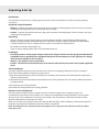
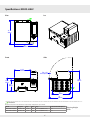
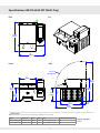
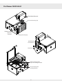
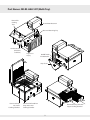
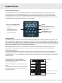
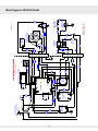
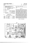
Reservoir Steamer
User Manual
NR-RS-HALF and NR-RS-HALF-MT MODELS
NR-RS-HALF
NR-RS-HALF-MT
Doc no: M0024.11
Revised February 12, 2015
Table of Contents
Cautions & Warnings������������������������������������������������������������������������������������������������� 4
Unpacking & Set Up��������������������������������������������������������������������������������������������������� 5
Specifications:
NR-RS-HALF ��������������������������������������������������������������������������������������������������������������������� 6
NR-RS-HALF-MT (Multi-Tray)������������������������������������������������������������������� 7
Part Names:
NR-RS-HALF ��������������������������������������������������������������������������������������������������������������������� 8
NR-RS-HALF-MT (Multi-Tray)������������������������������������������������������������������� 9
General Information�����������������������������������������������������������������������������������������������10
• Determining Your Salt Quantity
• Loading the Unit
Keyboard & Display�������������������������������������������������������������������������������������������������11
• Using the Keyboard & Display
• Setting the Timer
• Using the Preset Buttons
• Accessing the User Function Menu
Cooking�������������������������������������������������������������������������������������������������������������������������������������12
Cleaning & Maintenance���������������������������������������������������������������������������������13
• Daily Cleaning and Maintenance
• “TIME FOR CLEANING” Message
User Function Menu Descriptions ���������������������������������������������������14
Error Codes���������������������������������������������������������������������������������������������������������������������������15
Troubleshooting ���������������������������������������������������������������������������������������������������������17
• Troubleshooting
• Storage, Service or Transport Preparation
Wire Diagram: 208 VAC Model ���������������������������������������������������������������18
Limited Warranty���������������������������������������������������������������������������������������������������������19
3
Cautions & Warnings
!
WARNING: Please read this entire manual before you install the appliance. Failure to
follow instructions may result in property damage, bodily injury or even death.
For your safety: Do not store gasoline or other flammable vapors and liquids in the
vicinity of this or any other appliance.
WARNING: Improper installation, adjustment, alteration, service or maintenance
can result in property damage, injury or death. Read the installation, operation and
maintenance instructions thoroughly before installing or servicing this equipment.
WARNING: This appliance must be grounded.
CAUTION: All electrical connections must be in accordance with local electrical codes
and any other applicable codes.
This manual contains additional parts information and exploded views
intended only for qualified service technicians.
There are NO user serviceable parts inside this appliance.
An ongoing program of product improvement
may require us to change specifications without
notice. Printed in the U.S.A.
UL 197
ANSI/NSF 4
4
NextRev
1801 W. Bakerview Rd.
Bellingham, WA 98226
844.585.5515 • NextRevcorp.com
Unpacking & Set-Up
Introduction
The Ohmic Reservoir Steamer uses instantly-generated steam to cook or heat food items. It does not require plumbing
connections.
Important Safety Information
•Warning – Indicates information important to the proper operation of the equipment. Failure to observe may result
in damage to the equipment and/or severe bodily injury or death.
•Caution – Indicates information important to the proper operation of the equipment. Failure to observe may result
in damage to the equipment.
Unpacking
• Unpack. Contents include: Steamer with cord and plug (208 and 240 VAC models: NEMA 6-20), BPA-free high
temperature polypropylene Plastic Water Reservoir, Third-Size Solid Pan to collect condensate from beneath the
Cooking Chamber, Drip Tray for condensate from raised cover and Half-Size Perforated Pan.
MT model also includes 2 Removable Trays.
• Clean to remove shipping debris. Rinse out Plastic Water Reservoir.
Installation
• Check data plate on unit for proper voltage requirement. Plug the Steamer into the appropriate 20A, 208 VAC
or 240 VAC circuit as specified on the equipment data plate. Do not attempt to run this appliance at a voltage
other than that specified on the data plate.
• Warning – This appliance must be grounded.
• Caution – All electrical connections must be in accordance with local electrical codes and any other applicable
codes.
Set Up Equipment
Unit ships assembled, however some parts below may come loose in shipping. These parts will also routinely be
removed for cleaning. Refer to diagrams on pages 8 and 9.
1. Align Drip Chute with keyhole slots onto the posts on Steamer back and secure. This chute channels condensation
into the Condensate Pan.
2. Slide Third-size Solid (Condensate) Pan beneath the Lower Cooking Chamber. This pan catches condensate from the
Cooking Chamber.
3. Place Pan Insert in Cooking Chamber.
4. Place Half-Size Perforated Pan into Cooking Chamber.
Determine “Your Salt Quantity”
The Steam Reservoir depends upon a specific amount of salt in the supply water to operate properly. Salt
concentrations in tap water vary by location, so it is necessary to determine the salt concentration at your location.
The amount of salt you determine is correct for your location, “Your Salt Quantity”, will be the amount you add to
the Plastic Water Reservoir each time you refill it.
When you turn the unit on for the first time, the message “RUN SALINITY CHECK” will display. Follow the procedure on
page 10 to run the check and determine how much salt you should add.
Note: Standard table salt is required to obtain the proper result. Large grain salts or flake salts will not achieve
the proper result.
5
7' CordPERMISSION
with NemaOF
5-20
Plug
ANY REPRODUCTION OR USE IN PART OR AS A WHOLE WITHOUT THE WRITTEN
WOOD
STONE
IS PROHIBITE
7' Cord
with
Nema 5-2
THE INFORMATION CONTAINED IN THIS DRAWING IS THE SOLE PROPERTY OF WOOD STONE CORPORAT
Cord Receptacle
ANY REPRODUCTION OR USE IN PART OR AS A WHOLE WITHOUT THE WRITTENPower
PERMISSION
OF WOOD STONE IS
IEC 320 Inlet Receptacle
7' Cord with
Nema
5-20
Plug
Power
Cord
Receptac
IEC 320 Inlet Recepta
7' Cord with Nema 5-
Specifications: NR-RS-HALF
Iso
Plan
19"
480mm
19"
480mm
19"
480mm
19"
480mm
19"
480mm
19"
480mm
19"
480mm
Front
Side
12 3/4"
320mm
12 3/4"
320mm
Path of Lid
When Opened
12 3/4"
320mm
12 3/4"
320mm
Path of Lid
When Opened
Path of Lid
When Opened
Path of Lid
When Opened
10 1/2"
270mm
16 1/2"
420mm
9 1/4"
240mm
m
10 1/2"
270mm
1
4
16 1/2"
420mm
1
4
9 10
1/4"1/2"
270mm
240mm
15"
380mm
9 1/4"
240mm
19"
480mm
Electrical
Check the data plate on the Steamer to verify voltage configuration of your model.
15"
380mm
19"
480mm
15"
380mm
15"
19"
380mm
480mm
19"
480mm
Shipping
of 1
SHEET: 1 Weight
of ongoing
product improvement
may require
us to may require us to
An
program of product
improvement
Model
Voltage/hz
Amps
Watts Plug
Dedicated Circuit Required
s without
notice.
change
specifications
without notice.
PART
#:
SHEET: 1 of 1
PART
#:
WSI-RS-1/2-208-MT
WSI-RS-1/2-208-MT
NR-RS-HALF-208-MT
60IN
Hz INCHES
13.5 A
2800 20 A cord (NEMA 6-20P)
20 A
MENSIONS
ARE DIMENSIONS
IN INCHES208 VAC,
ARE
50 lbs
S: LINEAR
±1/2 [±10mm],
ANGULAR
±2°
TOLERANCES:
LINEAR
[±10mm],
NR-RS-HALF-240-MT
240±1/2
VAC, 60
Hz
13.5ANGULAR
A DATE:
3240 ±2°
20 A cord (NEMA
6-20P)
20 A
bena
DATE:
10/22/2014
DWN
BY:
oing program
of OTHERWISE
product
improvement
may
require
us
to
10/22/2014
DWN
BY: bena
NLESS
NOTED
UNLESS NOTED OTHERWISE
specifications without notice.
PART #: WSI-RS-1/2-208-MT
SHEET: 1 of 1
An ongoingDIMENSIONS
program of product
may require us to
ARE INimprovement
INCHES
6
change
specifications
without
notice.
OLERANCES: LINEAR ±1/2 [±10mm], ANGULAR ±2°
#: WSI-RS-1/2-208-MT DWN BY:SHEET:
bena 1 of 1
DATE: PART
10/22/2014
DIMENSIONS
ARE IN INCHES
UNLESS
NOTED OTHERWISE
50-1111 www.woodstone-corp.com
Bellingham,
WA 360/650-1111
www.woodstone-corp.com
208 V Multi-Tray
208 V Multi-Tray
General Arrangement
General Arrangement
REV:
2
REV
2
THE INFORMATION CONTAINED IN THIS DRAWING IS THE SOLE PROPERTY OF WOOD STONE CORPORATION
ANY REPRODUCTION OR USE IN PART OR AS A WHOLE WITHOUT THE WRITTEN PERMISSION OF WOOD STONE IS PROH
Specifications: NR-RS-HALF-MT (Multi-Tray)
Plan
Power Cord Receptacle
IEC 320 Inlet Receptacle
7' Cord with Nema 5-20 Plu
Iso
20 1/2"
20 1/2"
520mm
520mm
20 1/2"
520mm
20 1/2"
520mm
19"
19"
480mm
480mm
19"
480mm
Front
Side
19"
480mm
Path of Lid
When Opened
Path of Lid
Path
of Lid
When
Opened
When Opened
13"
13"
330mm
330mm
13"
330mm
28 1/4"
720mm
Path of Lid
When Opened
12 1/2"
12 1/2"
320mm
320mm
12 1/2"
320mm
9 1/4"
9 1/4"
240mm
240mm
9 1/4"
240mm
13"
330mm
9 3/4"
9 3/4"
250mm
250mm
9 3/4"
250mm
12 1/2"
320mm
9 3/4"
250mm
9 1/4"
240mm
16 1/2
16 1/2
420mm
420mm
16 1/2"
420mm
28 1/4"
720mm
15"
380mm
20 1/4"
510mm
15"
15"
380mm
380mm
20 1/4"
20
1/4"
510mm
510mm
3 1/4"
80mm
3 1/4"
3 1/4"
16 1/2" 80mm
420mm 80mm
Electrical
Check
the dataofplate
on theimprovement
Steamer to verifymay
voltage
configuration
An ongoing
program
product
require
us to of your model.
g program
of product
improvement
require usmay
to require us to
An ongoing
program
of productmay
improvement
change specifications
withoutVoltage/hz
notice.
3 1/4"
15"
Model
Amps
Watts
Plug
Dedicated Circuit Required
ecifications
notice. without notice.
changewithout
specifications
PART #: WSI-RS-1/2-208-MT
SHEET: 1 of 1 80mm
380mm
PART
#:
DIMENSIONS ARE IN INCHES
PART
#:
SHEET:
1
of
1
WSI-RS-1/2-208-MT
SHEET:
1
of
1
WSI-RS-1/2-208-MT
Shipping Weight
DIMENSIONS
ARE
IN INCHES
DIMENSIONS
ARE60IN
NR-RS-HALF-208-MT
208 VAC,
HzINCHES
13.5 A
2800 20 A cord (NEMA 6-20P)
20 A
20 1/4"
TOLERANCES:
LINEAR
±1/2 [±10mm],
ANGULAR
±2°
DATE:
ERANCES:TOLERANCES:
LINEAR
±1/2
[±10mm],
ANGULAR
±2°
LINEAR
±1/2
[±10mm],
ANGULAR
±2°
61 lbs
2/11/2015
DWN
BY: bena
510mm
NR-RS-HALF-240-MT
240 VAC,OTHERWISE
60 Hz
13.5 A
3240
cord (NEMA
20 A
benaDWN
DATE:20 A2/11/2015
UNLESS NOTED
DATE:6-20P)2/11/2015
DWN BY:
BY: bena
UNLESS NOTED
OTHERWISE
UNLESS
NOTED OTHERWISE
WAwww.woodstone-corp.com
360/650-1111 www.woodstone-corp.com
WA Bellingham,
360/650-1111
Bellingham,
www.woodstone-corp.com
ngoing
programWA
of 360/650-1111
product improvement
may require us to
7
208
208 V Multi-Tray
208 V
V Multi-Tray
Multi-Tray
Arrangement
General General
Arrangement
General
Arrangement
REV:
2
Part Names: NR-RS-HALF
Plastic Water Reservoir
Reservoir Receiving Cup
Condensate Pan
(Third-Size
Solid Pan)
Keypad and Display
On/Off Switch
Circuit Breaker
Drip Chute
SHEET: 1 of 1
THE INFORMATION CONTAINED IN THIS DRAWING IS THE SOLE PROPERTY OF WOOD STONE CORPORATION
Y REPRODUCTION OR USE IN PART OR AS A WHOLE WITHOUT THE WRITTEN PERMISSION OF WOOD STONE IS PROHIBITED
DWN BY: bena
1 of 1
Half-Size PerforatedSHEET:
Pan
into Cooking
Chamber
PART
#: WSI-RS-1/2-208-MT
THE INFORMATION CONTAINED IN THIS DRAWING IS THE SOLE PROPERTY OF WOOD STONEdrops
CORPORATION
Alternate Views
208 V Multi-Tray
Alternate Views
208 V Multi-Tray
NY REPRODUCTION OR USE IN PART OR AS A WHOLE WITHOUT THE WRITTEN PERMISSION OF WOOD STONE IS PROHIBITED
Pan Insert drops into
Cooking Chamber DATE:
8
An ongoing program of product improvement may require us to
DWN BY: bena
DATE:
PART #: 10/22/2014
WSI-RS-1/2-208-MT
10/22/2014
REV:
3
3
REV:
Part Names: NR-RS-HALF-MT (Multi-Tray)
Removable
Cooking
Trays
Plastic Water Reservoir
Reservoir Receiving Cup
Condensate Pan
(Third-Size
Solid Pan)
Keypad and
Display
On/Off Switch
Circuit Breaker
Drip Chute
uire us to
SHEET: 1 of 1
R ±2°
THE INFORMATION CONTAINED IN THIS DRAWING IS THE SOLE PROPERTY OF WOOD STONE CORPORATION
ANY REPRODUCTION OR USE IN PART OR AS A WHOLE WITHOUT THE WRITTEN PERMISSION OF WOOD STONE IS PROHIBITED
2
PART #: WSI-RS-1/2-208-MT
Alternate Views
208 V Multi-Tray
Pan Insert drops
into Lower
Cooking Chamber
DWN BY: bena
REV
DATE: 10/22/2014
Half-Size Perforated Pan
drops into Lower
Cooking Chamber
Removable Trays slide into
Upper Cooking Chamber
o
us to
9
An ongoing program of product improvement may require us to
THE INFORMATION CONTAINED IN THIS DRAWING IS THE SOLE PROPERTY OF WOOD STONE CORPORATION
change specifications without notice.
SHEET: 1 of 1
SHEET: 1 of 1
DWN BY: bena
REV:
REV:
General Information
Determining Your Salt Quantity
The Steam Reservoir depends upon a specific amount of salt in the supply water to operate properly. Salt
concentrations in tap water vary by location, so it is necessary to determine the salt concentration at your specific
location. To determine Your Salt Quantity, follow the procedure below. This quantity, displayed at the end of the
procedure, is the amount of salt you’ll add to the Plastic Water Reservoir each time you refill it. This procedure only
needs to be done once. Afterwards, Your Salt Quantity will be displayed each time the Steamer is powered ON.
Note: Standard table salt is required to obtain the proper result. Do not use large grain or flake salt.
Running a Salinity Check
1. Fill the Plastic Water Reservoir to the top with tap water. Do not add salt.
2. Replace cap on Reservoir, and Reservoir onto Steamer. Turn on Steamer using the On/Off Switch on the back.
3. Wait for display to read “00.00”.
4. Press and hold down the Start/Stop button while the display reads “00.00” until a second beep sounds–
approximately 5 seconds.
5. “SALINITY CHECK” will appear as the first item.
6. Press the Start/Stop button to select “SALINITY CHECK”. The display will change to “CHECKING”.
7. After about 1 minute, the display will read the amount of salt to add to the Plastic Water Reservoir each time it is
filled. It is Your Salt Quantity—the amount of salt you should add based upon your location. Note: This quantity will
appear on the display each time the Steamer is turned ON (right after the number of minutes until next cleaning
appears).
8. To continue the Cooking process, see page 12.
Loading the Unit
• Using a Half-Size Perforated Pan for cooking allows steam to reach the food efficiently. However, some products, like
rice, must be cooked in a Half-Size Solid Pan (not provided).
• If equipped with the multi-tray (-MT) option, food is placed into the Removable Trays. If desired, instead of using the
trays, you may place foods into the Half-Size Pan below the trays. When operated in this manner, the Removable Trays
must be remain in place during the cooking process. DO NOT cook foods in the Removable Trays and the Half-Size
Pan at the same time. Attempting to cook foods in both simultaneously will result in much longer cook times and
flavor transfer between food items.
10
Keypad & Display
Using the Keypad & Display
Using the keypad buttons, you can set a cooking time (see “Setting the Timer below), create pre-stored “favorite”
cooking times (see “Using the Preset Buttons below), and access maintenance functions (see “Accessing the User
Function Menu” below). You can find descriptions of these maintenance User Functions on page 14 of this manual.
The display shows the cooking time, maintenance functions, and error messages describing the status of the unit. Error
message descriptions can be found on pages 15–16 of this manual.
Pressing the Start/Stop button:
Display
• Starts cook when timer is set
Down/Up arrows increase or
decrease cook times and scroll
through menus
• Stops cook
• Selects the displayed
menu item while in the
User Function Menu
Preset buttons to store
favorite timer settings
Setting the Timer
The timer displays the cook time in minutes and seconds. It can be set at 15 second increments using the Up and
Down arrow buttons. Maximum time is 99 minutes, 30 seconds. Timer defaults to “00:00”. During cooking cycle,
timer counts down to 00.00 by seconds. At “00.00”, a beep sounds 5 times. At any point during a cook, the operator
can increase or decrease cook time in 15 second increments using the Up or Down arrows, except during a stored
timed cycle, where the cycle can be stopped, but not modified.
Tip: Holding down the Up or Down arrow button for 5 seconds will increment the timer by minutes instead of 15
second intervals. Releasing the Up or down arrow button and re-pressing will revert back to 15 second intervals.
Using the Preset Buttons
The keypad includes four numbered Preset buttons for stored timer settings. To store or change a setting, set the
time display to the desired time using the Up and Down arrows as described above. Then press and hold the desired
numbered button (1, 2, 3 or 4) until it beeps to assign the timer setting to that button. Pressing the button activates the
stored cook time.
Accessing the User Function Menu
Salinity Check
While the display reads “00.00”, hold Start/Stop
button until beep (~5 sec.).
Drain
Use the Down/Up arrows to scroll through menu
items.
Flush
Press the Start/Stop button to select the displayed
menu item. User Function menu descriptions can
be found on page 14.
Clean
Display Clean Hours Set Point
Exits User Function Menu
11
Cooking
Prepare to Cook
• Remove the Plastic Water Reservoir from the unit and unscrew cap from bottom of Plastic Water Reservoir. Add
Your Salt Quantity to the reservoir. Note: Standard table salt is required to obtain the appropriate amount of
salt. (See page 10 if you haven’t determined Your Salt Quantity.) Completely fill the reservoir with ordinary tap water.
Screw the cap back on to the reservoir. Shake to disperse the salt.
Warning – Adding more salt to the reservoir than indicated can damage the unit.
• Place the Plastic Water Reservoir on the Steamer’s top, right side. The Reservoir Cap should fit easily into the Reservoir
Receiving Cup. Once properly placed, water will flow into the Steamer as needed.
• Verify the Condensate Pan is in place under the Steamer, and the Drip is installed at the back of the Steamer.
• Place Half-Size Perforated Pan into Lower Cooking Chamber.
For -MT models: Removable Trays and the Half-Size Perforated Pan are available for cooks. Either can be used, but not
both simultaneously. While cooking, always have both Pan and Tray in the Steamer, no matter which actually holds
product.
Note: Verify the Pan Insert is placed beneath the Half-Sized Pan in the Cooking Chamber.
• Turn Steamer on with On/Off Switch on rear right of unit.
Note: Steamer may be left on so that it is always ready to use. From cold start it will require a single empty cook cycle for
approximately three minutes to pre-heat.
Cooking
• Warning – Surfaces of Steamer may be hot to the touch.
• Place food in Pan or Tray(s) in the Cooking Chamber. (See “Loading the Unit” on page 10.)
• Set a cook time on the timer (see “Setting the Time on page 11) and press Stop/Start button, or select a Preset button.
(See “Using the Preset Buttons” on page 11.)
• Unit will beep five times when timer has counted down from the starting cook time to “00.00”.
• Open cover and remove food. Warning – To avoid injury, be careful when opening top cover. Be sure to allow
steam to escape before putting hands or face over the Steamer.
• Periodically check Condensate Pan—empty as necessary and replace into unit. It is okay to empty and replace while
Steamer is running.
Cooking Notes
• If a cook is longer than 30 minutes, every 15 minutes there will be a 3 second drain that results in a 10–20 second
steam pause. This is expected.
• Prior to a cook starting, pressing the Start/Stop button 2 times quickly will reset the timer display to read “00:00”.
• After a cook has started, pressing the Start/Stop button once will immediately stop the cook. “STOPPING” will display
for 10 seconds, then the display timer will return to “00.00”.
• It is important to keep the On/Off Switch ON during a cook cycle. If there is a need to turn the On/Off Switch OFF, first
press the Start/Stop button, allow the 10 second Stop cycle to complete, then turn off the power.
If the power is turned off during a cook cycle, it will not harm the Steamer, but the next time the unit is turned ON, it
will take longer for the unit to reach steam production.
12
Cleaning & Maintenance
Daily Cleaning and Maintenance
1. Turn Steamer off at the right rear On/Off Switch and unplug unit from wall.
2. Allow Steamer to cool.
3. Remove Cooking Pans and/or Cooking Trays and wash them.
4. Wipe inside of Cooking Chamber chamber and underside of chamber lid.
For -MT models: Wipe inside of Upper & Lower Cooking Chambers and underside of chamber lid.
5. Remove and empty Condensate Pan underneath Steamer and Drip Chute at rear of Steamer. Rinse and replace.
Note: Salted water can remain for next day’s use. Occasionally, the Plastic Water Reservoir and its screw cap should be
rinsed out.
Periodic Maintenance
Time for Cleaning
After 72 hours, the unit will alert the user when cleaning with Durgol® Swiss Expresso or Durgol Universal Express
is required by flashing back and forth between “TIME FOR CLEANING” and “00:00” during an idle state (i.e. when the
cooking timer reads “00:00”). The unit can still run without cleaning after this message appears. However, it is very
important to run the CLEAN function as soon as possible. The CLEAN function takes about 2 hours.
IMPORTANT: Do not turn off the unit during the cleaning process. Cooking cannot continue until a clean has been
completed. Doing so will not harm the unit, but upon start up, the system will start the cleaning cycle again from
where it left off in order to protect the unit.
Running the Clean Cycle
1. Remove the Water Reservoir. If more than half full, you have enough water to continue without refilling. If it is less
than half full, empty and refill as if for normal operation (with tap water and Your Salt Quantity). Screw on cap and
set aside.
2. Empty the Condensate Pan and replace under unit.
3. Select the “CLEAN” cycle from the User Function Menu (see page 11). The display will read “REMOVE RESERVOIR
THEN PRESS START”.
4. With the Reservoir off the unit, press the START/STOP button. Note: Once the cleaning process starts do not shut off
the steamer.
5. Display will read “CLEANING” while the unit drains the water from the Reservoir Receiving Cup. DO NOT add Durgol
during yet.
6. Remove cap from the Durgol® Swiss Espresso cleaning agent so it’s ready to pour.
7. When the display changes to “PRESS START THEN ADD CLEANER”, press Start/Stop. The display will read “PUMPING”
for 60 seconds. During this time, carefully add the entire 4.2 oz bottle of Durgol (or 1/2 cup if dispensing from larger
container) to the Reservoir Receiving Cup as the liquid level allows. Be careful not to overflow the cup.
8. The unit will automatically start a 100-minute countdown. “CLEANING” will display every 15 seconds.
9. Place the prepared Water Reservoir (containing salted water) in place on the unit.
10. The unit proceeds unassisted through the following cleaning steps:
a. Cleaning agent: 100 minutes—display shows countdown timer, with “CLEANING” every 15 seconds.
b. Removal of cleaning agent: 6-1/2 minutes—display will read “CLEANING”, then “DRAINING”.
c. Steam clean: 5 minutes—display shows countdown timer. Caution: Steamer is hot during this phase.
11. Upon completion the unit will beep and the display will read “CLEANING COMPLETE”.
12. Empty, rinse, and replace the Condensate Pan. The unit is now ready to resume normal operation.
13
User Function Menu Descriptions
User Function Menu, v6.0.4
To enter the User Function Menu, hold the Start/Stop button until the beep sounds (about 5 seconds) and then
release. Use the Up and Down buttons to scroll between menu items. Press the Start/Stop button to select the function
displayed. User Function Menu item descriptions follow.
Salinity Check
Selecting “SALINITY CHECK” checks the salinity of the water in the Plastic Water Reservoir. (See the “Determining
‘Your Salt Quantity’ ” section on page 10 for the Salinity Check procedure.) While running the salinity check, the unit
will display “CHECKING”. Upon completion, the amount of salt needed to bring the water to the required level will be
displayed. For example, if no salt was needed, the display would read “0 TSP”. If 1/4 tsp. of salt was needed, the display
would read “1/4 TSP” and you would add 1/4 level teaspoon of standard table salt (do not use large grain or flake salt).
This quantity will appear on the display each time the Steamer is turned ON.
Note: The SALINITY CHECK function will only give accurate readings when the unit is first turned on using the On/Off
Switch. The salinity check will not be accurate when the unit is hot.
Drain
The Drain function will open the drain of the steam generator within the unit (it does not affect the Plastic Water
Reservoir). During this time, the screen will display “DRAINING”. Upon release, the unit will beep twice and return to the
cooking timer.
Flush
The FLUSH function will turn on the pump for 40 seconds, drawing water into the steam generator. During this time, the
screen will scroll “FLUSHING”. The unit will then enter a Drain function—the display will read “DRAINING”. Upon release,
the unit will beep twice and return to the cooking timer.
Clean
Selecting the Clean cycle function will run a cleaning cycle on the unit. To run the Clean cycle function, follow the “TIME
FOR CLEANING” procedure on page 13.
Display Clean Hours Set Point
This function displays the number of hours the Steamer is programmed to run before the “TIME FOR CLEANING”
message is displayed.
Return
Selecting exits the User Function Menu.
14
Error Codes
Maintenance Error Codes
The following error codes require simple maintenance action on the part of the user to restore the unit to working
condition.
Error 1
The unit will beep and the display will read “ERROR 1” when the water in the steam generator is too electrically
conductive. This is caused by the addition of too much salt.
To clear the error: Follow the “Flushing the System with Clean Water” procedure described below. Repeat the
procedure if the ERROR 1 message is displayed again. If ERROR 1 is received 3 times in a row, call the Service
Department toll-free at 844-585-5515.
Flushing the System with Clean Water
Use this procedure when the water is too salty. Too much salt will cause the “ERROR 1” message to appear, or the circuit
breaker to trip repeatedly.
1. Remove the Plastic Water Reservoir and rinse it out. Refill with tap water only–no salt.
2. Replace the Plastic Water Reservoir on the Steamer.
3. Press and hold the Start/Stop button for 5 seconds until a beep is heard. Using the Up and Down arrow buttons,
scroll to “FLUSH”.
4. Press the Start/Stop button again to begin the Flush cycle. This will run the pump for 40 seconds to fill the steam
generator with clean water. Some water may flow through into the cooking compartment.
5. After 30 seconds, the display will scroll “DRAINING”.
6. Wait for the unit to beep and the display to return to the cooking timer.
7. Remove the Plastic Water Reservoir, add Your Salt Quantity to the reservoir, refill with tap water to top, shake to
disperse salt and replace on Steamer. Unit is ready to cook.
Water Error
The unit will beep and display “WATER ERROR” on the screen when the water in the reservoir is not sufficiently
electrically conductive, or if there is no water left in the reservoir.
To clear the error: Refill the reservoir with properly salted water, shake and return to Steamer. Then press the
Start/Stop button. The unit will return to the cooking timer and cook the remainder of the time specified in the
cook.
Warning – Adding more salt to the reservoir than indicated can damage the unit.
15
Error Codes
Service-Related Error Codes
The following error codes indicate more complex technical problems and will require a call to a qualified service
technician.
Contact the Service Department toll free at 844.585.5515.
Temperature Fault
This message is displayed if the electronics compartment temperature is above the maximum operating temperature.
The unit will remain on, but not function. Turn off the unit and call for service.
Ground Fault
This message is displayed if the unit is not properly grounded, either internally or at the outlet socket. Ensure the unit is
plugged into a grounded outlet. If problem persists, turn off the unit and call for service.
Fan Fault
This message is displayed when a faulty electrical condition is detected when the fan should turn on. “FAN FAULT” will
display every 5 seconds. The unit will continue to operate for a short period of time until the electronics compartment
temperature exceeds its maximum operating temperature, resulting in a Temperature Fault message (see above). Turn
off the unit as soon as possible and call for service.
12V Fault
This message is displayed when a faulty electrical condition has been detected in the 12V system on the control board
has been detected. “12V FAULT” will display every 10 seconds. The unit will continue to operate, but cook quality may be
affected. Note code and call for service.
24V Fault
This message is displayed when a faulty electrical condition has been detected in the 24V system on the control board
has been detected. “24V FAULT” will display every 10 seconds. The unit will continue to operate, but cook quality may be
affected. Note code and call for service.
16
Troubleshooting
Troubleshooting
Symptom
Steamer does not turn ON
Solution
Check that the power cord is plugged into a functioning outlet.
Check that the circuit breaker on the back of the Steamer has not
tripped. If breaker has tripped, push to reset. If breaker continues to
trip, contact the Service Department toll free at 844.585.5515.
Display reads “ERROR 1”
Water in the Plastic Water Reservoir is too salty. Follow the “Flushing
the System with Clean Water” procedure on page 15.
Display reads “WATER ERROR”,
accompanied by a beep.
Steamer out of water OR water doesn’t contain enough salt.
Remove and empty the Plastic Water Reservoir. Add Your Salt Quantity
to the empty reservoir, making certain to use standard table salt. Refill
with tap water to top, shake to disperse salt and replace on Steamer.
Unit is ready to cook.
Salt other than standard table salt was used to salt water. Note: The
density of different types of salt varies greatly and may negatively
effect concentration. Standard table salt is required to obtain the
proper result. Do not use large grain or flake salt.
Water overflows from the Plastic
Water Reservoir
Check reservoir cap (p/n 7000-1243). Replace if leaking or damaged.
Inspect plastic reservoir for cracks or punctures (p/n 5810-0205).
Circuit breaker trips
Allow the Steamer to cool for approximately two minutes. Push the
circuit breaker button in to reset.
Note: The circuit breaker is on the back
of the Steamer, below the Power Switch.
When tripped, the normally all black
circuit breaker will be partially white.
The circuit breaker may continue to trip if the cause is too much salt in
the water. Follow the “Flushing the Steam Generator with Clean Water”
procedure on page 15.
If the circuit breaker trips again, contact the Service Department toll
free at 844-585-5515.
There are no user serviceable parts inside this appliance. If the unit is not working properly after going through
the above troubleshooting items, contact the Service Department toll free at 844.585.5515.
To prepare the Reservoir Steamer for storage, service or transport
1. Remove the Plastic Water Reservoir and rinse it out.
2. Press and hold the Start/Stop button for 5 seconds until a beep is heard. Using the Up and Down arrow buttons,
scroll to “FLUSH”.
3. Press the Start/Stop button again to begin the Flush cycle. This will run the pump for 40 seconds until the remaining
water is gone. Some water may flow through into the cooking compartment.
4. After 30 seconds, the display will scroll “DRAINING”.
5. Wait for the unit to beep and the display to return to the cooking timer.
6. Turn off unit, unplug and thoroughly wipe dry.
17
R
LD
Blue
GROUND
DETECTOR
BK
LN
Red
Black
Yellow
Black/Red
+
White
*CAP unused wires
Wood Stone Ideas
www.woodstoneideas.com
GND
LN
W
2
LD
RIBBON
CABLE
Y
4
BK
+3
25 A SOLID
STATE RELAY
R-Y
To User
Interface
Board
BU
DIODE
1
OR
BR
BK
+N POWER
1
P1
8 6
P2
4 2
DPST
RELAY
R-W
CURRENT
SENSOR
+
Power Relay
SSR
+
+
PUMP
+ DRAIN+
FAN
CONTROLLER
PROG
1
+
RIBBON
CABLE
GND
SENSE
To
Controller
1
R
R
BK
BK
2
USER INTERFACE BOARD
BK
R
W-BU
BK
BK
WSI-RS-1/2-208
BK-W
OR
R-Y
FAN
208V RESERVOIR STEAMER
B
9
8
7
6
5
4
3
2
1
A
9
8
7
6
5
4
3
2
1
Control Box Divider
Orange
120VAC
18
0
TRANSFORMER
R
R
BK
R-Y
BK
BK
2 POLE
SWITCH
L2
L1
R
W
BK
Y
208V, 20A
NEMA 6-20P
16 A CIRCUIT
BREAKER
PUMP
DIAG #: WD502 Rev. 1
DATE: 10/24/2014
BK
W-BU
OHMIC STEAM
GENERATOR
PINCH
VALVE
TERMINAL
BLOCK 1
BR
OR
GN-Y
BK-W
Sheet: 1 of 1
BK
Wire Diagram: 208 VAC Model
Limited Warranty
ALL WARRANTY SERVICE MUST BE PRE-APPROVED BY NextRev.
PLEASE CONTACT THE FACTORY FIRST.
Please call toll free at 844.585.5515. Our normal service hours are 8am to 4:30pm PST Monday through Friday. NextRev
warrants its equipment to the original purchaser against defects in material or manufacture for a period of one year
from the original date of purchase subject to the following exclusions and limitations.
EXCLUSIONS:
THE WARRANTIES PROVIDED BY NEXTREV DO NOT APPLY IN THE FOLLOWING INSTANCES:
1. In the event that the equipment is improperly installed. Proper installation is the responsibility of the installer;
proper installation procedures are prescribed by the NextRev User Manual.
2. In the event the equipment is improperly maintained. Proper maintenance is the responsibility of the user;
proper maintenance procedures are prescribed in the NextRev User Manual.
3. In the event that the failure or malfunction of the appliance or any part thereof is caused by abnormal use or is
otherwise not attributable to defect in material or manufacture.
4. In the event that the appliance, by whatever cause, has been materially altered from the condition in which it
left the factory.
5. In the event that the rating plate has been removed, altered or obliterated.
6. On parts that would be normally worn or replaced under normal conditions.
IF ANY ORAL STATEMENTS HAVE BEEN MADE REGARDING THIS APPLIANCE, SUCH STATEMENTS DO NOT
CONSTITUTE WARRANTIES AND ARE NOT PART OF THE CONTRACT OF SALE. THIS LIMITED WARRANTY
CONSTITUTES THE COMPLETE, FINAL AND EXCLUSIVE STATEMENT WITH REGARD TO WARRANTIES. THIS
LIMITED WARRANTY IS EXCLUSIVE, AND IN LIEU OF, ALL OTHER WARRANTIES WHETHER WRITTEN, ORAL
OR IMPLIED, INCLUDING BUT NOT LIMITED TO, ANY WARRANTY OF MERCHANTABILITY OR FITNESS FOR
PARTICULAR PURPOSE OR WARRANTY AGAINST LATENT DEFECTS.
LIMITATIONS OF LIABILITY:
In the event of warranty claim or otherwise, the sole obligation of NextRev shall be the repair and/or replacement,
at the option of NextRev, of the appliance or component or part thereof. Such repair or replacement shall be at the
expense of NextRev with the exception of travel over 100 miles or two hours, overtime, and holiday charges which shall
be at the expense of the purchaser. Any repair or replacement under this warranty does not constitute an extension of
the original warranty for any period of the appliance or for any component or part thereof. Parts to be replaced under
this warranty will be repaired or replaced at the option of NextRev with new or functionally operative parts. The liability
of NextRev on any claim of any kind, including claims based on warranty, expressed or implied, contract, negligence,
strict liability or any other theories shall be solely and exclusively the repair or replacement of the product as stated
herein, and such liability shall not include, and purchaser specifically renounces any rights to recover, special, incidental,
consequential or other damages of any kind whatsoever, including, but not limited to, injuries to persons or damage to
property, loss of profits or anticipated profits, or loss of use of the product.
TO SECURE WARRANTY SERVICE:
Please contact the Service Department toll free at 844.585.5515 for warranty service.
19