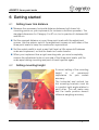
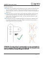
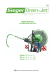
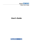
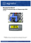
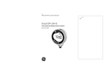
1
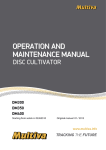
User manual
AGRETO three-point-scale
Weighing indicator B400
06 April 2017
ATTENTION!
ATTENTION Read the operating instructions in this user manual before operating the
equipment for the first time, in order to prevent damage to your scale or implement!
© AGRETO electronics GmbH
AGRETO three-point scale
Table of contents
1
2
3
4
Introduction ........................................................................................................... 3
Scope of delivery .................................................................................................. 3
Intended use ......................................................................................................... 4
Safety .................................................................................................................... 5
4.1
4.2
Safety guidelines for the purchaser ................................................................................ 5
Safety guidelines for operating and assembling personnel ............................................ 5
5
6
Specifications ....................................................................................................... 7
Getting started .................................................................................................... 10
6.1
6.2
6.3
6.4
6.5
6.6
6.7
6.8
Setting lower link distance ............................................................................................ 10
Setting mounting height ................................................................................................ 10
Mounting the three-point scale ..................................................................................... 12
Connecting the weighing indicator ............................................................................... 12
Connecting the distance sensor (if available) ............................................................... 14
Connecting the cable to the signal socket (if available)................................................ 14
Connecting the GPS speed sensor (if available) .......................................................... 15
Connecting the working position sensor (if available) .................................................. 15
7
Weighing indicator .............................................................................................. 16
7.1 Switching on the weighing indicator ............................................................................. 16
7.2 Zeroing .......................................................................................................................... 16
7.3 Standard weighing procedure ...................................................................................... 17
7.4 Weighing with tare function ........................................................................................... 17
7.5 Switching off the weighing indicator ............................................................................. 17
7.6 Settings for displaying the spread rate/ha .................................................................... 18
7.7 Calculating the spread rate ........................................................................................... 20
7.8 General settings ............................................................................................................ 23
7.9 Calibration ..................................................................................................................... 23
7.10
Summing function ..................................................................................................... 25
7.10.1 Setting the summing function .................................................................................... 25
7.10.2 Performing a summation ........................................................................................... 26
7.10.3 Retrieving the sum ..................................................................................................... 26
7.10.4 Deleting the sum ....................................................................................................... 26
7.11
Error messages ......................................................................................................... 27
8
9
10
11
12
13
Troubleshooting .................................................................................................. 28
Maintenance and cleaning ................................................................................. 30
Warranty ............................................................................................................. 30
Declaration of conformity ................................................................................... 31
Disposal .............................................................................................................. 32
Contact information ............................................................................................ 32
© AGRETO electronics GmbH
page:
page:2
AGRETO three-point scale
1 Introduction
Thank you very much for choosing the AGRETO three-point scale. You have just
purchased a robust tool for everyday use.
The AGRETO three-point scale can only be employed as a checkweigher for
internal use. It's not allowed to be used for legal transactions.
Please read this manual carefully before putting the scale to use.
As in common parlance, the word 'load' is used instead of 'mass' in this user
manual.
2 Scope of delivery
Standard scope of delivery
Steel construction with built-in load cells
2 top link brackets with 160 mm hole spacing
2 top link brackets with 130 mm hole spacing
1 top link and 2 lower link pins with linchpins
Weighing indicator with connecting cables
This user manual
Optional accessories:
Lower link hook (instead of ball ends/connection eyes)
3, 5 or 10 m extension cable for the weighing signal
Two-line B400 weighing indicator with distance sensor (instead of the
standard single-line B300 weighing indicator)
Connecting cable to the signal socket for the speed signal (only in
combination with the B400 weighing indicator)
GPS speed sensor for the speed signal (only in combination with the B400
weighing indicator)
© AGRETO electronics GmbH
page:
page:3
AGRETO three-point scale
3 Intended use
The AGRETO three-point scale is a scale for weighing three-point implements
and/or their loads. It's mounted at the three-point linkage between tractor and
implement.
Tractors with Category II and III top links and lower links are suitable, but only
Category II implements can be attached.
Only implements with a total weight of 6,000 kg can be attached.
The scale must be set to the exact same mounting height as the attached
implement.
The implement can only be connected to the scale via the two lower link pins
and the top link pins.
No significant push/pull forces must be transferred, which means that soil tillage
implements can be attached. Seed drills with normal sowing coulters are
acceptable.
The weighing procedure can be performed during standstill or whilst driving.
Three-point scales aren't officially calibratable and therefore not authorized to
determine weights for legal transactions. The scale is meant exclusively as a
checkweigher for internal use.
© AGRETO electronics GmbH
page:
page:4
AGRETO three-point scale
4 Safety
4.1
Safety guidelines for the purchaser
IMPORTANT!
Make sure that every person who works with the AGRETO threepoint scale for the first time, has read and understood this user
manual.
4.2
Safety guidelines for operating and assembling personnel
Appropriate equipment must be used when employing lifting
machinery for transport.
Persons who are involved with mounting, removing or setting up
the three-point scale, must wear safety shoes.
Persons who are involved with mounting, removing or setting up
the three-point scale, must wear safety gloves.
© AGRETO electronics GmbH
page:
page:5
AGRETO three-point scale
During transport the scale or pallet can slip on the vehicle.
Transport and loading personnel must be instructed to securely
attach loads.
Be aware of the risk of crushing between the three-point scale's
moving parts during mounting, removing and setting up.
The scale must not be stored or used in a potentially explosive
environment.
Be careful not to trip over parts or tools that could be lying around
you.
© AGRETO electronics GmbH
page:
page:6
AGRETO three-point scale
5 Specifications
Scale construction
Steel construction with tubes and laser-cut parts
Internal load cells
Roller supported mounting for implement attachment
Designed for implements with a total weight of 6,000 kg
Lower link attachment to the tractor: Pins Ø28 mm, 64 mm inner width, for
lower link with CAT II ball end, CAT II hook and ball, or CAT III hook and
CAT II reduction balls
Lower link attachment to the implement: Ball joint Ø28.4mm, 51 mm width
or a CAT II Walterscheid quick coupling-hook
Lower link distance: CAT II, standard 87.5 cm, can be adjusted infinitely
between 85 and 90 cm with set screws, can be adjusted manually up to
105 cm for attachment to a rigid axle
Top link attachment to the tractor: Pins Ø25.4 mm, 64 mm inner width, for
top links with CAT II ball joint, or CAT II hook and ball
Top link attachment to the implement: CAT II mounting brackets Ø26 mm
Distance lower link-top link on the attachment: infinitely adjustable between
48 and 68 cm
Horizontal distance lower link pins-implement pins (lower link shifted
backwards): 160 mm (200 mm for hooks)
Horizontal distance top link pins-implement pins (top link shifted
backwards): 130 mm or 160 mm depending on the mounting brackets
Net weight approx. 80 kg including pins
Dimensions: 104x84x20 cm (LxWxH, lying down)
© AGRETO electronics GmbH
page:
page:7
AGRETO three-point scale
Load cells
2 high resolution shear force load cells, each at 5,000 kg, 3mV/V, 350 Ohm
Total nominal load: 10,000 kg
120% overload, 150% breaking load
Protection class IP68 (dust- and waterproof)
Operating temperature: -35 up to +65 °C
Temperature compensated: -10 up to +40 °C
Weighing indicator
6-digit LED-backlit LCD display with 20 mm high digits
12 to 24 Volt power supply
Operating temperature: -10 up to +50 °C
Real-time clock
Tare through the push of a button (zeroing the empty implement)
Shockproof and spraywaterproof
Stabilized indicator for reading while driving
OPTIONAL: Two-line weighing indicator with 30 / 20 mm high digits and
special programming to display the spread rate per hectare
© AGRETO electronics GmbH
page:
page:8
AGRETO three-point scale
Cabling
Internal load cell connection with waterproof box (IP67)
3.5 m long weighing signal cable with special sheathing, from the outlet on
the front of the right frame part to the indicator
Waterproof, threaded plug connector (IP68)
2 m power supply cable with a flexible universal plug (for cigarette lighter
and standard sockets according to DIN EN ISO 4165), with integrated and
replaceable fuse
Accuracy
+/- 0.02% load cell accuracy
+/- 1 to 2% accuracy when operated properly in everyday conditions
5 kg weighing indicator resolution
Readability during standstill or smooth ride: very good
Readability during bumpy ride: sufficient
Deviation when load shifts (front, back, left, right): none when operated
properly
Deviation on slopes: hardly noticeable up to 5%
Deviation when inclined sidewards: hardly noticeable up to 5%
Deviation when not attached vertically: hardly noticeable up to 5%, can be
compensated through calibration
© AGRETO electronics GmbH
page:
page:9
AGRETO three-point scale
6 Getting started
6.1
Setting lower link distance
Measure the necessary horizontal distance between both lower link
mounting points on your implement (for instance a fertilizer spreader). The
standard dimension for Category II is 87 cm, but in practice it's between 86
and 88 cm.
Set the required distance on your three-point scale with the adjustment
screws. Use the exterior nuts of the adjustment screws on both sides of the
three-point scale to keep the construction symmetrical.
Set the scale's width in such a way that there's a little space left between
scale and implement, so that the scale isn't under tension.
When your implement has a rigid mounting axle, you must completely
remove the adjustment nuts on one side of the three-point scale, pull the
scale apart during mounting and push it back together again.
6.2
Setting mounting height
A correct setting of the mounting
height
is
of
paramount
importance for your scale's
accuracy.
The horizontal and vertical top
link mounting brackets must be
in a perfect right angle relative to
each other. This will make sure
that the load's position doesn't
influence weighing accuracy.
© AGRETO electronics GmbH
page:
page:10
AGRETO three-point scale
Proceed as follows:
Measure the necessary vertical distance on your implement between lower
link pins and top link pins. If there are several positions for your top link
and/or lower link, choose a combination where the distance is between 50
and 65 cm.
Determine which of the 4 holes on the three-point scale's vertical top link
brackets must be used for the distance you measured. Loosen the 4
interior nuts of the adjustment screws, set the measured distance, and
tighten the nuts again.
The distance can still be readjusted after the implement is attached, but
first relieve any load from the scale. Slightly loosen the nuts and use a
rubber hammer to shift the brackets.
ATTENTION: The exact setting of mounting height is not only a prerequisite for
accurate weighings. When the angle is not exactly right, the threethree-point scale
and/or your implement could get damaged or deformed.
© AGRETO electronics GmbH
page:
page:11
AGRETO three-point scale
6.3
Mounting the three-point scale
You can choose whether you first want to mount the three-point scale to the
tractor or the implement. When your implement has a rigid axle, you must
first mount the scale to the implement. Of course, the scale can be left
mounted on the implement if it is only used for that implement.
Try to use the three-point scale in a position that is as vertical as possible.
Either use the brackets with 130 mm hole spacing, or the brackets with 160
mm hole spacing. If vertical mounting isn't possible, the scale must be
calibrated to obtain correct results. Deviations are hardly noticeable when
under 5 degrees in comparison to the vertical position.
6.4
Connecting the weighing indicator
Position the weighing indicator in a suitable spot in the vehicle.
Connect the power supply cable. Either use the provided cable or connect
the indicator directly to the electric system. The indicator can be run on a
voltage between 12 and 24 Volt. If during operation the power supply to the
indicator is interrupted, it will remember the scale's zero point, but not a
tare point that might have been set.
Connect the weighing signal cable to the plug on the three-point scale. You
could run the cable along the hydraulic tubes to prevent damage.
© AGRETO electronics GmbH
page:
page:12
AGRETO three-point scale
The weighing signal cable is assigned as follows:
Front view cable socket
on the scale
Number Description
Front view cable plug
on the connecting cable
Function
1
EX -
Supply -
2
EX +
Supply +
3
SI -
Signal -
4
SI +
Signal +
5
6
7
© AGRETO electronics GmbH
page:
page:13
AGRETO three-point scale
6.5
Connecting the distance sensor (if available)
In this variant driving speed is determined by a distance sensor. The sensor has
a blue cap and the cables are marked blue near the plug connectors.
Mount the 4 magnets to the rim of a wheel (or on the front axle for tractors with
rear wheel drive) using the included screws. Make sure the magnets are evenly
distributed.
Mount the blue capped sensor with a flat bar in such a way that the sensor tip
points towards the magnets. Set the distance between sensor and magnets at
5 mm.
As soon as the sensor is correctly installed and connected, the weighing
indicator will display the driving speed in 10 second intervals. To check the
driving speed the working position sensor must be in the working position
(=valve open) or unplugged.
The amount of impulses per 100 m is set in the weighing indicator.
6.6
Connecting the cable to the signal socket (if available)
In this variant driving speed is determined via a connecting cable to a signal
socket. The connecting cable with 4-pole plug is connected to the cable that is
marked blue. The other side is connected to the signal socket.
The weighing indicator displays the driving speed in 10 second intervals. To
check the driving speed the working position sensor must be in the working
position (=valve open) or unplugged.
The amount of impulses per 100 m is set in the weighing indicator.
© AGRETO electronics GmbH
page:
page:14
AGRETO three-point scale
6.7
Connecting the GPS speed sensor (if available)
In this variant driving speed is determined via a gps receiver. The receiver is
positioned on the roof and the 4-pin plug is connected to the cable that is
marked blue.
The weighing indicator displays the driving speed in 10 second intervals. To
check the driving speed the working position sensor must be in the working
position (=valve open) or unplugged.
The amount of impulses per 100 m is set in the weighing indicator.
6.8
Connecting the working position sensor (if available)
The sensor has a red cap and the cables are marked red near the plug
connectors.
The working position sensor tells the weighing indicator whether there is any
output. That way the weighing indicator takes into account that some stretches
are driven in the headland, or that the valves are closed, and stops calculating
total completed area.
Mount the working position sensor near the valve or your implement's volume
adjuster. The sensor must be mounted in such a way that it is positioned in front
of the magnet when closed. The magnet should move away from the sensor
when opened.
When there are separate adjustment mechanisms for the left and right side,
mount the sensor and magnet on the side that opens when spread width is
halved.
© AGRETO electronics GmbH
page:
page:15
AGRETO three-point scale
7 Weighing indicator
7.1
Switching on the weighing indicator
Switch the weighing indicator on with the small button on the far left. The
indicator shows a start-up sequence, followed by the scale's actual load, based
on the most recently set zero point.
The upper, larger line displays the scale's actual load (for instance 865 kg) and
the lower, smaller line displays the spread rate per hectare (for instance 220
kg). Next to that, small digits display the driving speed (for instance 10.8 km/h).
7.2
Zeroing
The [ZERO] button resets the indicator's zero point. Use this function for zeroing
the scale with an attached and raised implement. This puts the zero point on
the implement's empty weight, after which a load's weight can be read directly.
© AGRETO electronics GmbH
page:
page:16
AGRETO three-point scale
7.3
Standard weighing procedure
Load and unload the implement, or use your implement as usual, and the load's
actual weight will be displayed immediately on the weighing indicator. The
indicator is stabilized, which allows you to read the weight while driving.
7.4
Weighing with tare function
The tare-function can be used to determine the amount of material which is
scattered to a part of a field:
Press the [TARE] button at the beginning. The indicator shows 0 and
displays the NET symbol.
Continue with your work, on the display you see the net-weight. This is the
lost weight since the activation of the tare function.
If you want to see the total weight, you can use the [SELECT] key to toggle
between the total weight and the net weight.
Read the net weight at the end of your partial area and return to the total
weight display with the [SELECT] key.
You can repeat this process as often as you like.
7.5
Switching off the weighing indicator
Keep the button on the far left pressed until the weighing indicator switches off.
© AGRETO electronics GmbH
page:
page:17
AGRETO three-point scale
7.6
Settings for displaying the spread rate/ha
The following parameters are responsible for the weighing indicator's
functionality with regards to the spread rate:
SPREAD PULSES 10
Impulse/100m
SPREAD WIDTH 10
Spread width in m
SPREAD UPDATE 10
Interval in seconds
SPREAD RES 10
Resolution
SPREAD INPUT IO1
Sensor input
SPREAD MIN.DSP 50
Indicator minimum quantity
SPREAD PREC COUNTS
Calculation method
The first
first two parameters have to be set by you.
The other parameters have been pre-set in such a way that normal operation is
possible right away.
Proceed as follows to change other relevant settings:
Simultaneously keep the lower buttons on the far right (F3) and far left (the
small one) pressed for 3 seconds.
Wait until the word GEN.OPT appears on the display.
Press the [ZERO] button several times, until SPREAD appears on the
display.
Press the [TARE] button. PULSES appears on the display.
Determine how many impulses the sensor sends per 100 m driven. Either
drive exactly 100 m, count the amount of revolutions and multiply that with
the amount of mounted magnets. Or measure the wheel circumference and
manually calculate the amount.
When you use the adapter cable to the signal socket, you normally have to
enter 406 impulses. According to standard the signal socket sends 13,000
impulses per 100 meter. The electronics in the adapter cable reduces this
by 1/32. In practice many signal sockets do not provide the signal
according to standard, with values varying between 200 and 450. It's best
you enter 400 and synchronize the displayed driving speed with the
tractor's speedometer.
© AGRETO electronics GmbH
page:
page:18
AGRETO three-point scale
To set the amount of impulses you enter the number with the numeric
keypad and confirm by pressing the [OK] button.
By pressing the [TARE] button the next parameter WIDTH appears.
Enter the working width in m with the numeric keypad and confirm by
pressing the [OK] button.
Press the [ZERO] button until it says END on the display.
By pressing the [TARE] button the settings are stored, and the indicator
restarts.
© AGRETO electronics GmbH
page:
page:19
AGRETO three-point scale
7.7
Calculating the spread rate
The quantity applied per hectare can be calculated in two different ways:
Automatic Mode
Automatic mode is already active when the weighing indicator is switched on.
The „A“ symbol appears in the top right of the display.
Press the [F3] button to switch from manual mode to automatic mode.
In automatic mode the weighing indicator calculates average weights for
consecutive intervals. An interval normally lasts 10 seconds and can be
adjusted through the SPREAD_UPDATE parameter (not recommended).
At the end of every interval the difference in weight between the interval's
average weight and the preceding interval's average weight is calculated.
This difference is then set off against the completed area (distance driven x
working width) per interval, and is displayed as kg/ha.
Because automatic mode is always running, you can continuously check the
quantity applied per hectare and the driving speed, without having to operate
the indicator. The quantity applied in kg/ha is only displayed if it exceeds the
value in the SPREAD_MIN.DSP setting.
When you start applying, the indicator is in the middle of an interval. Because of
this the first interval isn't complete and thus useless for calculating the spread
rate. If you press the [F3] button on the weighing indicator, it will immediately
start a new interval. It is therefore recommended to press the [F3] button as
soon as you start the application process, and have already reached the
desired driving speed.
© AGRETO electronics GmbH
page:
page:20
AGRETO three-point scale
Please observe the following when reading the spread rate:
When you start driving, you have to drive three intervals with a constant
driving speed (standard setting is 30 seconds) before an accurate weight
has been calculated. That's because the first interval isn't complete. Unless
the calculation was initiated with the [F3] button.
When spread rates per interval are low, weight fluctuations that necessarily
occur during driving significantly affect the calculated quantity. The
displayed value per hectare will fluctuate a lot, which means you will have
to calculate the average of the displayed values and base decisions on
that. In case of highly fluctuating, meaningless values you should switch to
manual mode.
When the indicator is displaying the quantity applied per hectare while
driving on roads, this is caused by weight fluctuations and can be ignored.
Manual mode
In manual mode you can determine the start and end of calculation intervals
yourself. This allows calculations during a longer period, for instance an entire
field length. With an installed working position sensor, this calculation can even
be extended to cover several field lengths up to an entire field.
Manual mode is started by pressing the [F1] button. The „M“ symbol appears in
the top right of the display. A calculation cycle starts and the scale's actual
weight is stored as the calculation's initial weight.
The calculated result is updated in the pre-set interval. An interval normally lasts
for 10 seconds and can be altered through the SPREAD_UPDATE parameter
(not recommended). The scale's actual weight will then be taken as final weight
and the spread rate per hectare will be shown from the first to the actual
interval.
Pressing the [F2] button starts the calculation at any given time, and displays
the result.
While the calculation continues in the background, the intermediate result is
displayed. The [F2] button can be pressed as often as desired. Every time the
updated quantity will be displayed.
You can press the [F1] button to start, and the [F2] button to read the result
while driving.
© AGRETO electronics GmbH
page:
page:21
AGRETO three-point scale
Also observe the following when working in manual mode:
If you haven't installed a working position sensor, the calculation must be
stopped by pressing the [F2] button when the end of a track has been
reached, or else the U-turn is also recorded and distorts the result. For the
same reason a new cycle must be started at each new track by pressing
the [F1] button.
Maintain a constant speed during the entire calculation period, with the
same settings, to obtain a correct result.
When the driving speed or settings change, a new cycle has to be started
to obtain meaningful average results.
Pressing the [F3] button ends manual mode and the indicator switches back to
automatic mode.
© AGRETO electronics GmbH
page:
page:22
AGRETO three-point scale
7.8
General settings
The weighing indicator contains several adjustable parameters that influence
the system's functioning. Normally these parameters have been pre-set
correctly and only need to be changed in the case of specific requirements.
For use with the AGRETO three-point scale, the weighing indicator's following
parameters differ from default settings:
SCALE BUILD TYPE DUAL.R
(set measurement method)
SCALE BUILD CABLE 4
(load cell connection with 4 cables)
SCALE BUILD CAP1 6000
(maximum load)
SCALE BUILD E1 5
(resolution)
SCALE BUILD CAP2 6000
(maximum load)
SCALE BUILD E2 5
(resolution)
SCALE OPTION FILTER 10
(indicator attenuation)
SCALE OPTION Z.RANGE –20 +20
(zeroing up to 20% of maximum load)
SCALE CAL SPAN 2667
(calibration value at 0.8 mV)
7.9
Calibration
When the AGRETO three-point scale is operated vertically or with a slight slant
forward or backward, the factory-set calibration is correct and the scale is ready
for direct use. If this isn't possible, the weighing indicator must be calibrated,
depending on how the scale is employed. A calibration determines the scale's
accuracy. Perform the following steps only when necessary and with the
greatest care.
Every new calibration replaces the previous calibration, and can be repeated as
often as desired.
Use this method only when you have a load of which you know the exact
weight. It is also important that this load can be placed in the middle of the
implement.
Instead of a load, a charge of fertilizer can also be filled during the calibration
process. The weight of this charge must be known, however, or the tractor and
implement must stand on a scale (weighbridge) during the calibration process.
© AGRETO electronics GmbH
page:
page:23
AGRETO three-point scale
Proceed in the following manner:
Place your vehicle on an even surface.
Put the empty implement in the operating position.
Keep the weighing indicator's buttons on the far right (F3) and left (small
button) pressed simultaneously, until the calibration sequence starts.
Wait until the word GEN.OPT appears on the display.
Press the [ZERO] button twice. SCALE appears on the display.
Press the [TARE] button 3x. CAL appears on the display.
Press the [GROSS/NET] button. ZERO appears on the display.
Press the [OK] button twice. “Z in P” appears on the lower line. The zero
point is now defined. Wait until it says “Done” on the lower line.
Press the [OK] button. ZERO appears on the display.
Press the [GROSS/NET] button. SPAN appears on the display.
Press the [OK] button twice.
Now put a load on the scale of which you know the weight, or fill your
implement with a known amount of material. The weight should be as large
as possible, completely filling your implement would be best.
To prevent tensions in the implement and scale from influencing the
calibration, drive forwards and backwards again.
Change the displayed number to the actual weight of the load that was
filled in, by entering it with the numeric keypad.
Press the [OK] button. S.inP appears on the display. The calibration will
now be executed. Wait until it says „Done“ on the lower line.
Press the [OK] button. SPAN appears on the display.
Press the [ZERO] button until it says END on the display.
Press the [TARE] button, the settings are stored, the indicator restarts.
© AGRETO electronics GmbH
page:
page:24
AGRETO three-point scale
7.10 Summing function
In the three-point scale's software all three programmable function keys have
already been allocated. Because Automatic Mode, which can be started with
the [F3] button, is used very rarely in practice, and is already active as soon as
the indicator is switched on, the [F3] button could also be used for a
summation.
7.10.1 Setting the summing function
Keep the weighing indicator's buttons on the far right (F3) and left pressed
simultaneously, until the setup mode starts.
Press the [TARE] button 6x. DISP appears on the display.
Press the [GROSS/NET] button 3x. AUX.DSP appears on the display.
Press the small arrow up key on the right of the indicator, until NUM.ITEMS
appears on the lower line. This sets up the indicator in such a way that all sums
appear on the display.
Press the [OK] button on the numeric keypad.
Press the [ZERO] button 4x. FUNC appears on the display.
Press the [TARE] 4x. SF3 appears on the display.
Press the [GROSS/NET] button. TYPE appears on the display, with STOP on the
second line.
Press the small arrow up key on the numeric keypad until it says PRINT on the
display's second line.
Press the [OK] button on the numeric keypad.
Press the [GROSS/NET] button twice. TOTAL appears on the display, with
NONE on the second line.
Press the small arrow up key on the numeric keypad until it says ADD on the
display's second line. This sets up the indicator in such a way that the [F3]
button activates the summing function.
Press the [OK] button on the numeric keypad.
Press the [ZERO] button until END appears on the display.
Press the [TARE] button, the settings are stored, the indicator restarts.
© AGRETO electronics GmbH
page:
page:25
AGRETO three-point scale
7.10.2 Performing a summation
The [F3] button can be pressed at any time to add up weight values. The
weight that is shown in the first line is stored in the summation memory. Make
sure that the weight value doesn't fluctuate during summation.
In the upper right corners the amount of values in the summation memory are
displayed. As soon as this amount increases, the summing function has been
performed.
7.10.3 Retrieving the sum
To display the sum, keep the [4] key (secondary function: total) pressed for
approx. 2 seconds. TOTALS appears on the display, and on the second line the
sum of stored weights.
Press the [OK] button to return to normal display mode.
7.10.4 Deleting the sum
To delete the sum it must first be displayed (see above), after which you hold
the arrow down key (secondary function: del) pressed for approx. 2 seconds.
ALL.TOT and “Clear?” Appear on the display. Confirm by pressing the [OK]
button. The summation memory is now cleared.
Press the [OK] button to return to normal display mode.
© AGRETO electronics GmbH
page:
page:26
AGRETO three-point scale
7.11 Error messages
Error
Description
Action
U.LOAD
Underload
Increase load or switch the
scale off and back on again
O.LOAD
Overload
Reduce load
ERROR
RANGE
Zeroing attempt outside of the
permitted range
Reduce load
ERROR
MOTION
A [ZERO] or [TARE] command
can't be executed because the
scale is unstable
Try again when the scale is
stable
FAILED
TOO CLOSE
The difference between zero
point and calibration weight is
too small
Use a higher calibration
weight
E0200
Calibration is lost
Make a new calibration
E0400
All settings are lost
Make all settings and the
calibration again
E2000
Scale is not connected
Turn off the indicator
Connect the scale
Turn on the indicator
E2000
Weighing signal out of range
Check cable and plugs for
damage
© AGRETO electronics GmbH
page:
page:27
AGRETO three-point scale
8 Troubleshooting
Proceed as follows when you have reason to believe the displayed weights are
incorrect:
Make sure that there is no transfer of forces because a part of your implement
touches the scale. The implement can only be in contact with the scale through
3 attachment pins.
Make sure that the scale isn't attached too tightly on the side to your implement.
Check if there is still some space on both sides of the lower attachment points.
Consult chapter 6 of this manual.
Check whether the angle between scale and mounting brackets is exactly right.
The factory-set calibration is only correct under an exact right angle, and the
position of the load doesn't influence the weighing result. Consult chapter 6 of
this manual.
Try to use the scale in a position that is as vertical as possible. Use the top link
brackets with either 130 mm or 160 mm hole spacing. If this isn't possible, the
weighing indicator must be calibrated for the application. A small deviation of a
few degrees doesn't matter that much.
Calibrate the scale. Follow the instructions in this manual (chapter 7.10).
Unsatisfactory weighing results can be caused by tensions in the scale's
suspension. The 3 attachment pins aren't supported by ball bearings, and even
when balls and/or hooks are used, tensions build up in the system due to load
changes. These tensions dissipate while driving or moving. This is the reason
why the scale and implement must be moved twice during the calibration
process. It also explains why the scale weighs more accurately during
movement than during standstill.
During static weighings (for instance: slowly filling a fertilizer spreader) the
displayed weight is usually lower than the true weight of the load, because of
tensions in the system. Under higher loads the scale might not react smoothly
to changes in weight. When you have enough experience with your system, you
can add the missing weight. If not, you have to stop filling a bit earlier and clear
the tensions in the system by moving, after which the correct weight will be
displayed.
Check without attached implement whether the scale displays the same weight
on both sides. Stand on the left and then the right side of the linkage. If the
difference is larger than 5 kg, one of the load cells is malfunctioning or load cell
© AGRETO electronics GmbH
page:
page:28
AGRETO three-point scale
suspension needs to be readjusted. If this is the case, please contact the
manufacturer.
Check with implement attached whether the scale shows the same weight when
the load is in the front and then in the back of the implement. If this isn't the
case, the imbalance must be offset by changing the angle of the top link
mounting brackets:
If the scale displays a higher weight in the back, you must
shift the two mounting parts slightly upwards. You do not
have to remove the scale. Loosen the 4 internal nuts of the
mounting screws and tap the bottom of the sliding
mounting parts with a rubber hammer. If you can't slide
them any further, you have to remove the scale and insert
the upper link pin in the next hole.
If the scale displays a higher weight in the front, you must
shift the two mounting parts slightly downwards. You do not
have to remove the scale. Loosen the 4 internal nuts of the
mounting screws and tap the top of the sliding mounting
parts with a rubber hammer. If you can't slide them any
further, you have to remove the scale and insert the upper
link pin in the next hole.
© AGRETO electronics GmbH
page:
page:29
AGRETO three-point scale
9 Maintenance and cleaning
Clean the AGRETO three-point scale together with your implement. Highpressure cleaning must be done from a distance of at least 0.5 m.
Store the machine in a dry and safe place.
When you don't use the machine for a longer period, treat it with a suitable
anticorrosive agent.
10 Warranty
In addition to the legally required warranty, the following warranty conditions
apply to the AGRETO three-point scale:
AGRETO electronics GmbH guarantees proper functioning, and repairs or
replaces all parts that exhibit material or manufacturing defects during the
warranty period.
Warranty services are provided by AGRETO electronics GmbH only.
The decision whether warranty applies, is made exclusively by AGRETO
electronics GmbH.
The warranty period starts when the end user is billed and ends 5 years after
the invoice date.
A requirement for warranty is the presentation of the original invoice and
compliance with all the points in this user manual.
Warranty doesn't apply to wear and tear, nor to damages due to improper use,
negligence or accidents.
In case of a warranty claim transport costs are to be paid by the purchaser.
© AGRETO electronics GmbH
page:
page:30
AGRETO three-point scale
11 Declaration of conformity
EC declaration of conformity
For the following product:
AGRETO three-point scale
This confirms that the product meets the essential safety requirements, as stipulated in the
Council Directive on the approximation of the laws of the Member States relating to
electromagnetic compatibility (2004/108/EG).
The evaluation of this product was carried out in accordance with the following standards:
EN 55022:1998
EN 60601-1-2:2007
ÖNORM ISO 2332
This declaration is made for and on behalf of the manufacturer
AGRETO electronics GmbH
Pommersdorf 11
3820 Raabs
Submitted by:
Anton Eder
Managing director
Pommersdorf
___________________
27.01.2014
________________
______________________
legally binding signature
© AGRETO electronics GmbH
page:
page:31
AGRETO three-point scale
12 Disposal
When the product has reached end-of-life, dispose of the product or
parts thereof in an environmentally responsible manner, with
materials separated according to type (scrap metal, plastic waste,
etc. - do not add to household waste)!
Detailed information can be found in Directive 2002/96/EG
13 Contact information
All information, specifications and images in this manual are correct according
to the status in 2017, and subject to technical adjustments or changes in
design.
Despite careful treatment and examination of the contents, no warranty is made
with respect to information in this user manual. Any liability of the author is
excluded.
Copyright © 2017, AGRETO electronics GmbH
AGRETO electronics GmbH
Pommersdorf 11
A-3820 Raabs
Tel.: +43 2846 620 0
Fax: +43 2846 620 19
E-Mail: [email protected]
Internet: www.agreto.com
© AGRETO electronics GmbH
page:
page:32