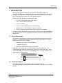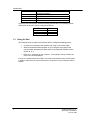
1
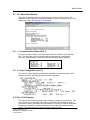
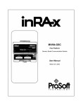
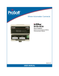
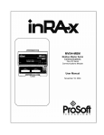
MVI94-GSC Flex Platform General Serial Communication Module Configuration/Debugger Port Users Guide June 16, 2004 ProSoft Technology, Inc. 1675 Chester Ave 4th Floor Bakersfield, CA 93301 (661) 716-5100 (661) 716-5101 Fax [email protected] Please Read This Notice Successful application of the MVI94-GSC module requires a reasonable working knowledge of the Allen-Bradley hardware and the application in which the combination is to be used. For this reason, it is important that those responsible for implementing the module satisfy themselves that the combination will meet the needs of the application without exposing personnel or equipment to unsafe or inappropriate working conditions. This manual is provided to assist the user in interfacing with the MVI94-GSC module's configuration/debug port. Every attempt has been made to assure that the information provided is accurate and a true reflection of the product's functionality. In order to assure a complete understanding of the operation of the product, the user should read all applicable Allen-Bradley documentation on the operation of the A-B hardware. Under no condition will ProSoft Technology, Inc. be responsible or liable for indirect or consequential damages resulting from the use or application of the product. Reproduction of the contents of this manual, in whole or in part, without written permission from ProSoft Technology, Inc. is prohibited. Information in this manual is subject to change without notice and does not represent a commitment on the part of ProSoft Technology, Inc. Improvements and/or changes in this manual or the product may be made at any time. These changes will be made periodically to correct technical inaccuracies or typographical errors. Additional resource documents are provided for the module. They include the following: MVI94-GSC User Manual -- This reference provides a description of the module's functionality and an introduction to its applicability to applications. This reference should be read first for an understanding of the module's operating modes and configuration requirements. Data flow diagrams are provided to display the interface between the processor, the module and the serial network. ProSoft Technology, Inc. 2000, 2001, 2002, 2003, 2004 MVI94-GSC Configuration/Debug Guide June 16, 2004 ii Table of Contents Table of Contents 1 INTRODUCTION ...............................................................................................................................................5 1.1 1.2 1.3 2 REQUIRED HARDWARE ...................................................................................................................................5 REQUIRED SOFTWARE ....................................................................................................................................5 USING THE PORT ............................................................................................................................................6 MENU OPTIONS ................................................................................................................................................7 2.1 A = DATA ANALYZER ....................................................................................................................................7 2.1.1 5=1 mSec Ticks......................................................................................................................................7 2.1.2 6=5 mSec Ticks......................................................................................................................................8 2.1.3 7=10 mSec Ticks....................................................................................................................................8 2.1.4 8=50 mSec Ticks....................................................................................................................................8 2.1.5 9=100 mSec Ticks..................................................................................................................................8 2.1.6 0=No mSec Ticks ...................................................................................................................................8 2.1.7 H=Hex Format ......................................................................................................................................8 2.1.8 A=ASCII Format ...................................................................................................................................8 2.1.9 B=Start ..................................................................................................................................................8 2.1.10 S=Stop ...................................................................................................................................................9 2.1.11 M = Main Menu.....................................................................................................................................9 2.2 B = BLOCK TRANSFER STATISTICS.................................................................................................................9 2.3 C = MODULE CONFIGURATION ......................................................................................................................9 2.4 R=RECEIVE MODULE CONFIGURATION FROM REMOTE UNIT .......................................................................10 2.5 S=SEND MODULE CONFIGURATION TO REMOTE UNIT .................................................................................10 2.6 V = VERSION INFORMATION ........................................................................................................................10 2.7 W = WARM BOOT MODULE .........................................................................................................................11 2.8 1 = COMMUNICATION STATUS (PORT 1).......................................................................................................11 2.9 6 = PORT CONFIGURATION (PORT 1) ............................................................................................................11 2.10 ESC = EXIT PROGRAM ..................................................................................................................................11 iii Introduction 1 INTRODUCTION This document contains a description and lists the functionality provided on the configuration/ debugger port of the MVI94-GSC communication module. Use of this port can help in trouble-shooting problems that may exist with the module when interfacing with an Allen-Bradley processor or the serial interface network. Facilities on the port provide the following functionality: • Full view of the module's configuration data • View of all the module's status data • Version information • Control over the module (warm boot and cold boot) • Data analyzer to view message processing on each port • Facility to upload and download the module configuration information The sections below describe the required elements, connecting to the port and using the port. Following these sections is a detailed discussion of the menu options offered when using the port. 1.1 Required Hardware The hardware requirements to interface with the configuration/debugger port are not too stringent. A personal computer with a standard serial port should suffice. For optimal performance, the minimum is required: • 80468 based processor (Pentium preferred) • 1 megabyte of memory • At least one serial communications port available Additionally, a null-modem cable is required between your PC and the port. The module's port has a DB-9 male connector at the end of a RJ-45 to DB-9 pigtail. The RJ45 end of the cable is to be placed in the MVI94-GSC Port 1 connector (top port). The cable required is displayed below: MVI94-GSC Configuration/Debug Port Cable DB-9 Male 1.2 RS-232 Host RxD 2 TxD TxD 3 RxD COM 5 COM GND Required Software The software required on your personal computer to interface with the configuration/debugger port is operating system dependent. Tested software include the following: ProSoft Technology, Inc MVI94-GSC Configuration Guide June 29, 2004 5 Introduction DOS Windows 3.1 Windows 95/98 Windows NT Linux ProComm, PS-Term and several other terminal emulation programs Terminal HyperTerminal and PS-Term HyperTerminal Minicom Any ASCII terminal emulation software package provided with your operating system should work as long as it can be configured as follows: Baud Rate Parity Data Bits Stop Bits 1.3 57,600 None 8 1 Using the Port The following steps are required to interface with the configuration/debugger port: • Connect your computer to the module's port using a null-modem cable. • Start the terminal emulation program on your computer and configure the communication parameters to those shown in the Required Software section (57600, N, 8, 1). • Enter the '?' character on your computer. If everything is set up correctly, the port's menu will be displayed. If there is no response from the module, check the communication setup and the cable. In addition, make sure you are connected to the correct port on your computer and the module. 6 ProSoft Technology, Inc. MVI94-GSC User Manual June 29, 2004 Menu Options 2 Menu Options Features available through the use of the configuration/debug port on the MVI94-GSC module are all reached using single keystrokes on your computer. There is a single main menu and several sub-menus presented on the port. To view the current selections available, press the '?' key on your computer. If you are in main menu mode, the following menu will be displayed: If this menu is not displayed, press the 'M' key to display the main menu. All facilities offered by the configuration/debugger are shown on the main menu. Each option is discussed below: 2.1 A = Data Analyzer Selection of this menu option places the program in analyzer menu mode. This mode of operation is used to display messages generated and received by the module. To view the menu options available in this mode, press the '?' key and the following menu will be displayed: This tool is extremely useful in determining the operation of the module and nodes on the network of each port. The parameters shown at the bottom of the display show the current analyzer settings. Each of the menu options is discussed in the sections below: 2.1.1 5=1 mSec Ticks This option is used to generate 1-millisecond timing marks on the display. This may help when determining communication-timing characteristics. ProSoft Technology, Inc MVI94-GSC Configuration Guide June 29, 2004 7 Menu Options 2.1.2 6=5 mSec Ticks This option is used to generate 5-millisecond timing marks on the display. This may help when determining communication-timing characteristics. 2.1.3 7=10 mSec Ticks This option is used to generate 10-millisecond timing marks on the display. This may help when determining communication-timing characteristics. 2.1.4 8=50 mSec Ticks This option is used to generate 50-millisecond timing marks on the display. This may help when determining communication-timing characteristics. 2.1.5 9=100 mSec Ticks This option is used to generate 100-millisecond timing marks on the display. This may help when determining communication-timing characteristics. 2.1.6 0=No mSec Ticks This option is used to turn the display of timing marks off. 2.1.7 H=Hex Format This option is used to select the display of the data in hexadecimal format. This format is most useful when viewing binary protocol messages. 2.1.8 A=ASCII Format This option is used to select the display of the data in ASCII format. This format is most useful when viewing ASCII protocol messages. 2.1.9 B=Start This option is used to start the data analyzer. After the key is pressed, all data transmitted and received on the currently selected port will be displayed. An example display is shown below: 8 ProSoft Technology, Inc. MVI94-GSC User Manual June 29, 2004 Menu Options Special characters used in the display are as follows: [] <> <R+> <R-> <CS> _TT_ Data enclosed in these characters represent data received on the port. Data enclosed in these characters represent data transmitted on the port. These characters are inserted when the RTS line is driven high on the port. These characters are inserted when the RTS line is dropped low on the port. These characters are displayed when the CTS line is recognized high. These characters are displayed when the timing mark interval has been reached. This parameter is user defined. 2.1.10 S=Stop This option is used to stop the analyzer. Use this option to freeze the display so the data can be analyzed. To restart the analyzer, press the 'B' key. WARNING -- When in analyzer mode, program execution will slow down. Only use this tool during a trouble-shooting session. Disable the analyzer before leaving the module to run in its normal mode. 2.1.11 M = Main Menu This menu option is used to return to the main menu mode. 2.2 B = Block Transfer Statistics This menu option is used to display the configuration and statistics of the backplane data transfer operations. After selecting this option, the following will be displayed. Selecting this option at one-second intervals can be used to determine the number of blocks transferred each second. 2.3 C = Module Configuration This option displays the general module configuration information for the MVI94-GSC module. ProSoft Technology, Inc MVI94-GSC Configuration Guide June 29, 2004 9 Menu Options 2.4 R=Receive Module Configuration from Remote Unit This option is used to send a configuration file from a remote PC to the ASCII module. After selecting the option, press the ‘Y’ key to confirm the operation. Now, transfer the file from the PC to the ASCII unit using the Ymodem file transfer protocol. When the module receives the configuration file, it will perform a warm-boot operation to load the new configuration parameters into the module. 2.5 S=Send Module Configuration to Remote Unit This option is used to send the configuration information stored in the module to a remote unit (PC). After selecting the option, press the ‘Y’ key to confirm the operation. Now, transfer the file to the remote PC using the Ymodem file transfer protocol. After the file is uploaded, it can be viewed using any text editor program. You can alter the configuration and select the receive menu option to transfer the new configuration to the module. 2.6 V = Version Information This option is used to view the current version of the software for the module and other important values. After selecting the option, the following will be displayed: This information may be requested when calling for technical support on the product. Values at the bottom of the display are important in determining module operation. The Program Scan Counter value is incremented each time a module's program cycle is complete. This value can be used to determine the frequency of program execution by pressing the 'V' key at one-second intervals. 10 ProSoft Technology, Inc. MVI94-GSC User Manual June 29, 2004 Menu Options 2.7 W = Warm Boot Module This option is selected when a warm-boot operation is required of the module. This request is usually made after configuration changes are set or to reset the module. After selecting the option, the following will be displayed: 2.8 1 = Communication Status (Port 1) This option is used to display the communication status and statistics of the specified port. This information can be informative when trouble-shooting communication problems. After selecting the option, the following information will be displayed: 2.9 6 = Port Configuration (Port 1) This option is used to display the configuration information for the selected port. After selecting the option, the following information will be displayed: 2.10 Esc = Exit Program This option is used to exit the program and to display the operating system prompt. This option should only be selected if instructed by the ProSoft Technical Support Group. If you select the option, the module will cease operation. Data will no longer be transferred between the ports and the module and between the Allen-Bradley processor and the module. This might cause an upset to a currently running process. ProSoft Technology, Inc MVI94-GSC Configuration Guide June 29, 2004 11 Menu Options 12 ProSoft Technology, Inc. MVI94-GSC User Manual June 29, 2004