1
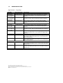
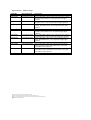
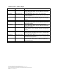
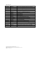
Main Line Colour Light Signal
User Manual
Document Ref. No. C64.63267 Issue 6
This Manual Is To Be Read Before Commencing The
Installation.
Wennington Road, Southport PR9 7TN. England
Tel: 01704 518000 Fax: 01704 518001
WEB SITE http://www.unipartdorman.co.uk
E MAIL address – [email protected]
Every effort has been made to ensure the accuracy of the information given in our
publications, but in accordance with our policy of continually improving our products
we reserve the right to modify designed and specifications whenever necessary. All
equipment is designed to conform to relevant British and International standards.
Every care is taken to ensure that, as far as reasonably practical, it will perform
without risk to health. It is essential that accepted codes of professional practice are
followed in the assembly, installation and commissioning of the equipment. If in
doubt with respect to any of these instructions, please consult DORMAN before
installing the device.
Dorman reserve the right to vary or modify any specification without prior notice.
DOCUMENT CONTROL
The contents of this document are copyright © Dorman 2003
Equipment and Components described in this document are protected by patent.
No part of this document may be reproduced in any form without the written permission of Dorman.
Dorman Ref. No C64.63267 Issue 6
Page 1.
Comment [D1]: This
document is the word document
used to produce the issued and
controlled .pdf of the User Manual
part number C64.63267.
The following .pdf files require
creating to make the final User
Manual, these are then joined
together in Adobe Acrobat to
create the issued and controlled
.pdf document.
1.Pages 1-28 of this document
2.Drawing Part Number
CLSH/RYGY/1P/LU
3.Page 29 of this document
4.Drawing Part Number
CLSH/3RYG/1P/LU
5.Drawing Part Number
CLSH/SRYG/1P/LU
6.Page 30 of this document
7.Railtrack Wiring Diagram SSI 4A
(supplied by Andy Denholm)
8.Railtrack Wiring Diagram SSI 3R
(supplied by Andy Denholm)
9.Railtrack Wiring Diagram RRI 4
FYY (supplied by Andy Denholm)
10.Railtrack Wiring Diagram RRI
3R (supplied by Andy Denholm)
11.Pages 31 of this document
It is the reader’s responsibility to ensure they have the correct issue of this
document. If in doubt, please contact Dorman to verify the current issue status.
AMMENDMENTS
Date.
Issue.
04/08/04
2
23/08/04
3
21/01/05
4
11/12/06
5
27/10/08
6
Alterations.
Document control page added.
Clause 4.5 Door Reversal Instructions added.
Clause 6.2.1 Rear Access cleaning instructions expanded.
Clause 6.4 Text change
Clause 2.4 Torque values added
Clause 4.2 Text added
Clause 6.2.2 Text regarding the LMT condensed
Clause 7 Text expanded
Clause 4.4 Note added detailing a cable clamp.
Clause 6.1 Note added ref lens 3 months cleaning frequency.
Clause 6.2.1 Note added ref lens cleaning and optional cleaning
agents.
Clause 2 Storage instructions inserted. All subsequent clauses
renumbered to suit.
Clause 5.4 Instruction to remove the temporary plug from the
gland entrance added.
Clause 5.1 Important Note:- ………. added.
Clause 1.4 Table of Signal variants, Module variants and spares
expanded to show additional options.
Removal of Maintenance Plans and Record Cards. Minor
alterations to associated text.
Clause 1.2 Network Rail Certificate PA05/2706 added.
Clause 1.4 Medium Range Signal and Module variants added.
Address and contact details changed to Wennington Road
The contents of this document are copyright © Dorman 2003
Equipment and Components described in this document are protected by patent.
No part of this document may be reproduced in any form without the written permission of Dorman.
Dorman Ref. No C64.63267 Issue 6
Page 2.
DCC
No.
2452
Initials.
2532
DR
2669
DR
3093
DR
4360
AD
DR
TABLE OF CONTENTS
DOCUMENT CONTROL ...........................................................................................................................................1
TABLE OF CONTENTS...............................................................................................................................................3
1
INTRODUCTION ................................................................................................................................................4
1.1
COMPLIANCES ................................................................................................................................................5
1.2
APPROVALS ......................................................................................................................................................5
1.3
KEY SPECIFICATIONS ...................................................................................................................................5
1.4
ORDERING DETAIL .......................................................................................................................................6
2
STORAGE .............................................................................................................................................................11
3
SIGNAL ASSEMBLY AND ELECTRICAL CONNECTION.....................................................................12
3.1
Safety Requirements..................................................................................................................................12
3.2
Tooling ..........................................................................................................................................................12
3.3
Recommended Sundry Items ..................................................................................................................12
3.4
Housing Assembly and Mechanical Adjustment .................................................................................13
3.5
Colour Light Signal Module Assembly and mechanical adjustment...............................................14
3.6
Electrical Connections ..............................................................................................................................14
3.7
Three Aspect Signal ...................................................................................................................................14
4
DESIGN..................................................................................................................................................................15
4.1
Mechanical....................................................................................................................................................15
4.2
Signal sighting...............................................................................................................................................15
4.3
Maintenance.................................................................................................................................................15
4.4
Electrical .......................................................................................................................................................16
4.4.1
General.....................................................................................................................................................16
4.4.2
Lamp Proving and Power Supplies ....................................................................................................16
4.4.3
Flashing Aspects .....................................................................................................................................16
4.4.4
Circuits .....................................................................................................................................................16
5
INSTALLATION..................................................................................................................................................17
5.1
Mechanical....................................................................................................................................................17
5.2
Signal Alignment..........................................................................................................................................18
5.3
Earth Continuity Bonding.........................................................................................................................18
5.4
Electrical Connections ..............................................................................................................................18
5.5
Door Reversal Instructions .....................................................................................................................19
6
NEW WORKS TESTING .................................................................................................................................22
7
MAINTENANCE .................................................................................................................................................23
7.1
Preventative Activities...............................................................................................................................23
7.2
Notes on Access and cleaning activities...............................................................................................23
7.2.1
Rear Access.............................................................................................................................................23
7.2.2
Light Measurement................................................................................................................................25
7.3
Maintenance Changing and Testing Activities .....................................................................................26
7.4
Fault Finding.................................................................................................................................................26
8
RECOVERY AND RESERVICING ..................................................................................................................27
APPENDIX D1 ..............................................................................................................................................................28
Two Aperture General Arrangement.................................................................................................................28
APPENDIX D2 ..............................................................................................................................................................29
Single Aperture General Arrangements.............................................................................................................29
APPENDIX D3 ..............................................................................................................................................................30
Typical Wiring...........................................................................................................................................................30
APPENDIX M1..............................................................................................................................................................31
Suggested SMTH Test Plan....................................................................................................................................31
The contents of this document are copyright © Dorman 2003
Equipment and Components described in this document are protected by patent.
No part of this document may be reproduced in any form without the written permission of Dorman.
Dorman Ref. No C64.63267 Issue 6
Page 3.
1
INTRODUCTION
The Dorman Colour Light Signal System offers the user a versatile yet simple
signalling product for installation in a wide variety of applications. The signal as
supplied for use on Infrastructure owned by Network Rail will interface to all
standard types of route relay, geographical and solid state interlocking systems as
used on the main line railways in the UK. It is quickly fitted to the standard
mechanical mounting arrangements that are available from all suppliers of signal
posts, gantries and cantilever structures.
The modular system offers maximum flexibility in the provision of a cost effective
solution to the varied requirements of major new works, renewals and maintenance
installations.
The key to the simplicity of the system is the minimum number of user defined
elements. These are:
•
Support Housing
This facilitates the Colour Light Signal Modules to be mounted on the signalling
structure and aligned to the correct sighting point of the signal.
•
Colour Light Signal Module
The desired aspect arrangement of the signal is determined by the appropriate
choice of Colour Light Signal Modules. (CLSM)
•
Backboard and Hoods
The Backboard gives the signal aspects a uniform black border of 300mm from
the centre of aperture.
Hoods in lengths of 300mm are standard. Other lengths are available by special
request.
In addition maintenance of the signal is enhanced by the following features
•
Anti scratch lens coating
•
Improved access
•
True light output measurements
The contents of this document are copyright © Dorman 2003
Equipment and Components described in this document are protected by patent.
No part of this document may be reproduced in any form without the written permission of Dorman.
Dorman Ref. No C64.63267 Issue 6
Page 4.
1.1
COMPLIANCES
Railway Group Standards
Network Rail
GK/RT0031, GK/RT0037
RT/E/S 10062
89/336/EEC
CE Certification
1.2
APPROVALS
Unrestricted Network Rail Certificate Nos.
Colour Light Signal Module
Colour Light Signal Module (Medium range)
Housing
1.3
PA05/01515
PA05/02706
PA05/01873
KEY SPECIFICATIONS
Operating Temperature Range
-25OC to +40OC
Operating Voltage AC
Operating Voltage DC
Max 121V
Max 145V
Nominal Operating Current
300 mA @ 110Vac
330 mA @ 120Vdc
Min 88V
Min 88V
Current Proving
Relay Based Interlocking
Solid State Interlocking (SSI)
BR941A
Return Current Path 1 or 4
Light Output Intensity (all colours)
RT/E/S/10062
Light Output Colour
Red
Yellow
Green
BS1376 Class C (Restricted)
BS1376 Class B
BS1376 Class C
Aspect Configurations
1, 2, 3 or 4
Flashing Aspects
All aspects are capable of being
flashed under control of the
interlocking.
Weight
4 Aspect Signal (signal with 2 modules)
3 Aspect Signal (signal with 1 module)
3 Aspect Short Signal (signal with 1 module)
The contents of this document are copyright © Dorman 2003
Equipment and Components described in this document are protected by patent.
No part of this document may be reproduced in any form without the written permission of Dorman.
Dorman Ref. No C64.63267 Issue 6
Page 5.
43kg
33kg
26kg
1.4
ORDERING DETAIL
Signal Variants – Long Range
PADS No
Dorman Part No
Description
0086/009158
former NRS No
0050/001274
0086/009152
former NRS No
0050/001272
0086/009155
CLSH/RYGY/1P/LU
Dorman LED Long Range Colour Light Signal Head, 4 Aspect,
Red Yellow Green Yellow, 110V, Lamp Proved, Left Upper
Quadrant
Dorman LED Long Range Colour Light Signal Head, 3 Aspect,
Red Yellow Green, 110V, Lamp Proved, Left Upper Quadrant
CLSH/SRYG/1P/LU
Dorman LED Long Range Short Colour Light Signal Head,
3 Aspect, Red Yellow Green, 110V, Lamp Proved, Left Upper
Quadrant
0086/009159
Former NRS No
0050/001284
0086/009153
Former NRS No
0050/001282
0086/009156
CLSH/RYGY/1P/RU
Dorman LED Long Range Colour Light Signal Head, 4 Aspect,
Red Yellow Green Yellow, 110V, Lamp Proved, Right Upper
Quadrant
Dorman LED Long Range Colour Light Signal Head, 3 Aspect,
Red Yellow Green, 110V, Lamp Proved, Right Upper Quadrant
CLSH/SRYG/1P/RU
Dorman LED Long Range Short Colour Light Signal Head,
3 Aspect, Red Yellow Green, 110V, Lamp Proved, Right Upper
Quadrant
0086/009154
CLGH/3RYG/1P/BH
0086/009160
CLGH/RYGY/1P/BH
Dorman LED Long Range Short Ground Mounting Colour Light
Signal Head, 3 Aspect, Red Yellow Green, 110V, Lamp Proved,
Bottom Half Quadrant.
Dorman LED Long Range Ground Mounting Colour Light Signal
Head, 4 Aspect, Red Yellow Green Yellow, 110V, Lamp Proved,
Bottom Half Quadrant.
0086/009165
CLTH/3RYG/1P/BH
0086/009167
CLTH/RYGY/1P/BH
CLSH/3RYG/1P/LU
CLSH/3RYG/1P/RU
Dorman LED Long Range Short Colour Light Tunnel Signal
Head, 3 Aspect, Red Yellow Green, 110V, Lamp Proved, Bottom
Half Quadrant.
Dorman LED Long Range Colour Light Tunnel Signal Head,
4 Aspect, Red Yellow green Yellow, 110V, Lamp Proved, Bottom
Half Quadrant.
The contents of this document are copyright © Dorman 2003
Equipment and Components described in this document are protected by patent.
No part of this document may be reproduced in any form without the written permission of Dorman.
Dorman Ref. No C64.63267 Issue 6
Page 6.
Signal Variants – Medium Range
PADS No
Dorman Part No
Description
0086/009040
CLMH/RYGY/1P/LU
0086/009041
CLMH/3RYG/1P/LU
0086/009042
CLMH/SRYG/1P/LU
Dorman LED Medium Range Colour Light Signal Head, 4 Aspect,
Red Yellow Green Yellow, 110V, Lamp Proved, Left Upper
Quadrant
Dorman LED Medium Range Colour Light Signal Head, 3 Aspect,
Red Yellow Green, 110V, Lamp Proved, Left Upper Quadrant
Dorman LED Medium Range Short Colour Light Signal Head,
3 Aspect, Red Yellow Green, 110V, Lamp Proved, Left Upper
Quadrant
0086/009043
CLMH/RYGY/1P/RU
0086/009044
CLMH/3RYG/1P/RU
0086/009045
CLMH/SRYG/1P/RU
0086/009046
CLMH/3RYG/1P/BH
0086/009047
CLMH/RYGY/1P/BH
Dorman LED Medium Range Colour Light Signal Head, 4 Aspect,
Red Yellow Green Yellow, 110V, Lamp Proved, Right Upper
Quadrant
Dorman LED Medium Range Colour Light Signal Head, 3 Aspect,
Red Yellow Green, 110V, Lamp Proved, Right Upper Quadrant
Dorman LED Medium Range Short Colour Light Signal Head, 3
Aspect, Red Yellow Green, 110V, Lamp Proved, Right Upper
Quadrant
Dorman LED Medium Range Short Ground Mounting Colour
Light Signal Head, 3 Aspect, Red Yellow Green, 110V, Lamp
Proved, Bottom Half Quadrant.
Dorman LED Medium Range Ground Mounting Colour Light
Signal Head, 4 Aspect, Red Yellow Green Yellow, 110V, Lamp
Proved, Bottom Half Quadrant.
The contents of this document are copyright © Dorman 2003
Equipment and Components described in this document are protected by patent.
No part of this document may be reproduced in any form without the written permission of Dorman.
Dorman Ref. No C64.63267 Issue 6
Page 7.
Module Variants – Long Range
PADS No
Dorman Part No.
Description
0086/009200
CLSM/3RYG/1P/LU
0086/009201
CLSM/4RYG/1P/LU
0086/009202
CLSM/4Y--/1P/LU
Dorman LED Long Range Colour Light Signal Module, 3 Aspect,
Red Yellow Green, 110V ac / 120V dc, Lamp Proved, Left Upper
Quadrant
Dorman LED Long Range Colour Light Signal Module, 4 Aspect,
Red Yellow Green, 110V ac / 120V dc, Lamp Proved, Left Upper
Quadrant
Dorman LED Long Range Colour Light Signal Module, 4 Aspect,
Yellow, 110V ac / 120V dc, Lamp Proved, Left Upper Quadrant
0086/009203
CLSM/3RYG/1P/RU
0086/009204
CLSM/4RYG/1P/RU
0086/009205
CLSM/4Y--/1P/RU
0086/009206
CLTM/3RYG/1P/BH
0086/009207
CLTM/4RYG/1P/BH
0086/009208
CLTM/4Y--/1P/BH
Dorman LED Long Range Colour Light Signal Module, 3 Aspect,
Red Yellow Green, 110V ac / 120V dc, Lamp Proved, Right
Upper Quadrant
Dorman LED Long Range Colour Light Signal Module, 4 Aspect,
Red Yellow Green, 110V ac / 120V dc, Lamp Proved, Right
Upper Quadrant
Dorman LED Long Range Colour Light Signal Module, 4 Aspect,
Yellow, 110V ac / 120V dc, Lamp Proved, Right Upper Quadrant
Dorman LED Long Range Colour Light Ground/Tunnel Signal
Module, 3 Aspect, Red Yellow Green, 110V ac / 120V dc, Lamp
Proved, Bottom Half Quadrant
Dorman LED Long Range Colour Light Ground/Tunnel Signal
Module, 4 Aspect, Red Yellow Green, 110V ac / 120V dc, Lamp
Proved, Bottom Half Quadrant.
Dorman LED Long Range Colour Light Ground/Tunnel Signal
Module, 4 Aspect, Yellow, 110V ac / 120V dc, Lamp Proved,
Bottom Half Quadrant.
The contents of this document are copyright © Dorman 2003
Equipment and Components described in this document are protected by patent.
No part of this document may be reproduced in any form without the written permission of Dorman.
Dorman Ref. No C64.63267 Issue 6
Page 8.
Module Variants – Medium Range
PADS No
Dorman Part No.
Description
0086/009170
CLMM/3RYG/1P/LU
0086/009171
CLMM/4RYG/1P/LU
0086/009172
CLMM/4Y--/1P/LU
Dorman LED Medium Range Colour Light Signal Module,
3 Aspect, Red Yellow Green, 110V ac / 120V dc, Lamp Proved,
Left Upper Quadrant
Dorman LED Medium Range Colour Light Signal Module,
4 Aspect, Red Yellow Green, 110V ac / 120V dc, Lamp Proved,
Left Upper Quadrant
Dorman LED Medium Range Colour Light Signal Module,
4 Aspect, Yellow, 110V ac / 120V dc, Lamp Proved, Left Upper
Quadrant
0086/009173
CLMM/3RYG/1P/RU
0086/009174
CLMM/4RYG/1P/RU
0086/009175
CLMM/4Y--/1P/RU
0086/009178
CLMM/3RYG/1P/BH
0086/009176
CLMM/4RYG/1P/BH
0086/009177
CLMM/4Y--/1P/BH
Dorman LED Medium Range Colour Light Signal Module,
3 Aspect, Red Yellow Green, 110V ac / 120V dc, Lamp Proved,
Right Upper Quadrant
Dorman LED Medium Range Colour Light Signal Module,
4 Aspect, Red Yellow Green, 110V ac / 120V dc, Lamp Proved,
Right Upper Quadrant
Dorman LED Medium Range Colour Light Signal Module,
4 Aspect, Yellow, 110V ac / 120V dc, Lamp Proved, Right Upper
Quadrant
Dorman LED Medium Range Colour Light Ground/Tunnel Signal
Module, 3 Aspect, Red Yellow Green, 110V ac / 120V dc, Lamp
Proved, Bottom Half Quadrant
Dorman LED Medium Range Colour Light Ground/Tunnel Signal
Module, 4 Aspect, Red Yellow Green, 110V ac / 120V dc, Lamp
Proved, Bottom Half Quadrant.
Dorman LED Medium Range Colour Light Ground/Tunnel Signal
Module, 4 Aspect, Yellow, 110V ac / 120V dc, Lamp Proved,
Bottom Half Quadrant.
The contents of this document are copyright © Dorman 2003
Equipment and Components described in this document are protected by patent.
No part of this document may be reproduced in any form without the written permission of Dorman.
Dorman Ref. No C64.63267 Issue 6
Page 9.
Spare Parts List
PADS No
0086/009220
0086/009221
0086/009222
0086/009223
0050/001346
0086/009923
0086/009001
0086/009002
0086/009003
0086/009004
0086/009005
0086/009006
0086/009007
Dorman Part No.
D86.85004
D86.85003
D86.85010
D86.85018
B86.85019
B20.19104
B86.85014
B86.85024
B20.19108
B86.85007
B20.19156
B20.19123
B86.85023
D86.85052
LMT 02
LMT 02 RECAL
B16.15281
C64.63267
D86.85087
D86.85056
B20.19183
D86.85057
D86.85058
D86.85059
D86.85060
Description
4 Aspect Colour Light Signal 2 Aperture Frame Assembly
3 Aspect Colour Light Signal 1 Aperture Frame Assembly
3 Aspect Short Colour Light Signal 1 Aperture Frame Assembly
4 Aspect Colour Light Tunnel Signal 2 Aperture Frame Assembly
75mm long Colour Light Signal Visor
300mm long Colour Light Signal Visor
550mm long Colour Light Signal Visor
550mm long ¾ round Colour Light Signal Visor
4 Aspect Backboard
3 Aspect Backboard
Short 3 Aspect Backboard
Backboard Extension
Lens Blanking Cover
Colour Light Signal Replacement Cover Kit
Colour Light Signal Measuring Tool
Colour Light Signal Measuring Tool Recalibration
Colour Light Signal CD ROM
Colour Light Signal Manual
CLS 40mm Offset Mounting Plate Assembly – for A Frame
CLS 40mm Offset Mounting Plate Assembly
CLS Lower Backboard Extension, 25mm Joggle
CLS Full Upper Backboard Extension, 25mm Joggle
CLS (Pos 3JI) Upper Backboard Extension, 25mm Joggle
CLS (Pos 6JI) Upper Backboard Extension, 25mm Joggle
CLS (Pos 3+6) Upper Backboard Extension, 25mm Joggle
The contents of this document are copyright © Dorman 2003
Equipment and Components described in this document are protected by patent.
No part of this document may be reproduced in any form without the written permission of Dorman.
Dorman Ref. No C64.63267 Issue 6
Page 10.
2
STORAGE
The signal modules are designed to ‘breathe’ through a vent situated on the bottom
face of the module. This vent must be kept clear of any accumulation of standing
water; failure to do this will result in water ingress into the module.
Complete signals are supplied on pallets fixed in an UPRIGHT position. This is the
intended operating condition of the signals, and the breathing mechanism only
operates correctly in this orientation.
DO NOT store the signals or individual modules outside in any other orientation
other than UPRIGHT.
The contents of this document are copyright © Dorman 2003
Equipment and Components described in this document are protected by patent.
No part of this document may be reproduced in any form without the written permission of Dorman.
Dorman Ref. No C64.63267 Issue 6
Page 11.
3
SIGNAL ASSEMBLY AND ELECTRICAL CONNECTION
The numbers in parentheses in the following description refer to the part numbers
as shown on drawing number CLSH/RYGY/1P/LU which is shown in Appendix D1 of
this document.
3.1
Safety Requirements
In general before commencing assembly, any local safety requirements affecting the
continued safe working environment of the signalling installation, either directly or
indirectly should be carried out.
In particular concerning the signal, when assembly is complete, the users should note
that the signal weighs 43kg. The weight of the signal may be significantly reduced to
23kg by disconnecting and removing the Colour Light Signal Modules (1, 2) prior to
lift.
It is the user’s responsibility to ensure that, if the signal is to be lifted then suitable
certificated lifting apparatus and/or other precautions are employed.
The signal should only be assembled both mechanically and electrically, by staff
deemed competent in these fields by their employer.
It is the user’s responsibility to ensure that the signal is installed and/or maintained
by certificated and competent staff.
There are no specific competencies required for the signal.
Independent national competence accreditation schemes are in use in the UK.
For further details of such a scheme, the information is available from the
Institute of Railway Signalling Engineers.
3.2
Tooling
Tools used in the assembly of the signal (except for lifting etc) need only be limited
to hand operated types. A typical tooling requirement required would be:
Socket set comprising lever and 2BA, 7mmAF, 8mmAF, 10mmAF 17mmAF, and
30mmAF sockets.
Open ended spanners 30mmAF, 17mmAF (for signal alignment)
Calibrated Torque wrench with a maximum of 40 Nm setting.
Calibrated Crimping tool (PIDG compatible)
Allen Keys 2.5mmAF, 3mmAF and 4mmAF (for removal of visors, backboard and
changing hinge opening side)
Pozi drive screw driver
Wire Cutters, Wire strippers, Padlock Key for RKB221 lock
Light Measuring Tool (Part no’s to be advised)
3.3
Recommended Sundry Items
It is recommended that a supply of 2BA nuts, plain washers, sliding links and 2BA
PIDG Ring Crimps are available to the installation staff.
The contents of this document are copyright © Dorman 2003
Equipment and Components described in this document are protected by patent.
No part of this document may be reproduced in any form without the written permission of Dorman.
Dorman Ref. No C64.63267 Issue 6
Page 12.
3.4
Housing Assembly and Mechanical Adjustment
The complete four aspect signal is comprised of two cast Colour Light Signal
Modules (CLSM) (1, 2), door (3), two-aperture frame (5), two-aperture backboard
(6), backboard extension (8), mounting plate (9), and two visors (7).
The two-aperture frame (5) and the mounting plate (9) are always factory assembled
together. The other listed parts may require mounting onto the aluminium
fabrication (5) and adjustment as required for signal sighting purposes etc.
Lifting of the complete signal into position onto the support structure is achieved by
use of the two M16 lifting eyes located near to the top on either side of the
aluminium frame (5). These may be removed after installation of the signal.
Fixing of the signal to the support structure is by the use of four M20 bolts through
the Mounting Plate (9) into locking or prevailing torque nuts underneath the
platform (not shown).
Note the M20 nuts, washers and bolts are customer provided to match supporting
structure requirements.
In order to sight the signal at the correct distance from the signal, the two aperture
frame (5) is capable of forward and backward tilt adjustment about the pivot shaft
It is fixed into position by
that is located on the mounting plate (9) by +4O.
tightening to a torque setting of 40 Nm, the Vertical Tilt Adjustment Clamp Bolts
located on both sides of the mounting plate (9).
Rotational adjustment of the signal by +6O is facilitated by the 22mm slotted
mounting holes machined into the mounting plate (9). This allows signal sighting to
be set at the correct angle relative to the track.
To allow the correct sighting point to be used to align the signal, a Sighting Scope is
affixed to the aluminium enclosure (1). This will allow the user to see the sighting
point via a magnified image. A circular etched ring on the sighting scope will allow
the user to align the signal accurately.
The door (3) is mounted on hinges either at the rear left or the rear right of the
aluminium fabrication (5). The door is normally factory set to open to the left, but
the hinges and the stay may be moved to allow the door to open to the right by the
user if desired.
The hinges are fixed to the aluminium frame (5) by two M5 socket headed machine
screws and nuts. The door is held to rear of the two-aperture frame (5), by the use
of a handle fitted bolt, that may be secured by an RKB221 Padlock, which is to be
supplied by the customer.
The backboard (6) is secured to the front of the two-aperture frame (5) by the use
of six M5 socket headed countersunk screws. The backboard extension (8) is affixed
to the backboard (6) by the use of a further four M5 socket headed countersunk
screws into captive nuts. (Torque: 1.5 Nm)
The contents of this document are copyright © Dorman 2003
Equipment and Components described in this document are protected by patent.
No part of this document may be reproduced in any form without the written permission of Dorman.
Dorman Ref. No C64.63267 Issue 6
Page 13.
The visors (7) are affixed to the two-aperture frame (5) by the use of four M5
socket headed countersunk screws. (Torque: 1.5 Nm)
3.5
Colour Light Signal Module Assembly and mechanical adjustment
The Colour Light Signal Module (1) is located into the two-aperture frame (5) by use
of the pivot shaft at the bottom of the mounting plate (9). It is held in place by use
of a spring loaded latch assembly at it’s top, which clips over a similar mounting shaft
and is secured by a RKB221 Padlock which is supplied by the customer.
The Colour Light Signal Module (2) is similarly mounted and secured onto the twoaperture frame (5) by use of shafts, latch and RKB221 Padlock.
3.6
Electrical Connections
Electrical inter-connection of the Colour Light Signal Modules (1 and 2) is
completed by connecting the plug from (2) into the socket mounted on (1).
Access to the terminals to allow wiring of the signal to the signalling circuitry is
effected by removal of the four captive M5 Pozi countersunk screws on Colour Light
Signal Module (1) only. This will allow the lid of the terminal box to be removed.
There is no user access at the rear of Colour Light Signal Module (2), which is similar
in appearance to Colour Light Signal Module (1).
Within the terminal box, 2BA stud blocks are provided. PIDG ring crimps on each
conductor locked down by 2BA nuts should be used in order to connect the tail
cable to the stud block.
Temporary disconnection of each circuit may be achieved by use of sliding 2BA links.
A typical wiring diagram is provided in Appendix W1 of this document.
Please note the signal is supplied with wire links between terminals 2,4, 6 and 8. The
relevant wire links should be removed when the signal is connected to SSI.
Full signalling wiring diagrams will be provided by the design office responsible for
the installation.
When wiring is completed the lid of the terminal box is re-fixed using the four M5
Pozi countersunk screws.
Prior to bringing the signal into use, an overall black bag with a superimposed white
cross may be secured temporarily around the back of the signal door.
3.7
Three Aspect Signal
A three aspect signal is similar in construction, assembly and connection, but has a
one-aperture backboard and only 1 visor.
Drawing number CLSH/3RYG/1P/LU for this version is given in Appendix D2
The contents of this document are copyright © Dorman 2003
Equipment and Components described in this document are protected by patent.
No part of this document may be reproduced in any form without the written permission of Dorman.
Dorman Ref. No C64.63267 Issue 6
Page 14.
4
DESIGN
The signal has been designed to ensure that the design, installation, commissioning
and maintenance any new signalling scheme or retrofit renewal is as effective as
possible. There are minimal differences in its use, compared with traditional forms
of signal that are easily encompassed by existing standards and specifications.
4.1
Mechanical
The signal has been designed to fit the standard mounting arrangements using M20
bolts and are shown for reference on the drawing given in Appendix D1
If in addition to the main signal head, the signal installation requires a Position Light
Junction Indicator, Position Light Signal, or any alphanumeric indicator then the
standard support frames as shown in the BRS SE series of drawings or other
approved methods are to be used. Designers are reminded that the two-aperture
frame is not designed to support any other signalling equipment.
4.2
Signal sighting
Information regarding the physical dimensions of the signal in order to assist the
design staff preparing standard sighting forms to GK/RT 0037 are given on Diagram
CLSH/RYGY/1P/LU.
It should be noted that as there is no “hot strip” present on the signal lenses, the
signal will be ordered as a handed item. A left handed signal is one which is mounted
to the left of the centreline of the track and conversely a right handed signal is one
that is one to the right of the centreline of the track. Left hand and right handed
CLSMs are mounted on the same aluminium frame but user configuration of the
CLSM is not possible.
Design staff and staff competent to sight signals should be aware are that there are
no special provisions regarding the use of the signal.
4.3
Maintenance
One of the key maintenance features of the signal is that of its ability to be cleaned
from the rear. It is therefore of particular interest to design staff and staff
competent to sight signals, that the use of larger sighting boards other than the
standard 1100mm x 600mm (supplied with the signal) may be used in order to
further improve conspicuity against light cluttered backgrounds. E.g. Urban areas.
The contents of this document are copyright © Dorman 2003
Equipment and Components described in this document are protected by patent.
No part of this document may be reproduced in any form without the written permission of Dorman.
Dorman Ref. No C64.63267 Issue 6
Page 15.
4.4
Electrical
4.4.1 General
The signal will interface with existing relay based or Solid State Interlocking (SSI) that
is in use within the UK. It should be noted that due to the high reliability of the
signal, no filament checking relay (EKR) is provided, although terminals 9-12 are
provided for the termination of the appropriate cable cores in retro-fit applications.
The signal is supplied complete with all removable components provided with earth
bonding straps. No special design is required in this respect.
4.4.2 Lamp Proving and Power Supplies
The signal is designed to interface to a standard lamp proving relay to specification
BR941A, or Current Proving Paths 1 or 4 for SSI. It is recommended that these
standard components are used in conjunction with the signal for new installations.
For use of the signal with other current proving arrangements then advice should be
sought from Dorman.
The nominal operating voltage is 110Vac, with a typical power consumption of 30W
per aspect. The signal will maintain its light output between voltage variations as
defined in RT/E/S 10062. (Typically 88V-121Vac.)
For further information for use on poorly regulated power supplies then advice
should be sought from Dorman.
4.4.3 Flashing Aspects
There are no special requirements in order to provide flashing aspects on relay
based interlockings. When using the signal on Solid State Interlocking Trackside
Functional Modules (TFMs), the ballast resistor that otherwise has to be provided for
conventional signal heads to maintain energisation of the Lamp Proving Relay (ECR)
during the dim phase of the flash should be removed. However due to the design of
the SSI system itself, it is not possible to use the resulting free outputs.
4.4.4 Circuits
Typical circuits that may be employed are given in Appendix D3
The contents of this document are copyright © Dorman 2003
Equipment and Components described in this document are protected by patent.
No part of this document may be reproduced in any form without the written permission of Dorman.
Dorman Ref. No C64.63267 Issue 6
Page 16.
5
INSTALLATION
When installing the signal on Network Rail, the installation standards of the signal
should follow the general provisions of the Signalling Installation Handbook.
This publication is available from Network Rail.
In general terms, the installation of the signal will take place during engineering
possessions of the working railway, and structures used to support the signal and
other items of equipment will be designed in accordance with prevailing legislation
and standards and are outside the scope of this information booklet.
5.1
Mechanical
The order of installation is not predefined by the design of the signal. It may be lifted
as a complete mechanical unit or may be taken in its constituent parts to a signal
gantry or cantilever and then assembled as described above.
When installing the signal, remove the backboard extension and refit the fixing
screws to the main backboard (to blank off the fixing holes). If required, fit the
backboard extension to the bottom of the main backboard using the 4 screws
already in place.
However care should be taken with the backboard extension piece to avoid it being
damaged if lifting a completely dressed signal, as this component protrudes below the
lower edge of the two-aperture frame.
Important Note:- All warning labels must be removed from the front face of the
signal during installation.
The signal is affixed to the support structure by means of 4 x M20 bolts washers and
nuts as defined by the design engineer and provided by the customer. In order to
install these bolts it is recommended to remove the lower CLSM. Once installed,
initial tightening of these bolts should be sufficient to secure the signal to the
structure.
When removing the CLSMs from the frame, do not place the units facing downwards
onto any surface that could scratch the outer lens. Never leave the units with the
lens facing the mid day sun as the lens is capable of concentrating the light energy
enough to damage the LEDs with the build up of heat, cover the units.
Mounting of the CLSMs to the frame is as follows.
The lower front edge of the CLSM is placed over the pivot shaft and the CLSM is
then rotated forwards over the shaft and secured by the spring loaded latch on its
top engaging onto a similar shaft in one movement. A padlock is then used to
prevent unauthorised access.
Visors are fitted to the backboard.
Prior to bring the signal into use, an overall black bag with a superimposed front
facing white cross may be secured temporarily around the signal.
The contents of this document are copyright © Dorman 2003
Equipment and Components described in this document are protected by patent.
No part of this document may be reproduced in any form without the written permission of Dorman.
Dorman Ref. No C64.63267 Issue 6
Page 17.
5.2
Signal Alignment
The signal is supplied complete with a signal alignment scope that is fixed on the top
of the lower Colour Light Signal Module. This module will have to be mounted on
to the support frame in order to align the signal.
When looking through the scope the user will note that the observed view is
magnified. (Ensure front and rear scope lenses are clean)
Etched onto the lens of the scope is circle that is calibrated for 3O. When using the
scope, adjustment of the M20 bolts and tilting of the two-aperture frame about the
pivot shaft will allow accurate alignment of the signal to be set. When the desired
alignment setting is reached, final tightening of the M20 bolts and the vertical tilt
adjustment clamp bolts can be undertaken.
These latter bolts should be tightened to 40Nm.
Note: The torque setting for the M20 bolts should be given by the design engineer.
5.3
Earth Continuity Bonding
The Colour Light Signal Modules and rear door once mounted and secured should
be bonded to the frame by use of the earth bonding straps. These are fitted to the
components and the frame by M5 hex headed screws. They should be tightened to a
torque setting of 1.5Nm
The front backboard, backboard extension piece, and visors are deemed to be
bonded by virtue of their correctly installed permanent fixings.
Bonding of the signal to the structure is deemed to be effective by the M20 fixing
bolts.
If the customer requires additional bonding points they are available on the bottom
of the aluminium frame.
5.4
Electrical Connections
Electrical inter-connection of the two CLSM is completed by connecting the plug
from the upper CLSM into the socket mounted on the lower CLSM
Access to the terminals to allow wiring of the signal to the signalling circuitry is
effected by removal of the four captive M5 Pozi countersunk screws in the rear
cover on the lower CLSM only. This will allow the lid of the terminal box to be
removed. There is no user access at the rear of the upper CLSM, which is similar in
appearance to lower CLSM.
Within the terminal box, standard 2BA stud blocks are provided. Each link is
labelled 1 to 12 from left to right as seen from the rear. PIDG ring crimps on each
conductor locked down by 2BA nuts should be used in order to connect the tail
cable to the stud block.
Temporary disconnection of each circuit may be achieved by use of sliding 2BA links.
The contents of this document are copyright © Dorman 2003
Equipment and Components described in this document are protected by patent.
No part of this document may be reproduced in any form without the written permission of Dorman.
Dorman Ref. No C64.63267 Issue 6
Page 18.
The tail cable to the signal is routed to the terminal blocks through a gland at the
bottom of the lower CLSM. It will be necessary to remove the temporary sealing
plug from the gland entrance to allow cable entry. When tightened this gland will
support the cable and complete the sealing of the enclosure without need for further
accessories.
However a clamp is provided to be fitted around the feed cable which will prevent
the cable from falling back through the cable entry hole at the base of the signal
housing if/when a module is removed.
Full signalling wiring diagrams will be provided by the design office responsible for
the installation.
When wiring is completed the lid of the terminal box is re-fixed using the four M5
Pozi countersunk screws.
5.5
Door Reversal Instructions
Note the assembly order of any fasteners removed in the instructions below, to ensure
correct re-assembly sequence.
The illustration entitled “View On Rear Of Signal Frame Assembly”
shows the positions of the components referred to in the following
paragraphs.
Undo the two dome nuts (a) securing the door stay bracket to the door. Undo the
two button head screws (b) securing the frame stay bracket to the frame. Remove
the stay assembly (c) as one complete unit. Do not dismantle the stay assembly into
its component parts.
Lift the door off its hinges.
Door Alterations.
1. Remove the 4-off rubber doorstops (d).
2. Remove the 2-off door hinges (e). Drive out the hinge pins and replace in the
opposite end of the door hinges.
Drive out hinge pin.
The contents of this document are copyright © Dorman 2003
Equipment and Components described in this document are protected by patent.
No part of this document may be reproduced in any form without the written permission of Dorman.
Dorman Ref. No C64.63267 Issue 6
Page 19.
Replace pin in
opposite end.
3. Replace the hinges on the opposite side of the door. Do not tighten at this stage
to allow later door / frame alignment.
4. Replace the rubber door stops on the opposite clinch studs.
5. Remove the 2-off earth straps (f) from the base of the door and replace on the
opposite side of the door.
Frame Alterations.
1. Remove the frame earth strap (g) and replace on the opposite side of the frame.
2. Remove the 2-off frame hinges (h). Drive out the end caps and replace in the
opposite end of the frame hinges.
3. Replace the hinges on the opposite side of the frame. Do not tighten at this stage
to allow later door / frame alignment.
Remount the door onto the frame. Adjust the hinges for satisfactory door operation.
Note – Set the door to give 1mm clearance between the inner face of the door and
the top of the rolled edge on the frame. Tighten all hinge fasteners.
Turn the stay over and refit to opposite side.
Stay position on RH hinged door.
The contents of this document are copyright © Dorman 2003
Equipment and Components described in this document are protected by patent.
No part of this document may be reproduced in any form without the written permission of Dorman.
Dorman Ref. No C64.63267 Issue 6
Page 20.
View On Rear Of Signal Frame Assembly
d
e
h
a
b
c
f
The contents of this document are copyright © Dorman 2003
Equipment and Components described in this document are protected by patent.
No part of this document may be reproduced in any form without the written permission of Dorman.
Dorman Ref. No C64.63267 Issue 6
Page 21.
g
6
NEW WORKS TESTING
New Works Testing of the signal is undertaken using the standards laid down by the
customer. Typically on Network Rail infrastructure this will be to the provisions of
the Signal Testing Handbook. Copies of this document are available from Network
Rail.
It is the responsibility of the Testing Engineer to provide all necessary documentation
pertaining to the testing of the signal. There are a number of features of the
Dorman signal which require testing in a different manner to that of a filament lamp
signal. These should be taken into account when preparing any specification for new
works testing.
Parameter
Signal Alignment.
Signal Head Voltage.
Light Output
Hot Strips
Correct CLSMs
Wire Count.
Filament Proving
Difference to filament signal
Alignment scope is used.
In terminal box on links.
Over CLSM lens by use of Light Measuring
Tool (LMT). Acceptable light output is >60%
of the original manufacturers setting as
indicated on the rear of the CLSM.
No hot strips are provided. The correct
handed signal should be installed.
Correct modules are installed to give aspect
arrangement on signal sighting form
Only user terminal wiring may be checked. A
Certificate of Conformity is provided in each
signal head.
No filament proving is provided.
The contents of this document are copyright © Dorman 2003
Equipment and Components described in this document are protected by patent.
No part of this document may be reproduced in any form without the written permission of Dorman.
Dorman Ref. No C64.63267 Issue 6
Page 22.
7
MAINTENANCE
7.1
Preventative Activities
The signal has been designed to reduce maintenance activities to a minimum.
The signal is to be maintained in accordance with Network Rail Signalling
Maintenance Specifications.
Copies of this document are available from Network Rail, 40 Melton Street London
NW1 2EE
In planning a maintenance regime for the signal, it is up to the user to specify the
frequency of application of the services contained within the SMS. Due to the high
reliability of the signal, the signal requires fewer routine maintenance activities. It is
suggested that these could be at a minimum frequency of 6 months but 3 months for
lens cleaning , see para 6.2.1.
7.2
Notes on Access and cleaning activities.
One novel feature of the signal is its access arrangements for maintenance activities.
The signal may be cleaned or its light output measured from the front in a similar
manner to a conventional filament lamp signal. However when mounted on elevated
or over line support structures, the design of the signal is such that access from the
rear may offer a safer working option for maintenance personnel.
It is necessary for the appropriate safety arrangements to be applied to
protect the working railway:
• in order to access the signal from the rear,
• when carrying out light output measurements.
7.2.1 Rear Access
Rear access to the CLSM lens is as follows.
• remove the padlock securing the CLSM
• unclip the CLSM latch and rotate the CLSM backwards about the (lower) pivot
shaft until clear of the aluminium frame. Note: take care that the umbilical is not
pulled behind the terminal box cover as the lower module is rotated backwards
Do not pull the umbilical
behind the terminal cover.
Umbilical caught
under frame.
or that the umbilical is caught under the frame when the top module is rotated
to lock back in its working position.
The contents of this document are copyright © Dorman 2003
Equipment and Components described in this document are protected by patent.
No part of this document may be reproduced in any form without the written permission of Dorman.
Dorman Ref. No C64.63267 Issue 6
Page 23.
•
Cleaning or light measurement can now be undertaken. To preserve the
performance of the signal, the maintainer shall ensure that the module lenses are
regularly checked and cleaned in accordance with RT/SMS/SG11. This should be
at a minimum of every 3 months using an appropriate cleaner.
Suitable cleaning agents for the module lenses are; Speedclean 21, Grimeshifter,
DCI or Spraid.
Note that it is the responsibility of the maintainer to establish and employ the
relevant health and safety precautions when using the cleaners above.
Cleaning of the module
lens.
At this stage:
• Clean the telescope lenses
• Check the sighting hole in the
backboard is clear of any
obstructions.
Replacement of the CLSM is the reverse of the above steps, taking care to ensure
that the CLSM latch is properly engaged and the umbilical is correctly positioned
between the ‘wing’ of the terminal cover and the side of the frame.
Umbilical correctly positioned
The contents of this document are copyright © Dorman 2003
Equipment and Components described in this document are protected by patent.
No part of this document may be reproduced in any form without the written permission of Dorman.
Dorman Ref. No C64.63267 Issue 6
Page 24.
7.2.2 Light Measurement
A light measuring tool (LMT) is available to measure the light output of the CLS at
various intervals in its life span.
Records of such tests should be entered on an approved record card.
Full details of the LMT and its operation are contained within Dorman document
supplied with the LMT
The contents of this document are copyright © Dorman 2003
Equipment and Components described in this document are protected by patent.
No part of this document may be reproduced in any form without the written permission of Dorman.
Dorman Ref. No C64.63267 Issue 6
Page 25.
7.3
Maintenance Changing and Testing Activities
The signal has been designed to allow maintenance changes to be effected in
accordance with existing Network Rail Instructions. The appropriate document for
this activity is the Signalling Maintenance Testing Handbook (SMTH)
Copies of this document are available from Network Rail, 40 Melton Street London
NW1 2EE
Should a maintenance change of signal head be required then a suggested SMTH test
plan is given in Appendix M1.
Note that on signals equipped with flashing aspects, then the provisions of the test
plan exclude the use of SMTH in the first instance to change the head from a
conventional filament lamp signal. This is because the associated ballast resistor(s)
(mounted externally in the case of SSI and within the BR901 flasher in the case of
RRI installations) will need to be disconnected and the associated wiring secured out
of use as necessary. However the test plan is suitable for use as the basis of a
method statement that could be prepared by competent staff in order for the signal
to be changed in the signal maintenance environment.
7.4
Fault Finding
Faulting staff should be made aware that as the filament failure indication function is
not provided there are slight differences in the symptoms of possible failures of the
signal.
If the signal detects that the light output from the LED array is not illuminated, partly
illuminated or that the umbilical cable is not connected or damaged, the lamp proving
function associated with the signal to be “not proved”. This will result typically in
the ECR relay de energising or the Current Proving Bit on an SSI interlocking to be
removed from the reply telegram.
As in some installations the filament proving circuit (that is provided for other signals
that require it) will remain energised in this failed state.
The contents of this document are copyright © Dorman 2003
Equipment and Components described in this document are protected by patent.
No part of this document may be reproduced in any form without the written permission of Dorman.
Dorman Ref. No C64.63267 Issue 6
Page 26.
8
RECOVERY AND RESERVICING
The signal modules and the housing are designed to be as environmentally friendly as
possible.
The front lens may be changed by the user and this is carried out as follows.
Remove the six M4 socket headed countersunk screws from the outer lens clamp
ring in the front of the CLSM. Remove the defective lens and associated attached
gaskets.
Fit new outer lens with fitted gaskets, spacers, clamp ring and screws. It is important
that the six clamp ring screws are progressively / evenly tightened down to compress
the gaskets until the clamp ring flange lightly contacts the signal module casting. Take
care not to over tighten the screws beyond this point as this will result in
deformation of the clamp ring and possible seal failure.
All other re-servicing and refurbishing activity must be carried out by Dorman or its
nominated authorised servicing agents.
The two-aperture frame and its component parts may be dismantled and recycled.
The contents of this document are copyright © Dorman 2003
Equipment and Components described in this document are protected by patent.
No part of this document may be reproduced in any form without the written permission of Dorman.
Dorman Ref. No C64.63267 Issue 6
Page 27.
APPENDIX D1
Two Aperture General Arrangement
The contents of this document are copyright © Dorman 2003
Equipment and Components described in this document are protected by patent.
No part of this document may be reproduced in any form without the written permission of Dorman.
Dorman Ref. No C64.63267 Issue 6
Page 28.
APPENDIX D2
Single Aperture General Arrangements
The contents of this document are copyright © Dorman 2003
Equipment and Components described in this document are protected by patent.
No part of this document may be reproduced in any form without the written permission of Dorman.
Dorman Ref. No C64.63267 Issue 6
Page 29.
APPENDIX D3
Typical Wiring
The contents of this document are copyright © Dorman 2003
Equipment and Components described in this document are protected by patent.
No part of this document may be reproduced in any form without the written permission of Dorman.
Dorman Ref. No C64.63267 Issue 6
Page 30.
APPENDIX M1
Suggested SMTH Test Plan
Includes:
Replacement of Position Light Signal Heads to BRS-SE 160 with Dorman Type
LED Modules.
Replacement of Main Signals to BR 903 with Dorman Type LED Modules
Replacement of all PLJI, and Route Indicator Signals with Dorman Type LED
Modules.
Replace a Signal fitted with LED Modules
Excludes:
Replacement of Main Signals to BR 903 with Flashing aspects with Dorman Type
LED Modules
All other types of Signals
NOTE:
Position Light Signals may be ground mounted or elevated.
Definitions: Light Emitting Diode (LED)
BEFORE INSTALLATION WORK
1
Check replacement signal head or module is not damaged and is correct type.
2
Check replacement signal head internal wiring corresponds to the internal wiring of the existing signal head
or revised installation drawing.
3
WIRE COUNT existing signal head to the wiring diagram
4
Check existing wiring has safe insulation.
5
INSULATION TEST replacement signal head (Minimum 2 MΩ terminals to case).
6
Check existing wiring is correctly labelled
7
Check existing signal head is isolated from the supply.
AFTER INSTALLATION WORK
8
Check replacement signal head or module is correctly installed
9
Check LED modules are correct type and colour and are correctly orientated for their application.
10 Check that hoods are correctly installed and are correct type.
11 Check wiring is replaced as labelled
12 WIRE COUNT replacement head to the wiring diagram or revised installation drawing
13 Check any links and red dome nuts are correctly replaced and secure.
14 Check terminations are secure and suitably protected.
15 Check cable entry is secured and the signal head wiring is not liable to mechanical damage.
16 EARTH TEST circuits if designed to be earth free.
17 Test each LED module [Signal Lamp Test (SMS)]
18 Check for correct beam alignment [Beam alignment (SMS)]
19 ASPECT TEST signal
20 Check, or arrange for, correct labelling of the unit.
21 Check signal head door fits correctly (Door seal intact, no case damage)
The contents of this document are copyright © Dorman 2003
Equipment and Components described in this document are protected by patent.
No part of this document may be reproduced in any form without the written permission of Dorman.
Dorman Ref. No C64.63267 Issue 6
Page 31.