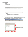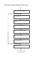
1
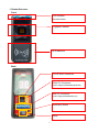
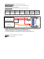
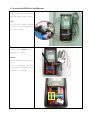
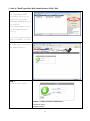
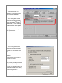
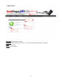
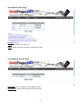
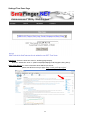
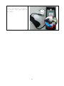
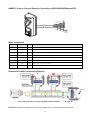
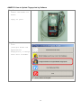
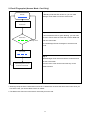
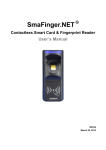
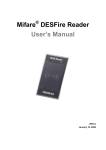
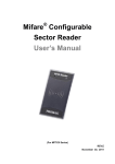
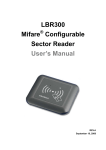
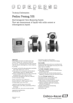
®
SmaFinger.NET
Web-base Application
User’s Manual
(For SF650A Reader)
REV.A
March 21, 2012
Table of Contents
Installation ............................................................................................................................................ 5
1. Reader Structure ................................................................................................................. 6
2. Connect the SF650A on the Ethernet ............................................................................ 8
3. Setup Device Name or Device IP .................................................................................... 9
Application ......................................................................................................................................... 10
1. Link to "SmaFinger.Net® Web Administrator Utility" Site ...................................... 11
2. Add a new user and fingerprints .................................................................................. 12
3. Receive access data from TCP/IP ................................................................................ 14
Instruction .......................................................................................................................................... 18
Login/Logout: ......................................................................................................................... 19
Tools/Remote Door Control Page ..................................................................................... 21
Tools/Buffering Page (Except SF650ASD) ..................................................................... 21
Tools/Record Recover Page (for SF650ASD Only) ...................................................... 22
Tools/Edit User Name Page ................................................................................................ 23
Tools/Change User ID Page ................................................................................................ 23
Tools/Enroll a User Page ..................................................................................................... 24
Tools/Change User ID Page ................................................................................................ 24
Settings/Event Server Page................................................................................................ 25
Settings/New Password Page ............................................................................................ 25
Settings/Time Zone Page .................................................................................................... 26
ANNEX A. How to Change PC/Laptop Network Setting to Support the Auto IP Mode28
ANNEX B. How to Go Back to Default Settings .................................................................... 30
ANNEX C. How to Connect Reader to Controller via RS232/RS485/Wiegand/Tk2 ...... 31
ANNEX D. How to Update Fingerprints by Software............................................................ 32
ANNEX E. How to Update Fingerprints by Manager Card .................................................. 34
ANNEX F. Event Server Detail .................................................................................................... 37
Event Data Structure .................................................................................................................... 37
Record File Format ....................................................................................................................... 38
Record File Path ............................................................................................................................ 38
2
................ 39
3
ANNEX G. History .......................................................................................................................... 40
4
Installation
5
1. Reader Structure
Front
LED Indicator
(Blue/Green/Red)
Fingerprint Sensor
RFID Antenna
Back
TCP/IP RJ45 Connector
White Pin Connector
(Power Supply1/RS232/Wiegand/TK2)
Blue Pin Connector
(Power Supply2/RS485/Relay IO)
Reset-Key Button
Relay
6
TCP/IP RJ45 Connector: Connect to WAS-T0413 for TCP/IP.
White Pin Connector: Connect to WAS-T0132 for RS232/Wiegand/TK2
(refer to page 25)
Blue Pin Connector: (About RS485 Connection please refer to page 25)
VCC
GND
RS485-
RS485+
NC
COM
NO
DC9~12V
Ground
T+
T-
Normal
Close
Common
Point
Normal
Open
Example for Door Lock Connection (for Normal-opened type of Door Lock)
Power Supply
DC12V / 1A
A
EL
Electric
Door Lock
see remark 2
Remark:
1. DO NOT connect power supply from the 8pin connector when you have connected the power
supply from VIN at the 7pin connector to avoid damaging the unit.
2. If the lock requires power to lock (eg. EM lock), connect this point to NC
If the lock requires power to unlock (eg. Electric strike), connect this point to NO
Reset-Key: back to default settings (refer to page 23)
Relay: 3A 120VAC / 3A 30VDC
7
2. Connect the SF650A on the Ethernet
Step 1
Connect SF650A to Ethernet
HUB with (WAS-T0413) cable.
Note:
You can also connect SF650A
to your PC or Laptop directly
with same cable.
Step 2
Connect Power DC12V with
(WAS-T0132) Cable
Remark:
DC12V
The WAS-T0132 can be used for
Power.
Or, you can connect the power
- +
to the PIN VCC and GND (blue
connector of SF650A).
+DC12V
8
3. Setup Device Name or Device IP
Step 1
Use “SmaFinger.NET
®
Discoverer” utility to
search allSmaFinger.NET
®
devices on the network.
(Install
"SmaFingerAppTools.exe"
first. The utility can be
found in the CD disk5406).
Step 2
Click “Refresh” to
refresh the device list.
Step 3
Click “IP Settings” to
change the new device
name.
Step 4
Edit the SF650A device
name for easy
recognition.
Click "Save" to change the
settings.
Notice: If you need use
manual IP, you can click
"Manual" and setup the
correct IP you used.
9
Application
10
1. Link to "SmaFinger.Net® Web Administrator Utility" Site
Step 1
Use “SmaFinger.NET
®
Discoverer Utility” to
search all available
®
SmaFinger.NET devices on
the network.
Click “Web Admin” to go to
the Web Administrator
Utility
Or you can type the Device
Name on browser to link.
Step 2
On Login page, to login to
the SF650A device.
Step 3
Login on the SF650A
Remark: < Default username & password >
Username: admin
Password: admin
11
2. Add a new user and fingerprints
Step 1
1. Login Web Admin Page.
Control
Device with
Internet Browser"
2. Refer to "
Step 2
Click “Enroll A User” on
the "Tools" menu of SF650A
Administrator utility
page.
Step 3
Type in the new user's name
Remark: To assign a specific ID
to the enrolled fingerprint, you
have to click “Save” at the step
7. However, you have to enter a
name in “Name” box at this step
first if you want “Save” action to
be done successfully.
Step 4
Click the “Start Enroll”
to start the enroll
process.
12
Step 5
1. Please put the
fingerprint on reader
twice when blue LED
flash.
2. "Status" will show how
many fingerprints
enroll success.
Step 6
Repeat the Step 4~5 to
Enroll 1~10 fingerprints
for this user (optional).
Step 7
Click the "Save" to finish
a new user adding.
Note:
Click “Stop Enroll” to cancel the enroll process,
Click “Reset” to cancel the enroll process, and delete all fingerprints with this user.
13
3. Receive access data from TCP/IP
Step 1
1. Connect the reader to
Network.
2. Run "Event Server".
In this example:
Local IP=192.168.100.123
Local Port=2168
(Install
"SFEventSetup.exe" first.
The utility can be found in
the CD disk5406)
Step 2
1. Open web browser to link
SmaFinger
®
reader.
2. Login in and click
"SETTINGS"
"Event Server"
14
Step 3
1. Then type in the IP and
Port of Event Server.
2. Click "Save".
Step 4
1. The record data
(buffering) will arrive
at “Event Server” when
user login success by
SmaFinger
®
reader.
Remark: please reference
ANNEX F to get more detail of
“Event Server” record file.
15
Notice:
1.
You can develop your
software to receive data by the
source code in DISK5406.
2.
If no record data arrive at
®
‘SmaFinger.Net Event Server’,
®
please open ‘Mifare /DESFire
®
Reader Utility’, check ‘Buffering
Enable’, and then click ‘Update
Reader’.
Try again login with fingerprint
after update reader.
3.
if no record data arrive at
®
‘SmaFinger.Net Event Server’,
but there has record data arrived
at
Web Admin Site / TOOLS/
Buffering,
and the reader’s connection is
normally connected.
This problem probably because of
the Windows is setting on manual
IP as the right side illustration, but
®
the SmaFinger device is setting
on “Auto Assignment IP”.
The solution is to set the Windows
Default Gateway address,
16
and same to the “SmaFinger
®
Discoverer”, please change IP by
“Manual”, and then set the
Gateway address.
About the more detail of the
gateway address, please check
with your IT for the certainly
information.
17
Instruction
18
Login/Logout:
Logout
User Name
Password
Login
User Name: default name is "admin".
Password: default password is "admin", you can also change the password from "settings".
Login: Click to Login.
Logout: Click to Logout
19
Status Page
Network: display the Reader's Host Name and IP information. IP Mode = Auto or Manual.
SF650A: Number of Users means how many users in this reader. Each user can store 10 fingerprints
Available Fingerprints means this reader remain how many fingerprint memory space to store.
Security Level:
Fingerprint Security Level for FAR (False Acceptance Ratio)
Level
Verification
Identification (1:N)
(1:1)
1~9
10~99
100~999
Normal (Default)
1/10,000
1/10,000
1/100,000
1/1,000,000
1/10,000,000
Secure
1/100,000
1/100,000
1/1,000,000
1/10,000,000
1/100,000,000
1/1,000,000
1/1,000,000
1/10,000,000
1/100,000,000
1/100,000,000
More Secure
Firmware: Reader's firmware version.
20
>=1000
Tools/Remote Door Control Page
Toggle: Click to turn on the relay.
Status: display the relay current status.
Tools/Buffering Page (Except SF650ASD)
Buffering: display current access data in reader. If you have an event server, this data will send out
immediately. Buffering can keep the 32 data on the reader. When restart the reader then data will be
disappear. It will throw the earlier data when record data are over 32.
21
Tools/Record Recover Page (for SF650ASD Only)
Record Recover: For SF650SD, After click “Save”, the “Event Server” will get old records,
then save them automatically.
For example to recover records from November, 2011:
Past
Now
November, 2011
Time Axis
All of the records at this interval will
be recovered in “Event Server”.
22
Tools/Edit User Name Page
ID: User's ID.
Get Unknown: Click to fill an ID which don't have name.
Name: New Name for this user's ID.
Tools/Change User ID Page
Name: User's Name
New ID (Hex): please input user's id in Hex code 4bytes. There are 6 digits in 0~9, A~F.
23
Tools/Enroll a User Page
ID (HEX): User's ID.
Name: New Name for this user's ID.
Status: display how many fingerprint enrolled for this user.
Tools/Change User ID Page
ID or Name: Type in the Name or ID to delete this user.
Get Unknown: Click to fill an ID which don't have name.
24
Settings/Event Server Page
IP Address: the server's IP
Port Number: 1~65535. This number is the same with server listening port.
Settings/New Password Page
New Password: The new password.
Confirm: retype again the new password.
Save: Click to save this password. If your "new password" and "confirm" are different, this button will be
disabled.
Cancel: Click to cancel change password.
25
Settings/Time Zone Page
Time Zone: Select the local time zone for ‘buffering page’ display.
NOTICE: default time zone in " (GMT+8:00)Taipei,Beijing,Perth,Singapore,Hong Kong".
SNTP Time Server: For more information about SNTP Time server,
please visit NTP Pool Project page: http://www.pool.ntp.org/en/
26
For example to Save SNTP Time Server IP (location: Taipei, Taiwan, Asia):
Step1. Visit NTP Pool page, click Active Server > Asia,
And get the pool zone address of Taiwan: tw.pool.ntp.org (or asia.pool.ntp.org)
Step 2. Run MS-DOS command ‘ping [pool zone address]’.
Ex: ping tw.pool.ntp.org
Step 3. If the command send is successful, you will get SNTP Time Server IP.
In this example, SNTP Time Server IP is ‘123.204.45.116’.
Step 4. Key in the IP address: 123.204.45.116 (in this example), then click ‘Save’.
Step 5. Re-power on the reader (optional).
27
ANNEX A. How to Change PC/Laptop Network Setting to Support the Auto IP Mode
Step 1:
Most of the PC/Laptop network
default setting is “Obtain an IP
address automatically” (auto IP
mode). If not, you can follow the
steps to change the network
setting to auto IP mode.
Go to:
Control Panel > Network and Internet
Connections >
Local Area Connection Properties
Step 2:
General select Internet Protocol
(TCP/IP) and click Properties.
Step 3
Select the “Obtain an IP address
automatically.
Then click “OK”.
28
Step 4
Connect the SF650A to PC/Laptop
via Ethernet cable then Power On
To
the SF650A.
Laptop
29
ANNEX B. How to Go Back to Default Settings
When password is lost, forgotten or
need to reset the device to the auto
IP mode.
Reset
Key
You can press the Reset-Key for 5
seconds, the SF650A will reset
automatically and go back to default
setting. The password is “admin” and
IP mode will set to auto IP mode.
Some settings will remain the same when
reset to default:
1. Device name
2. MAC address
3. Reader functions
4. Fingerprint Template database
5. User Data
30
ANNEX C. How to Connect Reader to Controller via RS232/RS485/Wiegand/Tk2
Reader-KIT
ORANGE
BLACK
CP
GND
D1
D0
RX
TX
VCC
WHITE
RED
WAS-T0029
YELLOW
BLUE
GREEN
BROWN
" "
" "
9VDC
Wires Assignment
Color
Symbol
I/O
Description
Red
VCC
IN
Power Input : DC 7.5V~12V
Black
GND
IN
Power Ground
White
DATA 1
OUT
Wiegand Data 1 Signal / ABA TK2 Clock (Strobe)
Green
DATA 0
OUT
Wiegand Data 0 Signal / ABA TK2 Data
Yellow
TXD
OUT
RS232 TXD
(To Host RXD)
Blue
RXD
IN
RS232 RXD
(To Host TXD)
Orange
CP
OUT
Brown
LED/BUZEER
IN
ABA TK2 Card Present
External LED/BUZZER Control
Example for RS485 Connection (Optional)
note 3
* Two ends of wire must connect 120 Ohm terminal resistor
** N up to 32
Remark: More detail information about connection, please refer to "SmaFingerUser’sManual.pdf"
31
ANNEX D. How to Update Fingerprints by Software
Step 1
1. Connect the Reader via
TCP/IP
2. Supply 9V power
Step 2
1. Click
[Configure Reader and
Append/Delete
Fingerprints] to manage
user’s data in Reader.
32
Step 3
1. Check up User in user
list.
2. Or "Select All Users".
3. Click "Readers"
Step 4
1. Click
"Append Fingerprints" to
save selected users’
data to SmaFinger
®
Reader.
* Before Save, you may need
to delete all data from
SmaFinger
®
Reader first.
®
®
Remark: About SmaFinger Card Issuer, please refer to "SmaFinger CardIssuer.pdf".
33
ANNEX E. How to Update Fingerprints by Manager Card
1. Enroll Fingerprint (Access Mode: Finger Only)
Step 1
In Standby mode the LED is blue on, you can read
Standby
Manager Enroll Card to enter the enroll mode
Read Manager
Enroll Card
Step 2
In enroll mode the LED is green blinking, you can read
Read Card
the User Card to store the card UID or Sector Data and
Manager Card
enter the scan mode.
Or read Manager Enroll Card again to exit the enroll
mode.
User’s Card
Step 3
Scan Fingerprint
In scan mode the LED is blue blinking, please scan
user’s fingerprint till beeper sound, the LED will become
green on.
Scan same
Fingerprint again
Scan the same fingerprint again till beeper sound,
the LED will become blue blinking.
Step 4
Continue step 3 to scan second fingerprint with the
Scan Second
Fingerprint?
Yes
same card UID or Sector Data if needed.
(The same card UID or Sector Data can enroll up to 10
fingerprints)
No
Read Manager Enroll Card
to exit the enroll mode.
Or read Manager Enroll Card to finish the enrollment
and exit the enroll mode.
Then the user can use fingerprint only on the SF600
enrolled. The card can be used card-only on the SF600
enrolled.
Remark:
1. Warning! Keep the User Card and do not lose it! To delete user must use the same User Card. Once you
lose User Card, you cannot delete user from reader.
2. For multi-user, please use the Multi-User Card to create serial number automatically.
34
2. Enroll Fingerprint (Access Mode: Card Only)
Step 1
In Standby mode the LED is blue on, you can read
Standby
Manager Enroll Card to enter the enroll mode
Read Manager
Enroll Card
Step 2
In enroll mode the LED is green blinking, you can read
Read Card
User’s Card
the User Card to store the card UID or Sector Data and
Manager Card
enter the scan mode.
Or read Manager Enroll Card again to exit the enroll
mode.
Scan Mode
Step 3
Read Manager Enroll Card to finish the enrollment and
exit the enroll mode.
Read Manager Enroll Card
to exit the enroll mode.
Then the user's card can be used card-only on the
SF600 enrolled.
Remark:
1. Warning! Keep the User Card and do not lose it! To delete user must use the same User Card. Once you
lose User Card, you cannot delete user from reader.
2. The Multi-User Card cannot be used for Card Only access mode.
35
3. Delete Fingerprint for deletion
Step 1
In Standby mode the LED is blue on, you can read
Standby
Manager Delete Card to enter the delete mode
Read Manager
Delete Card
Read Card or Put
user's fingerprint
Step 2
Manager Card
In delete mode the LED is red blinking, you can read the
User Card to delete the user’s all fingerprints with UID or
User’s Card
put user's fingerprint to delete the user's all fingerprints.
After deletion to exit the delete mode.
Deleting
(LED OFF)
Or read Manager Delete Card again to exit the delete
mode.
Remark:
To DELETE the user's fingerprints which are enrolled by the Multi-User Card, it is necessary to put user's
fingerprint in Delete Mode.
36
ANNEX F. Event Server Detail
Event Data Structure
TCP Port Number: 2186 (Default)
TCP Data Payload (Event Packet) :
TCP
Data Payload
Header
Event Data
Fields
Size (Byte)
Description
Time
4
Time Value (Long Integer Type)
Data Type
1
1 = MIFARE UID
2 = DESFIRE UID
3 = 125K UID
4 = MIFARE SECTORE
9 = UNKNOW UID
Data Size
1
0~16
Data Buffer
16
Card UID or Sector Data
Name
16
Name (String Type)
XID
4
The XID of the login device
37
Record File Format
File Name:
[Year]_[Month].log
File Content:
[IP Address], [Date and Time], [User ID], [User Name], [Time source]
*Remark:
[Date and Time]
[Time source]
YYYY / MM / DD hh:mm:ss (default)
Time source means SNTP time (via internet) or local PC time.
Record File Path
You can change the path by clicking
and then assign a specified path that you want.
The records will be saved as a log file automatically in this folder every month.
38
Event Server Software Data Receive Flow Chart:
Initial the listener (Winsock item).
Reader makes a connection request
to the listener.
Receiver (Winsock item) accepts the
request.
Data arrival at the receiver.
Receiver gets the arrival data.
Store the arrival data.
Close the receiver.
Close the listener.
END
39
ANNEX G. History
REV.A: February 07, 2012 (Kylie)
Issue.
February 22, 2012 (Kylie)
Move the record file remark(p.13) to ANNEX F, and change ANNEX number.
February 24, 2012 (Kylie)
Add event server S/W data recevice flow chart. (p.35)
February 29, 2012 (Kylie)
Add event data structure “XID” description. (p.33)
March 21, 2012 (Kylie)
Re-typesetting.
Add the solution about event server can’t get the attendance records.(p.14)
40
PROMAG
®
GIGA-TMS INC.
http://www.gigatms.com.tw
mailto:[email protected]
TEL : +886-2-26954214
FAX : +886-2-26954213
Office: 8F, No. 31,Lane 169, Kang-Ning St., Hsi-Chih, Taipei, Taiwan
41