1
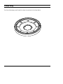
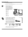
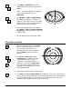
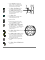
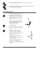
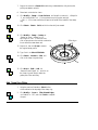
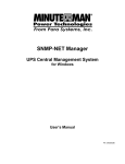
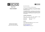
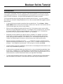
Boolean Solids Tutorial
Introduction
The CADMAX Solid Master Tutorial is a great way to learn about the benefits of constructive (boolean)
solid modeling with CADMAX. We have assembled four typical parts that you will be able to construct
using CADMAX Solid Master. Each part should take between 20-40 minutes to complete.
The tutorial assumes that you already have some familiarity with CADMAX. In you are unfamiliar
with CADMAX, review the Getting Started section first. Here are several additional suggestions before
getting started:
!
In the tutorial there are several conventions that are used with text. The text Draw > Circle >
Center Radius means to click on the Draw menu, hold the cursor over the Circle function until the
Circle sub-menu pops, then click on Center Radius.
!
When you see a statement that starts with the word “set”, this means you are to set a modifier
value in the currently displayed Function box. For example, in the Line function box, you will see
a -Connect? modifier. When you see the statement, “Set -Connect? to off”, this means you
should set it off by clicking on the word Connect if it isn’t already off.
!
Sometimes you will be asked to set a specific value for a modifier. For example, in the Circle
Function box you will see a modifier called -Radius? with a combo box below it and a history
arrow. When you see the statement, “Set -Radius? to .25”, this means you should click in the
-Radius? text field and type in the value or use the history arrow to select previous value.
!
When an instruction includes an arrow key ( 6 7 8 9) followed by a number, hold down the Ctrl
key before pressing the specified arrow. For example, <Ctrl+6>1 means hold down the Ctrl key
and press 6, then release the keys and press 1. After you type in the value, press Enter.
!
Context sensitive prompts are available for each function in the message area at the bottom of the
screen. Help is available buy pressing F1.
!
In the tutorial, we recommend when you should zoom in or out on the drawing to get better views
of your work. In addition to our recommendations, you should feel free to use the View menu to
Zoom around the drawing as you feel is appropriate. Press F10 to go to previous zooms or F11 to
make a new zoom or use the View shortcut icons on the right side of the display.
!
To load a specified drawing, press F4 to Open a drawing. The drawings that you will be asked to
open are located in the \SAMPLES sub-folder under the folder that you installed CADMAX.
CADMAX User's Manual
Boolean Solids Tutorial / 1
Clamp Ring
The first solid drawing you will model is a clamp ring as shown in the figure below.
2 / Boolean Solids Tutorial
CADMAX User's Manual
Draft Clamp Ring Profile
1.
Open the drawing CLAMPRNG.
2.
Click on Edit > Surfaces and boolean solids or click on the 3D icon on the Ribbon
bar.
3.
Starting in the left side of the front
view, draft the profile in the
illustration. Click Draw > Line,
click on a start point for the lower
left corner of the profile, then type
the following pressing Ctrl before
pressing on any of the arrow keys,
and press Enter after each entry:
<Ctrl+6>4.5
<Ctrl+8>.25
<Ctrl+7>2
<Ctrl+8>.5
<Ctrl+7>1.5
<Ctrl+8>.5
<Ctrl+7>.25
<Ctrl+9>1
<Ctrl+7>.5
<Ctrl+8>1
<Ctrl+7>.25
<Ctrl+9>1.25
4.
Click Draw > More Lines > 1 Pt Construction,
set -System? to ‘model’, -Construction Size? to
‘fill view’, -Angle? to ‘90', -Geometry
Attribute?* to ‘Centerline’. Click in about the
center of the front view to place a centerline.
Centerline
* Note: Set the Geometry Attribute from the
Ribbon bar. Click on the Geometry attribute
combo box arrow and select the Geometry
attribute from the list of available attributes.
Make sure the centerline is on the same plane as the profile.
5.
CADMAX User's Manual
Set -Geometry Attribute? to ‘sheet_metal’.
Boolean Solids Tutorial / 3
6.
Click Select > Select All In and using a
rubberband box fully enclose the profile to
select it.
Note: You can also right click to display a
Pop Up menu and then click on
Select All In.
7.
Click Modify > Sweep > Rotate Surfaces,
set -Sweep? to ‘ends-only’, -#Steps? to ‘1', Angle? to ‘360', -With? to ‘arcs’, and -Make
Solids? to ‘yes’. Click on any two points on
the centerline to create the solid.
8.
Notice the original profile is still selected.
Click Select > Select > Surfaces of Selected
Boundaries to select the surface made by the
original profile.
9.
Click Erase to remove the original profile.
Place Holes in Profile
1.
Zoom in on the top view. Use the Zoom
2D icon located in the Quick Tool bar
on the right side of the screen. If
necessary, when the zoom is complete,
click on Resume or click on another
function.
2nd Circle
2.
Click Draw > More Lines > 1 Pt
Construction, set -System? to ‘model’,
-Construction Size? to ‘fill view’,
-Angle? to ‘0', -Attribute Name? to
‘centerline’. Click on the Center point
icon in the Quick Snap tool bar on the
right side of the display and click on the
second smallest circle.
3.
Set -Attribute Name? back to ‘sheet_metal’.
4.
Click Draw > Circle > Center, Radius, set -Radius? to ‘.125', set -Circle Plane? to
‘view’, and click on the intersection of the construction line and the circle as shown
in the previous illustration. Set -Radius? to ‘.25', and press Enter to insert the
second circle at the same center point as the first circle.
4 / Boolean Solids Tutorial
CADMAX User's Manual
5.
Use the Zoom 2D icon located in the
Quick Tool bar on the right side of the
screen to zoom in on the two circles that
you just inserted into the drawing.
6.
Click Select > Select Element, and click
on the larger radius circle just added.
7.
Click Modify > Move or Copy, set -Move
Which? to ‘nocopy’. Click anywhere as a
pick up point and type <Ctrl+R>1 as
the put down point.
8.
Click Select > Clear.
9.
Repeat steps 6-7 for the smaller radius
circle moving a distance of .38.
10. Select both circles.
11. Zoom back out to show the four views.
Click on the Previous icon located in the
Quick View tool bar on the right.
12. Click Modify > Sweep > Linear, Surfaces,
set -Sweep? to ‘ends-only’, -# Steps? to ‘1',
and -Make Solids? ‘on’. Click anywhere as a
pick up point and type <Ctrl+T>1 to
create two solids.
13. Click Select > Select > Solid and click on the
two solids just created.
14. Click Modify > Sweep > Rotate, set -Sweep?
to ‘none’, -# Steps? to ‘8', and -Angle? to
‘360'. In the front view, click on any two
points on the vertical construction line to
define the rotate about axis.
15. Click Erase to remove the original swept
profiles.
16. Click Select > Select > All Editable Levels or
press Ctrl+A.
CADMAX User's Manual
Boolean Solids Tutorial / 5
17. Click Select > Unselect > Solid, and click on the clamp ring main body.
18. Click Draw > Solid > Subtract, and click on the clamp ring main body to put a
circular array of holes in the clamp ring.
Add Clamp Ring Guides
1. In the top view Select the construction line.
2. Click Modify > Move or Copy, set -Move
Which? to ‘nocopy’. Click anywhere as a
pick up point and type <Ctrl+T>.5 to
move the construction line to the depth of
inner ring.
Note: You can also Select, Clear, Erase,
Move and Copy geometry by right clicking
to display the Pop up menu and then
selecting the desired function.
3. Click Select > Clear.
4. Zoom in on the intersection of the smallest
circle and the construction line on the right
side.
5. Click Draw > Line and click on the
intersection of the inner circle and the
construction line to create a reference point.
6. Click Draw > Line again and type
<Ctrl+7>.5
<Ctrl+6>.5,<Ctrl+PageDown>.25
<Ctrl+PageUp>.5
Complete the profile by drawing a line to point
1 as shown in the figure.
2
1
3
Note: Just as the arrow keys are used for
relative XY, <Ctrl+PageUp> and
<Ctrl+PageDown> are used to denote relative
Z distances.
6 / Boolean Solids Tutorial
CADMAX User's Manual
7. Right click and click on Select All In and using a rubberband box fully enclose the
profile just added to select it.
8. Zoom back out to the four views.
9. Click Modify > Sweep > Linear Surfaces, set -Sweep? to ‘ends-only’, -# Steps? to
‘1', and -Make Solids? ‘on’. Click anywhere as a pick up point and type
<Ctrl+9>.25 to create a solid that is equal to the width of the bottom of the clamp
ring.
10. Click Select > Select > Solid, and click on the solid just created.
11. Click Modify > Sweep > Rotate, set
-Sweep? to ‘none’, -# Steps? to ‘12',
and -Angle? to ‘360'. In the front view,
click on two points on the vertical construction
line to define the rotate about axis.
Fillet edges
12. Right click, then click Erase to remove
the original swept profile.
13. Type Ctrl+A to Select All Editable.
14. Click Select > Unselect > Solid, and
click on the clamp ring main body.
15. Click Draw > Solid > Add, set
-Remove Excess Edges? ‘on’, and click on
the clamp ring main body to make the
guides part of the main body.
Add Clamp Ring Fillets
1. Using the previous illustration, Select the four
circles marked on the top edge of the clamp ring.
2. Click Modify > Corner > Fillet Selected Edges,
set -Radius? to ‘.125', and click Finish to complete
the part.
CADMAX User's Manual
Boolean Solids Tutorial / 7
8 / Boolean Solids Tutorial
CADMAX User's Manual
CADMAX Solid Master Tutorial
9