1
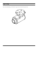
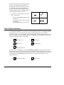
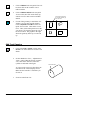
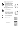
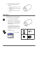
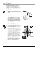
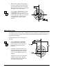
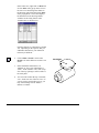
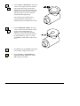
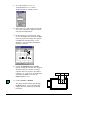
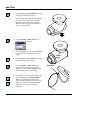
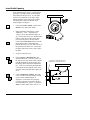
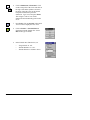
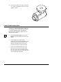
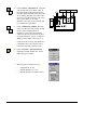
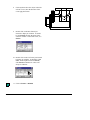
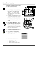
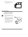
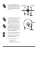
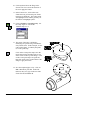
Pipe Cavity Tutorial
Introduction
The CADMAX Solid Master Tutorial is a great way to learn about the benefits of feature-based parametric
solid modeling with CADMAX. We have assembled several typical parts that you will be able to construct
using CADMAX Solid Master. Each part should take between 20-40 minutes to complete.
The tutorial assumes that you already have some familiarity with CADMAX. If you are unfamiliar with
CADMAX, review the Getting Started section first in CADMAX Help or in the CADMAX Users Manual.
Here are several additional suggestions before getting started:
!
In the tutorial, there are several conventions that are used with text. The text Draw > Circle > Center
Radius means to click on the Draw menu, hold the cursor over the Circle function until the Circle submenu pops, then click on Center Radius.
!
Most functions are available through drop-down menus and icon tool bars. Throughout the tutorials the
written instructions tell you how to do things from the drop-down menus and the icons to the left show
you how to accomplish the same operation using icons. The first icon is the icon to click on the main
tool bar, and the second indented icon is the icon on the vertical function bar.
< Locate this icon on the top tool bar and click on it.
< Then click on this icon on the vertical tool bar that pops up on the left side.
!
When you see a statement that starts with the word “set”, this means you are to set a modifier value in
the currently displayed Function box. For example, in the Line function box, you will see a -Connect?
modifier. When you see the statement, “Set -Connect? to off”, this means you should set it off by
clicking on the word Connect if it isn’t already off.
!
Sometimes you will be asked to set a specific value for a modifier. For example, in the Circle Function
box you will see a modifier called -Radius? with a combo box below it and a history arrow. When you
see the statement, “Set -Radius? to .25”, you should click in the -Radius? text field and type in the value
or use the history arrow to select previous value.
!
When an instruction includes an arrow key (6 7 8 9) followed by a number, hold down the Ctrl key
before pressing the specified arrow. For example, <Ctrl+6>1 means hold down the Ctrl key and press 6,
then release the keys and press 1. After you type in the value, press Enter.
!
Context sensitive prompts are available for each function in the message area at the bottom of the screen.
Help is available buy pressing F1.
CADMAX User's Manual
Solids Tutorial / 1
!
In the tutorial, we recommend when you should zoom in or out on the drawing to get better views of your
work. In addition to our recommendations, you should feel free to use the View menu or the Quick View
toolbar to zoom around the drawing as you feel is appropriate. Press F10 to go to previous zooms or F11
to make a new zoom.
!
To load a specified drawing, press F4 to Open a drawing. The drawings that you will be asked to open
are located in the \SAMPLES sub-folder under the folder that you installed CADMAX.
2 / Solids Tutorial
CADMAX User's Manual
Pipe Cavity
The second solid drawing you will model is a pipe cavity as shown in the figure below.
CADMAX User's Manual
Solids Tutorial / 3
Opening a Sketch
1.
Open the drawing FEATURE.CXS from the
/SAMPLES folder which is a subfolder
under the folder you installed CADMAX.
2.
Click on Edit > Feature Modeling or click
on the Feature Modeling icon on the Ribbon
bar.
The first feature of the part is going to be an
extruded cylinder. You will start by sketching a
profile of the cylinder on a work plane and
extrude it to give it thickness.
3.
Click on Edit > Sketch or click on the
Sketch icon on the ribbon bar. This starts a
new sketch and displays the Work Plane
function box.
The Work Plane function box shows
different methods to locate the sketch plane,
depth, rotation and twist.
Once the work plane is defined, the Sketch
function bar will open and place you in the
Sketch Line function. The Sketch function
bar contains many of the functions you will
use to draw and dimension a sketch.
4.
Set the -Method? to ‘View’ and click on the
front view (lower left). Now, no matter
which view you work in, as you sketch your
object, the geometry will always be oriented
to the front view.
5.
Click on Draw > Sketch Circle. Working
in the front view, draft a circle by clicking
on the center point, drag the cursor away
from the center and click to place the circle.
4 / Solids Tutorial
CADMAX User's Manual
Adding Dimensions
Dimensions are used to make the geometry the desired size. CADMAX does not require that you
add dimensions before you extrude the model. You can always return to the sketch and add
dimensions or change the sketch later in the design.
1.
Click on Dimension > Radial.
2.
Click on the circle. Drag the cursor to the
desired text position and click to place the
dimension.
3.
Type in 5 and press Enter. This assigns a
value of 5 for the dimension and
automatically resizes the circle according to
the assigned value.
You can always change this value at a later
time using the Equation function.
Extrude the Circle
The first feature in a part is called the base.
1.
Click on Feature > Extrude Sketch or
click on the Extrude Sketch icon on the top
tool bar.
The Extrude Base dialog box appears so you
can specify the type and distance of the
extrusion.
2.
Set -Extrude Distance? to ‘15' and -Extrude
Extent? to ‘Distance Above’.
CADMAX User's Manual
Solids Tutorial / 5
The extrusion takes place toward the point that
you click. The direction of the extrusion is
defined by the side of the sketch that you click
on. Working in the top view (top left), if you
click above the circle, then the extrusion will
take place in that direction. Clicking below the
circle brings the extrusion toward you.
3.
In the top view, click anywhere below the
circle. Notice that:
•
•
•
The new feature, Base1, appears in the
Feature tree.
The top level function bar has changed
for Modeling.
The sketch was extruded in each view.
Set the Display Preferences
You change the orientation of a view or how a view is displayed in order to see boundaries that are
not visible in a view. The 3D Quick View tool bar on the right side of the screen contains
functions to change a view to wireframe, hidden, hidden-dashed, shaded or unshaded. Following
are the icons that permit you to change how a view is displayed. To operate these functions, click
on the icon, then click on the view to change.
Wireframe View
Shaded View
Hidden View
Unshaded View
Hidden dashed View
To rotate a view, use dynamics. Click on the Dynamic View Roll icon, then click on the view to
roll, then click on a roll about point to start the roll. Normally, the roll about point is on geometry
in the model. Drag the cursor in the direction of the roll and click again to anchor the view at the
new orientation. Use Previous View in the 3D Quick View tool bar to return the view to its
original orientation.
Dynamic View Roll
6 / Solids Tutorial
Previous View
CADMAX User's Manual
1.
Click on Hidden in the 3D Quick View tool
bar, then click on the isometric view to
make it hidden.
2.
Click on Hidden-dashed in the 3D Quick
View tool bar, then click on the front, top,
and side views to make each view hiddendashed.
3.
Use Dynamic View Move
to move the geometry up
in the top view.
If some of the geometry is outside the view
window, you can easily pan the window.
Click on Dynamic View Move in the 3D
Quick View tool bar. Click on the view to
move. Then, click on the point to move the
view about. Click again to place the view at
the new location. The graphic to the right
shows the geometry in the top view moved
up.
Add Front Opening
1.
Click on the Edit > Sketch or click on the
Sketch icon on the ribbon bar to start a new
sketch.
2.
Set the -Method? to ‘Face’, -Adjustment? to
‘None’, and in either the front or isometric
view, click on the front face of the base
cylinder as indicated in the figure.
Click on this face
As you wave the cursor over the object, the
face that will be selected displays in red.
Make sure the front face is red before you
click on it.
3.
Zoom in on the front view.
CADMAX User's Manual
Solids Tutorial / 7
The smaller opening is going to be centered on
the front face. It will have a radius of 3.
4.
Click on Draw> Sketch Circle. Wave the
cursor over the edge of the circle until the
center point of the circle pops up in the
display, then click on the center point and
drag the cursor away from the center point
and click to place a circle smaller than the
original circle.
The circle has been constrained to be concentric
with the original circle. A dimension needs to be
added for the radius.
5.
Click on Dimension > Radial.
6.
Wave the cursor over the smaller circle
until it turns red and an echo of the radial
dimension is displayed. Click on the circle,
drag the cursor to locate the text, and click
to place the radial dimension. Type in 3 and
press Enter to set the radius of the circle to
3.
7.
Press F10 or click on Previous in the Quick
View tool bar to display the four views.
8.
Click on Feature > Extrude Sketch to
display the Extrude function box. Select
Boss as the type of extrude.
9.
In the Extrude Boss function box, set:
•
•
•
8 / Solids Tutorial
-Target Solids? to ‘All’
-Extrude Distance? to ‘3’
-Extrude Extent? to ‘Distance Above’
CADMAX User's Manual
10. Click anywhere below the object in the top
view to show the direction of the boss.
Notice that:
•
•
•
The new feature, Boss1, appears in the
Feature tree.
The top level function bar has changed
for Modeling.
The front cylinder has been added to
the base.
Shell Cylinder
The Shell feature is used to remove specified
faces of an object and to set a wall thickness.
1.
Click on Select > Select Element.
2.
In the isometric view, click on the surface
identified by the “P” in the figure shown at
right. Make sure you click on the surface
and not the edge. If necessary, zoom in to
select the surface.
P
As you click the surface, its boundary
geometry will turn yellow and a surface tag
will be displayed. In this case, since the
selected surfaces were planes, the surface
tag is a “P”.
3.
Click Feature > Shell.
4.
Set -Thickness? to ‘1' and click Finish.
CADMAX User's Manual
Solids Tutorial / 9
Create Top Opening
The top opening is going to be created using a
360 degree Swing feature. The center of
opening is 4.5" from the rear of the main
cylinder. The work plane for the profile of the
opening needs to be offset 4.5" from the rear of
the main cylinder.
1.
Click on the Edit > Sketch or click on the
Sketch icon on the ribbon bar to start a new
sketch.
2.
In the Work Plane function box, set the
-Method? to ‘Front’, -Adjustment? to
‘None’ and the -Offset? to ‘4.5'. In either
the top or isometric view, click on the rear
edge of the base cylinder as indicated in the
figure. The work plane will be oriented to
the front view and offset 4.5 from the rear
of the main cylinder.
3.
Zoom in on the front view.
4.
Click on Draw > Sketch Line. Working in
the front view, draw a profile similar to the
one shown in the figure.
Start the profile at the center point of the
circle. Wave the cursor over the center point
of the circles to display the horizontal and
vertical dynamic construction lines.
As you work, use the dynamic construction
lines as guides to help you make vertical
and horizontal lines. For the last point, you
may have to wave the cursor over the center
point again to get the construction line in
order to make the proper snap. As you
draw the profile, make sure none of the
points snap to circle edges, otherwise, the
point will be constrained to the edge.
10 / Solids Tutorial
CADMAX User's Manual
5.
When you are creating a Swing feature, a
line must be added to the sketch defining
the axis that the profile will swing about.
The swing axis is going to be a vertical line
through the center of the cylinder.
Click on Draw > Sketch Line, then click
on Centerline in the Line function box.
Continuing to work in the front view, click
on the center point of the circles and click
on any point on the vertical dynamic
construction line to make a vertical
centerline.
Adding Dimensions
Use dimensions to size the geometry. CADMAX does not require that you add dimensions before
you extrude the model. You can always return to the sketch and add dimensions or change the
sketch later in the design.
Add the dimensions shown in the figure to
the right.
1.
Click on Dimension > Horizontal.
Double-click on the top edge of the
profile. Drag the cursor to the desired
text position and click to place the
dimension.
CADMAX automatically snaps to the
end points of the line when you doubleclick unless the midpoint is under the
cursor. Then, CADMAX snaps to the
midpoint.
Alternatively, click once on each of the
endpoints of the top edge. Drag the
cursor to the desired text position and
click to place the dimension.
CADMAX User's Manual
Solids Tutorial / 11
2.
Type in 6.25 and press Enter. This assigns
a value of 6.25 for the dimension and
automatically resizes the profile according
to the assigned value.
3.
Double-click on the bottom edge of the
profile. Drag the cursor to the desired text
position and click to place the dimension.
Type in 3.75 and press Enter. This assigns
a value of 3.75 for the dimension and
automatically resizes the profile according
to the assigned value.
4.
Click on Dimension > Vertical. Doubleclick on the upper left edge of the profile.
Drag the cursor to the desired text position
and click to place the dimension. Type in
1.37 and press Enter. This assigns a value
of 1.37 for the dimension and automatically
resizes the profile according to the assigned
value.
5.
Click on the end-points of the right edge of
the profile (Note: Since the Centerline is
there you cannot double-click because it
may result in the wrong points). Drag the
cursor to the desired text position and click
to place the dimension. Type in 9.15 and
press Enter. This assigns a value of 9.15
for the dimension and automatically resizes
the profile according to the assigned value.
12 / Solids Tutorial
CADMAX User's Manual
Swing Profile
1.
Click on Feature > Swing Sketch or click
on the Swing Sketch icon on the main tool
bar.
2.
Set -Boolean Choices? to ‘Boss’.
3.
In the Swing Boss function box, set -Target
Solids? to ‘All’ and -Rotation Angle? to
‘360'. Click anywhere in a view to apply
the Swing feature.
Insert Hole in Top Opening
The top opening is going to have a 1.75 hole
into the main cylinder. In order to assure that
the hole is always through the entire top
opening, its extrude distance needs to be equal
to the height dimension in the previous profile,
which was 9.15.
1.
Determine the name assigned to the 9.15
dimension. Click on the Variables icon on
the ribbon bar to display the variables table.
CADMAX User's Manual
Solids Tutorial / 13
In the feature tree, right-click on Boss2 and
click on Show in the pop-up menu or wave
the cursor over the Swing Boss feature in
the drawing, right-click and click on Show
in the pop-up menu. This action displays
the dimensions in the drawing and the
variables for the Swing feature in the
Variables table as shown below.
From the table the 9.15 dimension is named
‘d4'. Depending on the sequence that you
added these dimensions, your dimension
name may be different.
2.
Click on Edit > Sketch or click on the
Sketch icon on the ribbon bar to start a new
sketch.
3.
In the Work Plane function box, set
-Method? to ‘Face’ and -Adjustment? to
‘None’. In the isometric view, click on top
face of the top opening to set this surface as
the work plane.
4.
You can work in either the top or isometric
view. Zoom in on one of the two views. If
you are going to work in the top view, you
may want to change it from ‘hiddendashed’ to ‘hidden’.
14 / Solids Tutorial
Work Plane
CADMAX User's Manual
5.
Click on Draw > Sketch Circle. Wave the
cursor over the edge of the circle until the
center point of the circle pops up in the
display, then click on the center point and
drag the cursor away from the center point
and click to place a new circle which is
smaller then the original circle.
The circle has been constrained to be
concentric with the original circle. A
dimension needs to be added for the radius.
6.
Click on Dimension > Radial. Wave the
cursor over the circle until it turns red and
an echo of the radial dimension is
displayed. Click on the circle, drag the
cursor to locate the text and click to place
the radial dimension. Type in 1.75 and
press Enter to set the radius of the circle to
1.75.
7.
Press F10 or click on Previous in the Quick
View toolbar to display the four views.
8.
Click on Feature > Extrude Sketch to
display the Extrude function box. Select
Cut as the type of extrude.
CADMAX User's Manual
Solids Tutorial / 15
9.
Set -Target Solids? to ‘All’, set
-Extrude Distance? to ‘5’ and set
-Extrude Extent? to ‘Distance Above’.
10. In the front view, click anywhere below the
face of the work plane to apply the extrude
and create the Cut1 feature.
11. On the feature tree or the drawing, rightclick on the Cut1 feature and click on Show
in the pop-up menu to display the variables
for Cut1 in the Variables table. As an
alternative, you can double-click Cut1 to
display its variables.
12. Click in the Equation field for Extru3.
Instead of using the value that was assigned
when the feature was created, we always
want the value to be equal to ‘d4' which is
currently 9.15. Type in ‘d4' in the equation
field and press Enter. The value for
Extru3 updates to 9.15.
13. Click on Feature > Rebuild.
The model rebuilds with the hole through
the Boss2 feature. Even if the dimension
changes, the hole will always go through
the feature.
16 / Solids Tutorial
CADMAX User's Manual
Add Fillets
1.
Click on Select > Select Element and click
on the edges shown in the figure.
Notice that the edges and surfaces highlight
in red as you move the cursor over them
identifying which item will be selected.
Make sure only the edges are highlighted
when you click on them.
2.
Click on Feature > Fillet, Fixed. The
Fillet function box appears.
3.
Set -Fillet Radius? to ‘.25' and click Finish
to apply the fillet feature to the selected
edges.
4.
Click on Select > Select Element and click
on the edge shown in the figure.
5.
Click on Feature > Fillet, Fixed. The
Fillet function box appears. Set -Fillet
Radius? to ‘.625' and click Finish to apply
the fillet feature to the selected edge.
6.
In the Quick 3D View tool bar on the right
edge of the display, use Dynamic Roll
View to view the model from the rear.
Notice that the model blends where the two
fillets meet. Then, use Previous View to
change the view back to its original
orientation.
CADMAX User's Manual
Select
edge
Fillet blends
Solids Tutorial / 17
Insert Outlet Opening
In the following steps, insert a .5 inside radius
opening at a 45 degree angle when looking at
the model from the front view. A work plane
needs to be constructed at a 45 degree angle
starting from the center of the main cylinder.
The work plane is based off the side view,
rotated negative 45 degrees.
1.
Click on the Edit > Sketch or click on the
Sketch icon to start a new sketch.
2.
In the Work Plane function box, set the
-Method? to ‘View’, -Adjustment? to
‘Origin’, and set the -Rotation Angle? to ‘45'. Click on the side view to determine the
plane to rotate from. Notice in the other
views how the plane is already rotated.
Click on the Center Point snap icon in the
Quick Snap tool bar on the right edge,
position the cursor over one of the circles of
the cylinder in the front view. Notice that
the plane snaps to the center, click to place
the plane.
3.
Zoom in on the side view.
4.
Click on Draw > Sketch Circle in the
Sketch function bar. Wave the cursor over
the edge of one of the circles of the cylinder
until the midpoint of the circle pops up in
the display and its horizontal construction
line. Click on a point along the horizontal
construction line and drag the cursor away
from the center point and click to place the
circle.
5.
Use dynamic construction lines from
midpoint of arc to position the circle
Click on Dimension > Radial. Wave the
cursor over the circle until it turns red and
an echo of the radial dimension is
displayed. Click on the circle, drag the
cursor to locate the text and click to place
the radial dimension. Type in .75 and press
Enter to set the radius of the circle to .75.
18 / Solids Tutorial
CADMAX User's Manual
6.
Click on Dimension > Horizontal. Click
on the center point of the circle and click on
the edge of the main cylinder as shown in
the figure. Drag the cursor to the desired
text position and click to place the
dimension. Type in 2.25 and press Enter.
This assigns a value of 2.25 for the
dimension and automatically positions the
circle.
7.
Press F10 or click on Previous in the Quick
View tool bar to display the four views.
8.
Click on Feature > Extrude Sketch to
display the Extrude function box. Select
Boss as the type of extrude.
9.
In the Extrude Boss function box, set:
•
•
•
CADMAX User's Manual
-Target Solids? to ‘All’
-Extrude Distance? to ‘10.3’
-Extrude Extent? to ‘Distance Above’
Solids Tutorial / 19
10. Click anywhere above the object in the front
view to show the direction of the boss and to
apply the feature.
Create Outlet Opening Hole
To insert a .5 radius hole through the outlet, you
will reuse the previous work plane and extrude a
.5 circle through the object. The extrusion
distance will be assigned the name of the 13.3
extrusion just inserted.
1.
Click on the Edit Sketch or click on the
Sketch icon on the ribbon bar to start a new
sketch.
2.
Set the -Method? to ‘Sketch Plane’.
Position the cursor over the geometry of the
outlet feature just inserted until the work
plane for the feature echos, then click to
reuse that work plane for the new feature.
3.
Click on the Hidden-dashed icon on the
Quick 3D View tool bar and click on the
side view to make the view hidden-dashed,
if it isn’t already. Zoom in close on the side
view as indicated in the figure.
20 / Solids Tutorial
CADMAX User's Manual
4.
Click on Draw > Sketch Circle. Using the
center point of the circle shown, click on
the center point and drag the cursor away
from the center point and click to place the
circle, making sure that your radius of the
new circle is not the same size as the circle
whose center point you are using.
Otherwise, the circle you are inserting will
be constrained to equal radius.
5.
Click on Dimension > Radial. Wave the
cursor over the circle until it turns red and
an echo of the radial dimension is
displayed. Click on the circle, drag the
cursor to locate the text and click to place
the radial dimension. Type in .5 and press
Enter to set the radius of the circle to .5.
It isn’t necessary to assign any additional
constraints to the circle, because it has a
concentric constraint to the first circle.
6.
Click on Feature > Extrude Sketch to
display the Extrude function box. Select
Cut as the type of extrude.
7.
In the Extrude Cut function box, set:
•
•
•
CADMAX User's Manual
-Target Solids? to ‘All’
-Extrude Distance? to ‘10.3’
-Extrude Extent? to ‘Distance Above’
Solids Tutorial / 21
8.
Click anywhere above the object in the side
or front view to show the direction of the
cut to apply the feature.
9.
Double click on the Boss feature just
inserted to display its variables. It should
be called Boss2 and note the name of the
extrusion variable. In the table below, it is
Extru4.
10. Double click on the Cut feature just inserted
to display its variables. It should be called
Cut2. In the Equation field for Extru5,
enter Extru4 so that the two values will
always be identical.
11. Click on Feature > Rebuild.
22 / Solids Tutorial
CADMAX User's Manual
Remove Excess Geometry
The inside of the main cylinder contains excess
geometry that must be removed. Use an Extrude
Cut feature to remove the geometry.
1.
Click on the Sketch icon on the ribbon bar.
2.
Set the -Method? to ‘Front’, -Adjustment?
to ‘None’ and click on the inside edge of the
main cylinder as shown. By setting the
-Method? to ‘Front’, you can orient the
plane to the front view and set the depth
with a single click.
3.
Press F10 or click on Previous in the Quick
View tool bar to display the four views and
then zoom in on the front view. Click on
the Hidden-dashed icon on the Quick 3D
View tool bar and click on the front view to
make the view hidden-dashed, if it isn’t
already.
4.
Click on Draw > Sketch Circle. Click on
the center point of one of the shown circles,
drag the cursor away from the center point
until it is the same radius as the circle
shown and click to place the circle. This
constrains the circle to have an equal radius
to the inside of the main cylinder.
5.
Press F10 or click on Previous in the Quick
View tool bar to display the four views.
6.
Click on Feature > Extrude Sketch to
display the Extrude function box. Select
Cut as the type of extrude.
7.
In the Extrude Cut function box, set:
•
•
•
CADMAX User's Manual
-Target Solids? to ‘All’
-Extrude Distance? to ‘13’
-Extrude Extent? to ‘Distance Above’
Solids Tutorial / 23
8.
Click anywhere to the rear of the model in
the front view to show the direction of the
cut and to apply the feature.
Create a Bolt Hole Pattern
A bolt hole pattern of 6 equally spaced holes
will be placed on flange to complete the pipe
cavity. The holes will have a .5 radius and be
positioned a distance of 4.75 from the center of
the flange.
1.
Click on the Edit > Sketch or click on the
Sketch icon on the ribbon bar to start a new
sketch.
2.
Set the -Method? to ‘Face’. Position the
cursor over the top face of the flange until
the work plane for the face echos, then click
to use the top face of the flange as the work
plane for the new feature.
3.
Click on the Hidden icon on the Quick 3D
View tool bar and click on the top view to
make the view hidden, if it isn’t already.
Zoom in close on the top view.
24 / Solids Tutorial
CADMAX User's Manual
4.
Click on Draw > Sketch Circle. Wave
over the center of the flange to display
dynamic construction lines, click on a point
along the horizontal dynamic construction
line as the center of the circle, drag the
cursor away from the center and click to
place the circle.
5.
Click on Dimension > Radial. Wave the
cursor over the circle until it turns red and
an echo of the radial dimension is
displayed. Click on the circle, drag the
cursor to locate the text and click to place
the radial dimension. Type in .5 and press
Enter to set the radius of the circle to .5.
6.
Click on Dimension > Horizontal. Click
on the center point of the circle that was just
inserted and click on the center of the
flange. Drag the cursor to the desired text
position and click to place the dimension.
Type in 4.75 and press Enter to assign the
distance for the dimension and
automatically positions the circle.
7.
Press F10 or click on Previous in the Quick
View tool bar to display the four views.
8.
Click on Feature > Extrude Sketch to
display the Extrude function box. Select
Cut as the type of extrude.
9.
In the Extrude Cut function box, set:
•
•
•
CADMAX User's Manual
Wave over one of the
flange circles and
then the center point
Insert a circle along
one of the dynamic
construction lines
-Target Solids? to ‘All’
-Extrude Distance? to ‘2’
-Extrude Extent? to ‘Distance Above’
Solids Tutorial / 25
10. Click anywhere below the flange in the
front or side view to show the direction of
the cut to apply the feature.
11. In the Feature Tree, click on the Cut4
feature that was just inserted (your feature
name may be different). The feature name
will highlight in blue and the geometry for
the feature will highlight yellow.
12. Click on Features > Circular Array. Set
the -Step Angle? to ‘60' and the
-Number Steps? to ‘6'.
13. The center of the array is defined by
identifying two points along a line that the
array rotates about. In this example, it’s the
center of the flange. To identify the points
use center point snap.
Click on the Center point snap icon in the
Quick Snap tool bar and then click on one
of the circles on the top of the flange. Click
on the Center point snap icon again and
then click on the circle on the bottom of the
flange to apply the feature.
14. Save the completed pipe cavity. Click on
File > Save As or press F3. In the Full
Path text entry area, type in the new name
for the file and click Save As.
26 / Solids Tutorial
CADMAX User's Manual