1
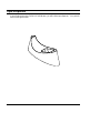
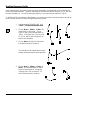
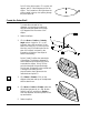
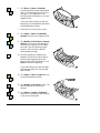
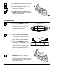
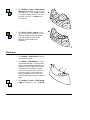
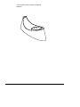
Boolean Solids Tutorial
Introduction
The CADMAX Solid Master Tutorial is a great way to learn about the benefits of constructive (boolean)
solid modeling with CADMAX. We have assembled four typical parts that you will be able to construct
using CADMAX Solid Master. Each part should take between 20-40 minutes to complete.
The tutorial assumes that you already have some familiarity with CADMAX. In you are unfamiliar
with CADMAX, review the Getting Started section first. Here are several additional suggestions before
getting started:
!
In the tutorial there are several conventions that are used with text. The text Draw > Circle >
Center Radius means to click on the Draw menu, hold the cursor over the Circle function until the
Circle sub-menu pops, then click on Center Radius.
!
When you see a statement that starts with the word “set”, this means you are to set a modifier
value in the currently displayed Function box. For example, in the Line function box, you will see
a -Connect? modifier. When you see the statement, “Set -Connect? to off”, this means you
should set it off by clicking on the word Connect if it isn’t already off.
!
Sometimes you will be asked to set a specific value for a modifier. For example, in the Circle
Function box you will see a modifier called -Radius? with a combo box below it and a history
arrow. When you see the statement, “Set -Radius? to .25”, this means you should click in the
-Radius? text field and type in the value or use the history arrow to select previous value.
!
When an instruction includes an arrow key ( 6 7 8 9) followed by a number, hold down the Ctrl
key before pressing the specified arrow. For example, <Ctrl+6>1 means hold down the Ctrl key
and press 6, then release the keys and press 1. After you type in the value, press Enter.
!
Context sensitive prompts are available for each function in the message area at the bottom of the
screen. Help is available buy pressing F1.
!
In the tutorial, we recommend when you should zoom in or out on the drawing to get better views
of your work. In addition to our recommendations, you should feel free to use the View menu to
Zoom around the drawing as you feel is appropriate. Press F10 to go to previous zooms or F11 to
make a new zoom or use the View shortcut icons on the right side of the display.
!
To load a specified drawing, press F4 to Open a drawing. The drawings that you will be asked to
open are located in the \SAMPLES sub-folder under the folder that you installed CADMAX.
CADMAX User's Manual
Boolean Solids Tutorial / 1
Tape Dispenser
In your final project using CADMAX Solid Master, you will build a tape dispenser. Your part will
look like the figure below.
2 / Boolean Solids Tutorial
CADMAX User's Manual
Draft the Dispenser Profile
Since constructing this part requires some precise point placement, we thought that color coordinating the
points would ease the process. Therefore, some steps will use both the name of the point (P1, S1, etc.) and
the color allocated to it. You will be making the majority of your part using the Attribute LTBLUE.
To build the initial cross sections of the dispenser, you are going to construct a spline through a set of given
points, and then construct an ellipse through a second set of points.
1. Load the drawing DSPNSR.DWG, click
on Edit > Surfaces and boolean solids.
2. Click on Draw > Spline > Create. Set
-Input Style? to ‘thru points’, -Curve
Type? to ‘open’ and -Attribute Name? to
‘violet’. In the front view, click on points
P1, P2, P3, and P4 (the violet points), as
shown in the illustration.
3. Click on Done in the Spline Function box
to accept the points for the spline.
The illustration to the right shows the spline
created, passing through the points specified.
4. Click on Draw > Ellipse > Center, 2
Points. Set -Attribute Name? to ‘ltblue’
and set -Ellipse Extent? to ‘full ellipse’.
In the top view, click on points P1, P2,
and P3 (the blue points), as shown.
CADMAX User's Manual
Boolean Solids Tutorial / 3
Point P1 is the ellipse center, P2 is a point at 0
degrees, and P3 is the 90 degree point of the
ellipse. The illustration to the right shows the
ellipse created in the top view passing through
the points specified.
Create the Outer Shell
To create the outer wall of the
dispenser, you are going to scale and
extrude the ellipse upward at an angle
of 15 degrees from the center of the
ellipse.
1.
Select the ellipse.
2.
Click on Draw > Surface > Scale by
Angle and set -Angle? to ‘15'. In the
isometric view, click on points P1 (the
base of the blue line), P2 (the top of the
blue line), and P3 (the blue point at the
start of the ellipse), as shown in the
illustration (only part of the ellipse is
shown intentionally) .
Points P1 and P2 define the neutral axis
of the ellipse. The distance between P1
and P2 determines the amount by which
to extrude the ellipse. Point P3 is the
point that scales at the specified angle
(in this case, 15 degrees) to the neutral axis.
The angle of all other points is
proportioned to their distance to the
neutral axis and point P3.
3.
Click Select > Element. Click on the
ellipses at the base and top of the dispenser
shell to select them.
4.
Click Draw > Surface > Simple, make sure
all surface types are set ‘on’, and -Makes
Solids? is set ‘off’ and click on Finish to
close the dispenser shell with planes on the
top and bottom.
5.
Select the spline.
4 / Boolean Solids Tutorial
CADMAX User's Manual
6.
Click Draw > Surface > Extrusion.
Extrude the spline through the dispenser
shell. Click anywhere as a pick up point
and type <Ctrl+PageDown>11 to
extrude the spline a distance of 11 in the
negative Z axis.
In the next series of steps, you will trim
away the top of the dispenser shell above
the extruded spline surface.
7.
Zoom back out to see the four views.
8.
Click Select > Select > All Attached
Surfaces and click on the dispenser shell.
9.
Click Modify > Edit Surface > Intersect
and Trim. Click on the extruded spline
surface as the cutting tool (it boundary
turns red), then click below the spline
surface in the front view to identify
which geometry to keep.
10. Once the operation is complete, the
dispenser shell will be cut at the spline
surface and the geometry above the
spline surface will be left selected. Click
Erase to remove this geometry.
In the next few steps, you will trim away
the excess geometry from the extruded
spline surface.
11. Click Select > Select > Surface and click
on the extruded spline surface.
12. Click Modify > Edit Surface > Cut. The
spline surface will be cut into two
surfaces.
13. Click Select > Unselect > SURFACE,
and click on the surface to keep as shown
in the previous illustration.
CADMAX User's Manual
Boolean Solids Tutorial / 5
14. Click Erase to remove the excess geometry.
15. The dispenser shell is complete. Click
Select > Select > All Attached Surfaces
and click on the dispenser.
16. Click Draw > Solid > Create, the click
Finish to convert the dispenser shell from a
surface model into a solid.
Create the Cavity
1.
Click on the Set Depth icon in the
Quick Snap tool bar on the right side
of the screen. In the top view, click
on the point (the topmost red point),
as shown in the illustration.
2.
Click on Draw > Circle > Center
Radius, set -Radius? to ‘4' and set
-Circle Plane? to ‘view’. In the front
view, click on point P1 (the green
point), as shown in the illustration.
3.
Click on the Set Depth icon and set
-Set Depth? from ‘view’ back to ‘free’.
Using Set Depth enabled you to
perform “2D like” construction in an
orthogonal view while freezing the
depth to the plane identified in the
top view.
4.
Select the circle just inserted.
5.
Click on Modify > Sweep > Linear,
Surfaces, set -Sweep? to ‘ends only’,
-# Steps? to ‘1', and -Make Solids? ‘on’.
Click anywhere in the drawing to choose a
pickup point and type <Ctrl+PageUp>4
as the put down point.
6 / Boolean Solids Tutorial
SET-DEPTH point
P1
CADMAX User's Manual
6.
Click Modify > Corner > Fillet/Chamfer,
Advanced, set -Radius? to ‘1' and -Type?
to ‘Fixed radius’. Click on Add, then click
on the two boundary circles of the cavity
(they will turn red). Click Done in the
Function box.
7.
Click Draw > Solid > Subtract. Click
first on the cavity solid, then click on the
dispenser shell as the solid to change.
This step creates the cavity in the
dispenser shell as shown in the
illustration.
1.
Click 3DView > Flow Lines Off and click
on the isometric view.
2.
Click Select > Select Element. Click on
the elements as shown in the illustration.
Select the three elements that define the
outside of the tape dispenser and one of
the elements on the edge of the tape
cavity. Since the tape cavity profile is a
continuous edge, it is only necessary to
identify one element. CADMAX will
automatically apply the fillet to the entire
edge.
3.
Click Modify > Corner > Fillet Selected
Edges, set -Radius? to ‘.125', click Finish.
Fillet Edges
CADMAX User's Manual
Boolean Solids Tutorial / 7
The illustration below shows the completed
dispenser.
8 / Boolean Solids Tutorial
CADMAX User's Manual


![[ol-rs-ha6]-en - Sonic Electronix](http://vs1.manualzilla.com/store/data/005843713_1-a0736ea4d1b526b61217546e349ee9ef-150x150.png)