1
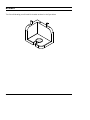
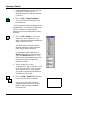
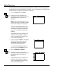
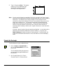
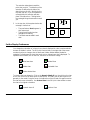
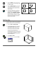
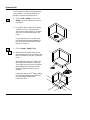
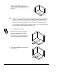
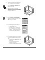
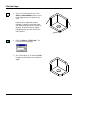
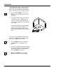
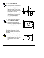
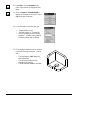
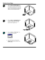
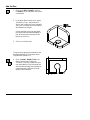
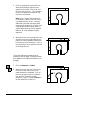
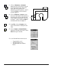
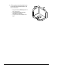
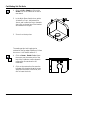
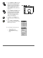
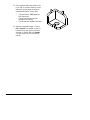
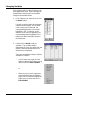
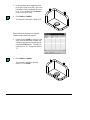
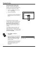
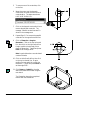
Solids Tutorial
Introduction
The CADMAX Solid Master Tutorial is a great way to learn about the benefits of feature-based
parametric solid modeling with CADMAX. We have assembled a group of typical parts that you will be
able to construct using CADMAX Solid Master. Each part should take between 20-40 minutes to
complete.
The tutorial assumes that you already have some familiarity with CADMAX. If you are unfamiliar with
CADMAX, review the Getting Started section first in CADMAX Help or in the CADMAX Users Manual.
Here are several additional suggestions before getting started:
!
In the tutorial, there are several conventions that are used with text. The text Draw > Circle >
Center Radius means to click on the Draw menu, hold the cursor over the Circle function until the
Circle sub-menu pops, then click on Center Radius.
!
Most functions are available through drop-down menus and icon tool bars. Throughout the
tutorials the written instructions tell you how to do things from the drop-down menus and the
icons to the left show you how to accomplish the same operation using icons. The first icon is the
icon to click on the main tool bar, and the second indented icon is the icon on the vertical function
bar.
< Locate this icon on the top tool bar and click on it
< Then click on this icon on the vertical tool bar that pops up on the left side
!
When you see a statement that starts with the word “set”, this means you are to set a modifier
value in the currently displayed Function box. For example, in the Line function box, you will see
a -Connect? modifier. When you see the statement, “Set -Connect? to off”, this means you
should set it off by clicking on the word Connect if it isn’t already off.
!
Sometimes you will be asked to set a specific value for a modifier. For example, in the Circle
Function box you will see a modifier called -Radius? with a combo box below it and a history
arrow. When you see the statement, “Set -Radius? to .25”, you should click in the -Radius? text
field and type in the value or use the history arrow to select previous value.
!
When an instruction includes an arrow key (6 7 8 9) followed by a number, hold down the Ctrl key
before pressing the specified arrow. For example, <Ctrl+6>1 means hold down the Ctrl key and
press 6, then release the keys and press 1. After you type in the value, press Enter.
!
Context sensitive prompts are available for each function in the message area at the bottom of the
screen. Help is available buy pressing F1.
CADMAX User's Manual
Solids Tutorial / 1
!
In the tutorial, we recommend when you should zoom in or out on the drawing to get better views
of your work. In addition to our recommendations, you should feel free to use the View menu or
the Quick View tool bar to zoom around the drawing as you feel is appropriate. Press F10 to go to
previous zooms or F11 to make a new zoom.
!
To load a specified drawing, press F4 to Open a drawing or click on File > Open. The drawings
that you will be asked to open are located in the \SAMPLES sub-folder under the folder that you
installed CADMAX.
2 / Solids Tutorial
CADMAX User's Manual
Bracket
The first solid drawing you will model is a bracket as shown in the figure below.
CADMAX User's Manual
Solids Tutorial / 3
Opening a Sketch
1.
Open the drawing FEATURE.CXS from
the /SAMPLES folder which is a
subfolder under the folder you installed
CADMAX.
2.
Click on Edit > Feature Modeling or
click on the Feature Modeling icon on
the Ribbon bar.
The first feature of the part is going to be an
extruded block. You will start by sketching a
profile of the block on a sketch plane,
dimension the block and extrude it to give it
thickness.
3.
Click on Edit > Sketch or click on the
Sketch icon on the ribbon bar. This
starts a new sketch mode and displays the
Work Plane function box.
The Work Plane function box shows
different methods to locate the sketch
plane, depth, rotation and twist.
Once the work plane is defined, the
Sketch function bar will open and place
you in the Sketch Line function. The
Sketch function bar contains many of the
functions you will use to draw and
dimension a sketch.
4.
Set the -Method? to ‘View’,
-Adjustment? to ‘None’, and click on the
front view (lower left). Now, no matter
which view you work in, as you sketch
your object, the geometry will always be
oriented to the front view.
5.
Click on Draw > Sketch Line. Working
in the front view, draft a rectangle.
As you work, notice that CADMAX
displays dynamic construction lines as
guides to help you make vertical and
horizontal lines.
4 / Solids Tutorial
CADMAX User's Manual
Adding Dimensions
Dimensions are used to make geometry the desired size. CADMAX does not require that
you add dimensions before you extrude the model. You can always return to the sketch and
add dimensions or change the sketch later in the design.
1.
Click on Dimension > Horizontal.
2.
Double-click on the top edge of the
rectangle. Drag the cursor to the desired
text position and click to place the
dimension.
Note: It may be necessary to set -Arrow
Position? to ‘inside’ or ‘outside’ to make
the dimension appear like the figures.
CADMAX automatically snaps to the
end points of the line when you doubleclick unless the midpoint is under the
cursor. Then, CADMAX snaps to the
midpoint.
Alternatively, click once on each of the
endpoints of the top edge. Drag the
cursor to the desired text position and
click to place the dimension.
3.
Type in 16 and press Enter. This assigns
a value of 16 for the dimension and
automatically resizes the rectangle
according to the assigned value.
You can always change this value at a
later time using the Equation function.
4.
Click on Dimension > Vertical.
5.
Double-click on the left edge of the
rectangle. Drag the cursor to the desired
text position and click to place the
dimension.
Alternatively, click once on each of the
endpoints of the left edge. Drag the
cursor to the desired text position and
click to place the dimension.
CADMAX User's Manual
Solids Tutorial / 5
6.
Type in 12 and press Enter. This assigns
a value of 12 for the dimension and
automatically resizes the rectangle
according to the assigned value.
Note:
Once the vertical dimension was added, CADMAX reported in the Status Area at
the bottom of the display that the sketch was well-defined with the correct number of
dimensions. This means that you have provided the correct dimensions and
constraints to fully control this sketch. Many of the constraints that are part of this
sketch were invisible to you. The lines were constrained to be parallel and the
angles were constrained to be perpendicular. These constraints were added as a
function of using the dynamic construction lines. Without those constraints, it
would have been necessary to add three 90E angular dimensions to make the sketch
well-defined.
CADMAX does not require that each sketch be well-defined. You can add only the
dimensions and constraints needed and continue modeling. You can set your
Sketch Preferences to display the status of sketch geometry. See Sketching in the
CADMAX Solid Master Users Manual for more information on colors and display
status.
Extrude the Rectangle
The first feature in a part is called the base.
1.
Click on Feature > Extrude Sketch or
click on the Extrude Sketch icon on the
top tool bar.
The Extrude Base dialog box appears so
you can specify the type and distance of
the extrusion.
2.
Set -Extrude Distance? to ‘12' and
-Extrude Extent? to ‘Distance Above’.
6 / Solids Tutorial
CADMAX User's Manual
The extrusion takes place toward the
point that you click. The direction of the
extrusion is defined by the side of the
sketch that you click on. Working in the
top view (top left), if you click above the
rectangle then the extrusion will take
place in that direction. Clicking below
the rectangle brings the extrusion toward
you.
3.
In the top view, click anywhere below the
rectangle. Notice that:
•
•
•
The new feature, Base1, appears in
the Feature tree.
The top level function bar has
changed for Modeling.
The sketch was extruded in each
view.
Set the Display Preferences
You change the orientation of a view or how a view is displayed in order to see boundaries
that are not visible in a view. The 3D Quick View tool bar on the right side of the screen
contains functions to change a view to wireframe, hidden, hidden-dashed, shaded or
unshaded. Following are the icons that permit you to change how a view is displayed. To
operate these functions, click on the icon, then click on the view to change.
Wireframe view
Shaded View
Hidden view
Unshaded View
Hidden dashed view
To rotate a view, use dynamics. Click on the Dynamic View Roll icon, then click on the view
to roll, then click on a roll about point to start the roll. Normally, the roll about point is on
geometry in the model. Drag the cursor in the direction of the roll and click again to anchor
the view at the new orientation. Use Previous View in the 3D Quick View toolbar to return
the view to its original orientation.
Dynamic view roll
CADMAX User's Manual
Previous View
Solids Tutorial / 7
1.
Click on Hidden in the 3D Quick View
tool bar, then click on the isometric view
to make it hidden.
2.
Click on Hidden-dashed in the 3D Quick
View tool bar, then click on the front,
top, and side views to make each view
hidden-dashed.
3.
If some of the geometry is outside the
view window, you can easily pan the
window. Click on Dynamic View Move in
the 3D Quick View tool bar. Click on
the view to move. Then, click on the
point to move the view about. Drag the
geometry and click again to place the
view at the new location.
Shell Three Sides
The Shell feature is used to remove specified
faces of an object and to set a wall thickness.
1.
Click on Select > Select Element.
2.
In the isometric view, click on the three
surfaces identified by the “P” in the
figure shown at right. Make sure you
click on the surface and not the edge.
P
P
P
As you click on each surface, its
boundary geometry will turn yellow and a
surface tag will be displayed. In this case,
since the selected surfaces were planes,
the surface tag is a “P”.
3.
Click Feature > Shell.
4.
Set -Thickness? to ‘2' and click Finish.
8 / Solids Tutorial
CADMAX User's Manual
Insert a Hole
The Cut feature is used to remove geometry
from the base. First, draw a sketch of the
geometry to be cut, then apply the cut.
1.
Click on Edit > Sketch or click on the
Sketch icon on the ribbon bar to start a
new sketch.
2.
In the Work Plane function box, set the
-Method? to ‘Face’, -Adjustment? to
‘None’ and in either the top or isometric
view, click on the face indicated in the
figure.
As you wave the cursor over the object,
the face that will be selected displays in
red. Make sure the bottom face is red
before you click on it.
3.
Click on Draw > Sketch Circle.
4.
Working in the isometric view, you are
going to place a circle in the center of the
face. Pay attention, this part is a little bit
tricky.
Wave the cursor over the 1st edge to get
the endpoints and midpoint to pop up.
Then, wave the cursor over the midpoint
which displays horizontal and vertical
dynamic construction lines from the
midpoint.
Repeat this step for the 2nd edge creating
the intersection between the midpoints
of the two edges using dynamic
construction lines.
CADMAX User's Manual
Solids Tutorial / 9
5.
Click on the intersection of the two
construction lines and drag the cursor out
from the center, clicking again to place
the circle.
Note:
At this time, it is only necessary to add a radial dimension to specify the radius of
the circle. The position of the circle on the object was determined by placing the
center point of the circle on the intersection of the two construction lines. No
matter how the object is modified, the circle will always be centered on the face.
If the circle was going to be located at another position on the face, the dimensions
from the edge would be required to place the circle.
6.
Click on Dimension > Radial.
7.
Wave the cursor over the circle until it
turns red and an echo of the radial
dimension is displayed. Click on the
circle, drag the cursor to locate the text,
and click to place the radial dimension.
8.
Type 2 and press Enter to set the radius
of the hole to 2.
10 / Solids Tutorial
CADMAX User's Manual
9.
Actually, the radius was supposed to be
2.2. It is easy to correct this mistake.
Click on Dimension > Equation in the
Sketch function bar.
10. Wave the cursor over the radial
dimension until it turns red. Click on the
dimension, type in 2.2 and press Enter to
change the radius to 2.2.
11. Click on Feature > Extrude Sketch to
display the Extrude function box. Select
Cut as the type of extrude.
12. In the Extrude Cut function box, set:
•
•
•
-Target Solids? to ‘All’
-Extrude Extent? to ‘Through All’
It is not necessary to set -Extrude
Distance?. Its value is only used by
‘Distance Above’ and ‘Midplane’.
13. Click anywhere inside one of the views to
cut the hole through the object. Notice
that:
•
•
•
CADMAX User's Manual
The new feature, Cut1 appears in the
Feature tree.
The top level function bar has
changed for Modeling.
The hole has been added to the base.
Solids Tutorial / 11
Fillet the Edges
1.
Zoom in on the isometric view. Click
Select > Select Element and click on the
three edges shown in the figure to the
right.
Notice that the edges and surfaces
highlight in red as you move the cursor
over them identifying which item will be
selected. Make sure only the edge is
highlighted when you click and not the
entire surface.
2.
Click on Feature > Fillet, Fixed. The
Fillet function box appears.
3.
Set -Fillet Radius? to ‘3' and click Finish
to apply the fillet feature to the selected
edges.
12 / Solids Tutorial
CADMAX User's Manual
Cut the Slot
In the next series of steps, you will cut a slot
from the hole to the edge. In the previous
sketch, the hole was drafted in the isometric
view. In this series, you will use the top view.
1.
Click on Edit > Sketch or click on the
Sketch icon on the ribbon bar to start a
new sketch.
2.
In the Work Plane function box, Set the
-Method? to ‘View’, -Adjustment? to
‘Origin’, click in the top view, then click
on one of the edges of the face indicated
in the figure.
This sets the depth of the sketch plane in
the view. All geometry added in this
sketch will be oriented to the top view
and at the depth specified by the second
point.
The next series of steps will be done in the
top view. To make it easier to work in that
view, you can Zoom up on the view.
3.
Click on Zoom in the Quick View tool
bar located on the right edge of the
display.
4.
Click on one corner of the top view, drag
the cursor diagonally across the view and
click again to zoom in on the drawing.
Click on Resume to continue.
Note: Use Previous to return to the
previous zoom window or press F10.
CADMAX User's Manual
Solids Tutorial / 13
5.
Click on Draw > Sketch Line.
6.
Wave the cursor over the center point of
the circle to have the dynamic
construction lines pop up from the center
point. Draw a rectangle using the
horizontal construction line as the top
edge of the rectangle, as shown in the
illustration. Make sure the bottom edge
is past the edge of the bracket.
By using the horizontal construction line
as a guide, the edge of the rectangle is
always constrained to the center of the
circle. If the size of the bracket is
changed, the relationship between the
hole and slot will be maintained.
7.
The slot is going to have a width of 2.2.
Click on Dimension > Horizontal.
8.
Double-click on the top edge of the
rectangle. Drag the cursor to the desired
text position and click to place the
dimension. Type 2.2, then press Enter to
set the width to 2.2.
The midpoint of the top edge of the slot will
be coincident with the center of the hole.
We’ll add a constraint to get both points to
be identical.
9.
Click on Draw > Constrain > Connect.
Wave the cursor over the top edge of the
rectangle and click on the midpoint of
the line. Then, wave the cursor over the
hole and click on the center point of the
hole to center the rectangle over the
hole.
14 / Solids Tutorial
CADMAX User's Manual
10. Press F10 or click on Previous in the
Quick View tool bar to display the four
views.
11. Click on Feature > Extrude Sketch to
display the Extrude function box. Select
Cut as the type of extrude.
12. In the Extrude Cut function box, set:
•
•
•
-Target Solids? to ‘All’
-Extrude Extent? to ‘Through All’
It is not necessary to set -Extrude
Distance?. Its value is only used by
‘Distance Above’ and ‘Midplane’.
13. Click anywhere inside one of the views to
cut the slot through the object. Notice
that:
•
•
•
CADMAX User's Manual
The new feature, Cut2, appears in
the Feature tree.
The top level function bar has
changed for Modeling.
The slot has been added to the base.
Solids Tutorial / 15
Fillet the Slot and Edges
1.
Click on Select > Select Element and
click on top surface of the bracket shown
in the figure to the right. Make sure you
click on the surface and not on any of the
edges. The surface edges will highlight in
yellow and the surface tag will show.
2.
Click on Select > Unselect Element and
click on the two inside edges of the
surface to unselect them. They will
return to their original color.
3.
Click on Feature > Fillet, Fixed. The
Fillet function box appears.
4.
Set -Fillet Radius? to ‘.25' and click
Finish to apply the fillet feature to the
selected edges.
16 / Solids Tutorial
CADMAX User's Manual
Add Set Pins
1.
Click on the Edit > Sketch or click on
the Sketch icon on the ribbon bar to start
a new sketch.
2.
In the Work Plane function box, set the
-Method? to ‘Face’, -Adjustment? to
‘None’, and in either the top or isometric
view, click on the top face of the bracket
as indicated in the figure.
As you wave the cursor over the object,
the face that will be selected displays in
red. Make sure the top surface is red
before you click on it.
3.
Zoom in on the top view.
The set pins are going to be centered on the
top edge a distance of 5 from each corner.
They will have a radius of .5.
4.
Click on Draw > Sketch Circle in the
Sketch function box. Make sure
-Connect? is checked. Wave the cursor
over the midpoint of the horizontal line
at the bottom left edge of the bracket to
create a dynamic construction line as
shown in the illustration.
Use the midpoint of this edge
CADMAX User's Manual
Solids Tutorial / 17
5.
Click on the dynamic construction line
above the fillet edge, drag the cursor
away from the center of the circle, and
click to insert the circle. This constrains
the circle to always be centered on the
top face of the bracket.
Note: Since -Connect? was checked, a
circle equal in radius to the first circle is
now attached to the cursor. Inserting
additional circles with the same radius
requires only a single click. Each circle is
constrained to have an equal radius. A
single Radius dimension will change the
radius of all circles added during this
sequence.
6.
Wave the cursor over the midpoint of the
vertical line at the top right edge of the
bracket to create a dynamic construction
line as shown in the illustration. Click on
the construction line to position a second
circle along this line.
The circles have been constrained to be
centered on the top edge. Dimensions need
to be added for the radius and distance from
the edge.
7.
Click on Dimension > Radial.
8.
Wave the cursor over one of the circles
until it turns red and an echo of the
radial dimension is displayed. Click on
the circle, drag the cursor to locate the
text, and click to place the radial
dimension. Type in .5 and press Enter to
set the radius of the holes to .5.
18 / Solids Tutorial
CADMAX User's Manual
9.
Click on Dimension > Horizontal.
Wave the cursor over the top circle and
click on the center point, click on the
upper right corner, position the
dimension, and click to place it. Type in
5 and press Enter to set the distance
from the edge to 5.
10. Click on Dimension > Vertical. Wave
the cursor over the left circle and click on
the center point, click on the lower left
corner, position the dimension, and click
to place it. Type in 5 and press Enter to
set the distance from the edge to 5.
11. Press F10 or click on Previous in the
Quick View tool bar to display the four
views.
12. Click on Feature > Extrude Sketch to
display the Extrude function box. Select
Boss as the type of extrude.
13. In the Extrude Boss function box, set:
•
•
•
CADMAX User's Manual
-Target Solids? to ‘All’
-Extrude Distance? to ‘3’
-Extrude Extent? to ‘Distance
Above’
Solids Tutorial / 19
14. Click anywhere above the object in the
front view to show the direction of the
boss. Notice that:
•
•
•
20 / Solids Tutorial
The new feature, Boss1, appears in
the Feature tree.
The top level function bar has
changed for Modeling.
The pins have been added to the
base.
CADMAX User's Manual
Cut Mating Set Pin Hole
1.
Click on Edit > Sketch or click on the
Sketch icon on the ribbon bar to start a
new sketch.
2.
In the Work Plane function box, set the
-Method? to ‘Face’, -Adjustment? to
‘None’, and in either the top or isometric
view, click on the top face of the bracket
as indicated in the figure.
3.
Zoom in on the top view.
The mating set pin hole is going to be
centered on the top edge a distance of 4 from
the corner. It will have a radius of .5.
4.
Click on Draw > Sketch Circle. Wave
the cursor over the center point of the
top circle .5 radius to create a dynamic
construction line as shown in the
illustration.
5.
Click on the construction line near the
left edge of the bracket, drag the cursor
away from the center of the circle, and
click to insert the circle.
CADMAX User's Manual
Solids Tutorial / 21
6.
Click on Dimension > Radial. Wave the
cursor over the circle until it turns red
and an echo of the radial dimension is
displayed. Click on the circle, drag the
cursor to locate the text, and click to
place the radial dimension. Type in .5
and press Enter to set the radius of the
holes to .5.
7.
Click on Dimension> Horizontal. Wave
the cursor over the circle that was just
inserted and click on the center point,
click on the upper left corner, position
the dimension, and click to place it.
Type in 4 and press Enter to set the
distance from the edge to 4.
8.
Press F10 or click on Previous in the
Quick View tool bar to display the four
views.
9.
Click on Feature > Extrude Sketch to
display the Extrude function box. Select
Cut as the type of extrude.
10. In the Extrude Cut function box, set:
•
•
•
22 / Solids Tutorial
-Target Solids? to ‘All’
-Extrude Distance? to ‘3'
-Extrude Extent? to ‘Distance
Above’
CADMAX User's Manual
11. Click anywhere below the sketch in the
front, side, or isometric views to cut the
mating pin hole through the object to
complete the bracket. Notice that:
•
•
•
The new feature, Cut3, appears in
the Feature tree.
The top level function bar has
changed for Modeling.
The slot has been added to the base.
12. Save the completed bracket. Click on
File > Save As or press F3. In the Full
Path text entry area, type in the name
‘bracket’ for the file and click Save As.
You will use this file in the Detailing
tutorial.
CADMAX User's Manual
Solids Tutorial / 23
Changing Variables
Each variable used to create the bracket can
be changed at any time. Several changes can
be applied and then the part can be rebuilt
using the new variable values.
1.
In the Feature tree, wave the cursor over
the Base1 feature.
It is easy to see the relationship between
a feature and the model. As you wave
cursor over any of the features, the
corresponding geometry in the model
highlights in red. Conversely, as you
wave the cursor over the geometry, the
corresponding feature highlights in the
feature tree and its name also shows in
the Status area.
2.
Double-click on Base1 to edit its
variables. The Variables table is
displayed and if there is a sketch that was
used to create the selected feature, its
dimensions are displayed.
There are two additional ways to edit the
variables of a feature:
•
In the Feature tree, right-click the
feature to display the Feature pop up
menu and click on Edit Variables.
or
•
24 / Solids Tutorial
Wave the cursor over the geometry
until the desired feature highlights.
Right-click the feature to display the
Feature pop up menu and click on
Edit Variables.
CADMAX User's Manual
3.
In the Variables table, change the value
for d1 from 16.000 to 20.000. Click in the
field where 16.000 is displayed, then type
in 20. It isn’t necessary to press Enter or
to type in the minor zeros.
4.
Click Feature > Rebuild.
The bracket is rebuilt with a width of 20.
Edit Variables can be used to change the
variables used to define all features.
1.
Double-click on Fillet2 (or use one of the
other methods described) to display the
Variables table with the variable used to
create the Fillet2 feature. The radius is
currently set to .25. Change the radius to
.75.
2. Click Feature > Rebuild.
The bracket is rebuilt with the fillet
radius of .75 for Fillet2.
CADMAX User's Manual
Solids Tutorial / 25
Changing Sketches
Not all changes can be made by simply
changing the variables. Sometimes the
geometry in the sketch must change too.
Instead of the slot having a straight opening,
let’s change it to narrow at a 10E angle.
1.
Right-click on Cut2. From the pop up
menu, click Edit Sketch.
2.
Zoom in on the top view.
The sketch for the slot is displayed along
with the dimension that set the width of
the slot.
Since dynamic construction lines were
originally used to construct the sketch of the
slot, each edge has been constrained to be
parallel and the corners perpendicular.
Before the 90E angle of each corner can be
changed, the parallel constraints must be
removed.
If the parallel constraints were left in the
sketch, adding an 85E angular dimension
would have no effect. The lines were already
constrained to be parallel. The sketch would
become over-constrained.
3.
Click on Draw > Constrain >
Constraints.
4.
Wave the cursor over one of the vertical
edges of the rectangle. The edge turn
red and any visible geometry that has a
constraint relationship with the edge
displays in yellow.
The status area and running coordinates
area display the number of constraints
and the type of geometry that is
highlighted.
26 / Solids Tutorial
CADMAX User's Manual
5.
To remove one of the constraints, click
on the line.
6.
Wave the cursor over the dynamic
construction line that the vertical line is
constrained to. The status area shows
LINE-LINE PARALLEL.
7.
Click on the dynamic construction line to
remove the parallel constraint. The
message “Parallel constraint erased” is
shown in the message area.
8.
Repeat Steps 3-7 to remove the parallel
constraint for the opposite vertical line.
9.
Click on Dimension > Angular
Dimension. Click on the top horizontal
line, then click on the right vertical line.
Drag to position the text and click to
place the dimension. Type 85 and press
Enter to set the angle to 85E.
Note: Angular dimensions are calculated
counterclockwise.
10. Click on the left vertical line, then click
on the top horizontal line. Drag to
position the text and click to place the
dimension. Type 85 and press Enter to
set the angle to 85E.
11. Click Feature > Rebuild to close the
sketch and rebuild the model using the
new sketch.
The illustration shows the completed
bracket with the slanted slot.
CADMAX User's Manual
Solids Tutorial / 27