1
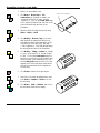
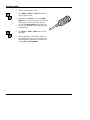
Boolean Solids Tutorial
Introduction
The CADMAX Solid Master Tutorial is a great way to learn about the benefits of constructive (boolean)
solid modeling with CADMAX. We have assembled four typical parts that you will be able to construct
using CADMAX Solid Master. Each part should take between 20-40 minutes to complete.
The tutorial assumes that you already have some familiarity with CADMAX. In you are unfamiliar
with CADMAX, review the Getting Started section first. Here are several additional suggestions before
getting started:
!
In the tutorial there are several conventions that are used with text. The text Draw > Circle >
Center Radius means to click on the Draw menu, hold the cursor over the Circle function until the
Circle sub-menu pops, then click on Center Radius.
!
When you see a statement that starts with the word “set”, this means you are to set a modifier
value in the currently displayed Function box. For example, in the Line function box, you will see
a -Connect? modifier. When you see the statement, “Set -Connect? to off”, this means you
should set it off by clicking on the word Connect if it isn’t already off.
!
Sometimes you will be asked to set a specific value for a modifier. For example, in the Circle
Function box you will see a modifier called -Radius? with a combo box below it and a history
arrow. When you see the statement, “Set -Radius? to .25”, this means you should click in the
-Radius? text field and type in the value or use the history arrow to select previous value.
!
When an instruction includes an arrow key ( 6 7 8 9) followed by a number, hold down the Ctrl
key before pressing the specified arrow. For example, <Ctrl+6>1 means hold down the Ctrl key
and press 6, then release the keys and press 1. After you type in the value, press Enter.
!
Context sensitive prompts are available for each function in the message area at the bottom of the
screen. Help is available buy pressing F1.
!
In the tutorial, we recommend when you should zoom in or out on the drawing to get better views
of your work. In addition to our recommendations, you should feel free to use the View menu to
Zoom around the drawing as you feel is appropriate. Press F10 to go to previous zooms or F11 to
make a new zoom or use the View shortcut icons on the right side of the display.
!
To load a specified drawing, press F4 to Open a drawing. The drawings that you will be asked to
open are located in the \SAMPLES sub-folder under the folder that you installed CADMAX.
CADMAX User's Manual
Boolean Solids Tutorial / 1
Connector Screw
In this section, you will use CADMAX Solid Master to build the screw for the 27-pin DIN connector that
you constructed in the previous section. By now you have started to become familiar with CADMAX’s
operation for geometry selection using Select and right clicking to select and modify geometry. The
following instructions will have more brevity. For example, instead of saying “Click Select > Select
Element, then select the line”, the instructions will read “Select the line”. You have already learned that
there are several ways you can select the line, and it will be your option to choose the best method.
Your final part should look similar to this:
2 / Boolean Solids Tutorial
CADMAX User's Manual
Draft connector screw body components
1. Open the drawing CONNECT, and click on
Edit > Surfaces and boolean solids or click on
the 3D icon on the Ribbon bar.
2. Click CPL > Align to View, and click on the
front view.
3. Click Draw > Circle > Center Radius, set
-Radius? to ‘.15', set -Circle Plane? to
‘CPL/Pnts’, set -Attribute Name? to ’visible’
and insert the circle in the top view.
4. Select the circle.
5. Click Modify > Sweep > Linear Surfaces, set
-Sweep? to ‘end only’, and set -Make Solids?
‘on’. Click anywhere as a pickup point and type
<Ctrl+PageDown>.625 as the put down point.
6. In the top view, to the left of the cylinder,
Click Draw > Arc > Center Start Angle,
set -Angle? to ‘-90', and set -Arc Plane? to
‘view’. Click anywhere as the center point of
the top arc of the profile in the illustration and
type <Ctrl+7>.03125.
7. Click Draw > Line, click on the end point of
the arc and type <Ctrl+PageUp>.375.
8. Click Draw > Arc > Center Start Angle,
set -Angle? to ‘90', type <Ctrl+6>.03125
as the center point of the arc and click on the
endpoint of the line as the arc start point.
9. Select the profile just drafted.
10. Click Modify > Sweep > Rotate Surface,
set -Continuous? ‘off’, -# Steps? to ‘3', Angle? to ‘360', -With? to ‘arcs’ and -Make
Solids? to ‘yes’. Click on the open endpoint of
one arc as the first rotate about point, and click
on the open endpoint of the opposite arc to
define the rotate about line and form a solid.
11. Click Erase to remove the original profile.
CADMAX User's Manual
Boolean Solids Tutorial / 3
Assemble connector screw body
1. Zoom in on the isometric view.
2. Click Draw > More Lines > 1 Pt
Construction, set -System? to ‘model’, set
-Construction Size? to ‘fill view’, and set
-Angle? to ‘0'. Click on the Center point snap
icon in the Quick Snap tool bar and click on the
circle of the main body as shown in the
illustration.
Snap to circle centerpoint
3. Select the small solid object to the side using
Select > Select > Solid.
4. Click Modify > Move or Copy, click on the
small object at its nearest tip as the pick up
point and put it down at the intersection of the
circle and line on the main body, then type
<Ctrl+PageDown>.10 to slide the part along
the main object as shown in the illustration.
5. Click Modify > Sweep > Rotate, set -Sweep?
to ‘none’, set -# Steps? to ‘8', and set -Angle?
to ‘360'. Click on the Center point snap icon
and click on one of the circles of the main body
as the first point of the rotate about line, click
on the Center point snap icon and click on the
opposite circle of the main body as the second
point of the rotate about line to complete the
circular array.
6. Click Erase to remove the original object.
7. Press Ctrl+A to select all editable levels, then
click Select > Unselect > Solid and click on
the main body.
8. Click Draw > Solid > Subtract, and click on
the main body as the solid to change.
4 / Boolean Solids Tutorial
CADMAX User's Manual
9. Click Modify > Corner >
Fillet/Chamfer Advanced, set -Radius?
to ‘.03125', set -Type? to ‘Fixed radius’,
click Add, then click on the two circles
indicated in the illustration, then click
Done.
10. Right click, click Erase, then click on the
construction line to erase it.
Draft connector screw
1. Zoom in on the top view.
2. Click Draw > Line, click anywhere in the
top view to start the lower point of the
profile shown in the illustration. Then at
the keyboard enter:
<Ctrl+PageDown>.5
<Ctrl+7>.03125
<Ctrl+PageDown>.0625
<Ctrl+6>.03125
<Ctrl+PageDown>.0625
<Ctrl+7>.03125
<Ctrl+PageDown>.125
3. Click Draw > More Lines > 1 Pt
Construction, set -System? to ‘view’, set
-Construction Size? to ‘fill view’, and set
-Angle? to ‘90'. Type <Ctrl+6>.0625
to place the construction line .0625 to the right
of the profile.
4. Select the profile but not the construction line.
5. Click Modify > Sweep > Rotate Surfaces,
set -Sweep? to ‘ends only’, set -Continuous?
‘on’, -# Steps? to ‘1', -Angle? to ‘360', and
-With? to arcs. Click on any two points on the
construction line as the rotate about line to
form a solid of the bottom of the screw
connector.
6. Click Erase to remove the original profile, then
click on the construction line to erase it.
CADMAX User's Manual
Boolean Solids Tutorial / 5
Final Assembly
1. Zoom in on the isometric view.
2. Click Select > Select > Solid and then click
on the connector screw.
3. Right click, click Move, click on the Center
point snap icon and click on the circle at the top
of the screw connector as the pick up point.
Click on the Center point snap icon and click
on circle at the bottom of the screw body as the
put down point.
4. Click Draw > Solid > Add and click on the
main body.
5. Save the drawing as CNTSCREW unless you
are running Test Drive in which case you can
make a temporary snapshot of your working by
clicking File > Save Snapshot.
6 / Boolean Solids Tutorial
CADMAX User's Manual