1
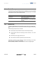
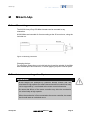
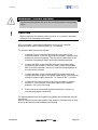
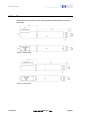
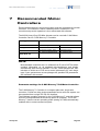
MP 77E User Manual
M-238 Heavy-Duty DC-Mike Actuator
Release: 1.0.0 Date: 02.08.2006
This document describes the
following product(s):
■
M-238.5PL
Heavy-Duty DC-Mike Actuator, Linear Encoder
■
M-238.5PG
Heavy-Duty DC-Mike Actuator, Rotary Encoder
© Physik Instrumente (PI) GmbH & Co. KG
Auf der Römerstr. 1 ⋅ 76228 Karlsruhe, Germany
Tel. +49 721 4846-0 ⋅ Fax: +49 721 4846-299
[email protected] ⋅ www.pi.ws
Physik Instrumente (PI) GmbH & Co. KG is the owner of the following company names and trademarks:
PI®, ActiveDrive™, Mercury™
The following designations are protected company names or registered trademarks of third parties:
Windows
Copyright 1999–2006 by Physik Instrumente (PI) GmbH & Co. KG, Karlsruhe, Germany.
The text, photographs and drawings in this manual enjoy copyright protection. With regard thereto, Physik
Instrumente (PI) GmbH & Co. KG reserves all rights. Use of said text, photographs and drawings is
permitted only in part and only upon citation of the source.
First printing 02.08.2006
Document Number MP 77E BSc, Release 1.0.0
M-238_User_MP77E.doc
Subject to change without notice. This manual is superseded by any new release. The newest release is
available for download at www.pi.ws (http://www.pi.ws).
About this Document
Users of this Manual
This manual is designed to help the reader to install and operate the M-238 Heavy-Duty DC-Mike
Actuator. It assumes that the reader has a fundamental understanding of basic servo systems, as well as
motion control concepts and applicable safety procedures.
The manual describes the physical specifications and dimensions of the M-238 Heavy-Duty DC-Mike
Actuator as well as the procedures which are required to put the associated motion system into operation.
Conventions
The notes and symbols used in this manual have the following meanings:
WARNING
Calls attention to a procedure, practice or condition which, if not
correctly performed or adhered to, could result in injury or death.
!
CAUTION
Calls attention to a procedure, practice, or condition which, if not
correctly performed or adhered to, could result in damage to equipment.
NOTE
Provides additional information or application hints.
The motion controller and the software tools which might be mentioned within this documentation are
described in their own manuals. All documents are available on the respective product CD. Current
releases can be downloaded from the PI Website as PDF files (www.pi.ws (http://www.pi.ws)), obtained
from your Physik Instrumente sales engineer or from [email protected] (mailto:[email protected]).
Contents
1
Introduction
1.1
1.2
1.3
1.4
1.5
2
3
12
PWM Amplifiers................................................................................. 12
Limit Switches ................................................................................... 12
Reference Switch .............................................................................. 13
Rotary Encoder (M-238.5PG) ........................................................... 13
Linear-Scale Position Encoder (M-238.5PL)..................................... 13
Motor Controllers............................................................................... 13
Host PC............................................................................................. 14
Troubleshooting
4.1
4.2
9
Mounting ............................................................................................. 9
Interconnecting the System................................................................. 9
Operational Considerations
3.1
3.2
3.3
3.4
3.5
3.6
3.7
4
Product Description............................................................................. 3
Prescribed Use.................................................................................... 6
Safety Precautions .............................................................................. 7
Model Survey ...................................................................................... 8
Unpacking ........................................................................................... 8
Start-Up
2.1
2.2
3
15
Diagnosis .......................................................................................... 15
Customer Service.............................................................................. 17
5
Maintenance
18
6
Technical Data
19
6.1
6.2
6.3
6.4
7
Specifications .................................................................................... 19
Range and Transmission Ratio Values............................................. 20
Dimensions ....................................................................................... 21
Connector Pin Assignments.............................................................. 23
Recommended Motor Controllers
25
8
Glossary of Terms
27
9
Index
31
Introduction
1
Introduction
1.1
Product Description
Figure 1: M-238.5PL Heavy-Duty Mike actuator (with CD for size comparison)
www.pi.ws
■
High Load Capacity to 400 N
■
Optional 0.1 µm Direct-Metrology Linear Encoder for Exceptional
Precision
■
Travel Range 50 mm
■
Resolution to 0.1 µm
■
Max. Velocity 30 mm/s
■
Preloaded Frictionless Ball Screw
■
MTBF> 20,000 h
■
Vacuum-Compatible Versions Available for 10-6 hPa
M-238 MP 77E Release 1.0.0
Page 3
Introduction
The M-238 is a high-load, high-precision actuator providing linear motion up
to 50 mm, a load capacity to 400 N and high velocity to 30 mm/s. It consists
of a low-friction, heavy-duty ballscrew, driven by a closed-loop,
ActiveDrive™ DC motor with gearbox. An optional linear encoder provides
exceptional accuracy and repeatability.
Direct Metrology Linear Encoder to Compensate Mechanical
Play
The M-238.5PL model is equipped with a non-contact, optical, linear encoder
(direct metrology) with an output resolution of 0.1 µm. Because the encoder
measures the actual position of the non-rotating actuator tip, drive-train
errors like backlash and elastic deformations are eliminated. A lower-cost
version with a rotary encoder is available as model number M-238.5PG.
ActiveDrive™ DC Motor
DC motor drives offer several advantages, such as high dynamics, high
torque at low rotational speed, low heat and low vibration.
The ActiveDrive™ design, developed by PI, features a high-efficiency PWM
(pulse width modulation) servo-amplifier mounted side-by-side with the DC
motor and offers several advantages:
■
Increased efficiency, by eliminating power losses between the
amplifier and motor
■
Reduced cost of ownership and improved reliability, because no
external driver is required
■
Elimination of PWM amplifier noise radiation, by mounting the
amplifier and motor together in a single, electrically shielded case
Non-Rotating Tip
Compared to conventional rotating-tip micrometer drives, the non-rotating-tip
design offers several advantages:
www.pi.ws
■
Elimination of torque-induced positioning errors
■
Elimination of sinusoidal motion errors
M-238 MP 77E Release 1.0.0
Page 4
Introduction
■
Elimination of wear at the contact point
■
Elimination of tip-angle dependent wobble.
The lateral guiding of the tip withstands lateral forces of up to 100 N.
Ballscrews for High Speed, Precision and Lifetime
The precision-ground ballscrew is maintenance-free and preloaded to
eliminate mechanical play. Its significantly reduced friction, compared to
conventional leadscrews, allows for higher velocity, lower power
consumption and longer lifetime. The M-238 is therefore well suited for high
duty-cycle operation in industrial environments.
Limit and Reference Switches
For the protection of your equipment, non-contact Hall-effect limit and
reference switches are installed. The direction-sensing reference switch
supports advanced automation applications with high precision.
Notes
Please note, that in this manual the following product names are used
synonymously: DC-Mike, positioner, linear actuator.
www.pi.ws
M-238 MP 77E Release 1.0.0
Page 5
Introduction
1.2
Prescribed Use
Correct operation of the M-238 Mikes is only possible in combination with a
suitable controller/driver (ordered separately) and software.
To ensure proper performance of the servo-control system,, the controlling
device must be able to read out and process the signals from reference and
limit switches and the incremental position encoder.
Based on their design and realization, the M-238 Mikes are intended for
single-axis positioning, adjusting and shifting of loads at various velocities.
M-238 Mikes can be mounted in any orientation. To achieve the specified
guiding accuracy, the Mikes have to be mounted according to the load
specifications given in the technical data tables.
The Mikes may only be used for applications suitable according to the device
specifications.
Respect the safety instructions given in this User Manual. The user is
responsible for the correct installation and operation of the M-238.
The verification of the technical specifications by the manufacturer does not
imply the validation of complete applications. In fact the user is responsible
for the process validation and the appropriate releases.
The M-238 is a laboratory apparatus as defined by DIN EN 61010. It meets
the following minimum specifications for safe operation (any more stringent
specifications in the technical data table are, of course, also met):
www.pi.ws
■
Indoor use only
■
Altitude up to 2000 m
■
Temperature range 5°C to 40°C
■
Max. relative humidity 80% for temperatures up to 31°C, decreasing
linearly to 50% relative humidity at 40°C
■
Line voltage fluctuations not greater than ±10% of the line voltage
■
Transient overvoltages as typical for public power supply
Note: The nominal level of the transient overvoltage is the standing
surge voltage according to the overvoltage category II (IEC
60364-4-443).
■
Degree of pollution: 2
M-238 MP 77E Release 1.0.0
Page 6
Introduction
1.3
Safety Precautions
Read carefully the User Manuals of all other components involved such as
controllers or software.
Read the following before operating the equipment covered in this manual:
CAUTION
Read this before operating the equipment covered in this manual.
Always keep the User Manual safe and close to the described device. In
case of loss or or damage to the instructions, please order a new copy
from your PI distributor. Also keep and add all further information (e.g.
extended instructions or Technical Notes) to the User Manual.
!
WARNING—CRUSH HAZARD
Never put anything where the tip or any connected object could possibly
trap it.
WARNING
M-238 stages are powered by powerful electric motors and can
accelerate to high speeds. Be aware that automatic limit switch halt may
not be supported by, or activated at the motor control electronics.
Be aware that failure of the motor controller may drive the mechanics
into a hard stop at high speeds.
When the mechanics is first connected to the motor controller, be aware
that it could start an undesired move.
CAUTION
!
Do not let the mike run into the hard stop
Due to the high power of the motor and the high speed that can be
achieved, crashing can damage the gear head and / or the whole
actuator.
www.pi.ws
M-238 MP 77E Release 1.0.0
Page 7
Introduction
1.4
Model Survey
The M-238 Heavy-Duty DC-Mike Actuator is available in 2 versions that differ
only in terms of the position encoder as listed in the table below. For further
specifications see the Technical Data section.
Model
M-238.5PG
M-238.5PL
1.5
Description
Heavy-Duty DC-Mike Actuator, 400 N,
50 mm, ActiveDrive™
Heavy-Duty DC-Mike Actuator, 400 N,
50 mm, ActiveDrive™, Direct-Metrology
Encoder
Unpacking
Unpack the M-238 Heavy-Duty DC-Mike Actuator with care. Compare the
contents against the items covered by the contract and against the packing
list.
The following components are included:
■
M-238 Heavy-Duty DC-Mike Actuator with ball tip and flat tip
■
C-815.38 motor cable for connecting to motor controller, 3 m, sub-D
15 pin (m/f)
■
M-500.PS power supply with line cord
■
User manual for M-238 in printed form (this document)
Inspect the contents for signs of damage. If parts are missing or you notice
signs of damage, contact PI immediately.
Save all packing materials in case the product need be shipped again.
www.pi.ws
M-238 MP 77E Release 1.0.0
Page 8
Start-Up
2
Start-Up
2.1
Mounting
The M-238 Heavy-Duty DC-Mike Actuator can be mounted in any
orientation.
M-238 Mikes are intended for front mounting at the 35-mm sleeve, using the
included nut.
Figure 2: Mounting instruction
Changing the tips:
For mounting, please be sure to hold both the tip and the spindle of the Mike
with suitable open-end wrenches, to avoid applying torque to internal parts.
2.2
Interconnecting the System
WARNING
M-238 stages are powered by powerful electric motors and can
accelerate to high speeds. Be aware that automatic limit switch halt may
not be supported by, or activated at the motor control electronics.
Be aware that failure of the motor controller may drive the mechanics
into a hard stop at high speeds.
When the mechanics is first connected to the motor controller, be aware
that it could start an undesired move.
www.pi.ws
M-238 MP 77E Release 1.0.0
Page 9
Start-Up
WARNING—CRUSH HAZARD
Never put anything where the tip or any connected object could possibly
trap it.
!
CAUTION
Before operating the device make sure that it is correctly mounted /
fastened to the operating environment.
Prior to operation, read the documentation for the motor controller.
Read the section about PWM amplifiers (p. 12) carefully.
To operate a Mike, proceed as follows:
1
Install/connect the controller following the instructions in the
controller manual. If you are using a host computer, install the host
software in the host computer. The procedure is described in the
controller User Manual and/or associated software manuals.
2
Connect the Mike to the controller using the connecting cable
(included as part number C-815.38), which comes with the Mike.
With multi-axis controllers, be sure to note the axis designation of
the connection selected.
3
Connect the Mike to the included M-500.PS power supply and
connect the power supply to line power (wide range). To activate the
M-500.PS power supply switch the "-/o"-rocker to the "-" position.
4
Command a few test moves to make sure th system is working
properly. If your controller comes with graphic user-interface
software, use it for such testing.
5
Extend the tip by commanding positive directions, retract it by
commanding negative directions.
For optimal performance and system compatiblity we recommend using PI
controllers.
Most PI controllers come with graphic user-interface software which is easy
to set up and allows quick installation and testing.
www.pi.ws
M-238 MP 77E Release 1.0.0
Page 10
Start-Up
NOTE
Most standard controllers and / or software from PI use a DAT file which
contains information on all standard micropositioners and installs
automatically with the host software. This file, called pistages.dat, also
includes an initial set of PID servo-control parameters for each stage
type. If your system does not use pistages.dat, possible PID parameters
are included in this manual.
www.pi.ws
M-238 MP 77E Release 1.0.0
Page 11
Operational Considerations
3
Operational Considerations
3.1
PWM Amplifiers
The M-238 Heavy-Duty DC-Mike Actuator feature a DC servo-motor with a
high-efficiency PWM amplifier mounted side by side. This ActiveDrive™
system provides maximum dynamic performance. An external plug-in power
supply (M-500.PS) is provided to supply the built-in amplifier. This
architecture allows high torque and high velocities while loading the motor
controller with control signals only.
3.2
Limit Switches
All M-238 positioners are equipped with non-contact, Hall-effect limit
switches (with TTL drivers).
Each limit switch sends an overtravel signal on its own dedicated line to the
controller. It is the controller that is then responsible for stopping the motion.
If it does not do so in time, the positioner will run into the hard stop.
Limit switch outputs are active-high.
!
CAUTION
Crashes can cause irreparable damage. Do not disable limit switches in
software. Test limit switch operation at low speeds. Stop system if
necessary. Do not let it run against a hard stop.
Limit Switch Specifications:
www.pi.ws
Type:
Magnetic (Hall-effect) sensors
Supply voltage
+5 V / GND, supplied by the motor controller through the motor
connector.
Signal output:
TTL level
Sink / source capab.
20 mA at 18°C
Signal logic:
Active-high; normal motor operation: low, limit sensor reached: high
M-238 MP 77E Release 1.0.0
Page 12
Operational Considerations
3.3
Reference Switch
The M-238 Heavy-Duty DC-Mike Actuator equipped with a direction-sensing
Hall-effect reference switch, which is located at about the midpoint of the
travel range. This sensor provides a TTL signal indicating whether the
positioner is to the positive or negative side of a fixed point. The rising or
falling edge of this signal can be used to indicate a known reference position
within 0.5 µm accuracy (depending on the controller). The difference in the
reference point when approached from the positive or the negative side is
about 0.2 mm to 0.4 mm. See the controller User Manual and/or associated
software manuals for the commands which make use of the reference signal.
3.4
Rotary Encoder (M-238.5PG)
The M-238.5PG is equipped with a DC-motor with a shaft-mounted position
encoder. It provides highly accurate signals whenever the position changes
by a known, small amount. By monitoring the encoder pulses, called counts,
the controller can keep track of the relative motion of the stage. To discover
the absolute position, it is necessary to drive the stage to a limit or reference
switch. Most controllers have commands to automate this procedure, which
is called referencing.
3.5
Linear-Scale Position Encoder (M-238.5PL)
An optical linear encoder is mounted in the M-238.5PL Heavy-Duty DC-Mike
Actuator featuring 0.1 µm linear resolution.
Optical linear encoders measure the actual position directly, thus eliminating
drivetrain errors such as non-linearity, backlash and elastic deformations.
3.6
Motor Controllers
M-238-series micropositioners can be connected to the same motor
controllers as other micropositioners from PI.
DC motor controllers from PI can control both analog and ActiveDrive™
(PWM) motor versions. The required operating mode is set
automatically—depending on the controller model, either directly when the
controller is powered up, or when the user chooses the connected positioner
type in the control software.
If networking several positioners, you have to keep in mind that stepper
motor devices can only be networked with other stepper-motor devices.
This manual includes a list of suitable controllers.
www.pi.ws
M-238 MP 77E Release 1.0.0
Page 13
Operational Considerations
3.7
Host PC
Most controllers from PI are in turn controlled by a host PC provided by the
user.
The controller is either installed directly in the PC (e.g. C-843 PCI board) or
connected to it over a communications interface. See the controller User
Manual for details.
PI provides software and/or drivers that run on the host PC to control the
system. Typically, there will be a control program with a graphic user
interface for testing and simple operation, and, in addition, DLL, COM and/or
LabView drivers for users who wish to use custom software. If the controller
is a PC ISA or PCI card, there will also be hardware drivers to install. See the
controller user and software manuals for installation details.
www.pi.ws
M-238 MP 77E Release 1.0.0
Page 14
Troubleshooting
4
Troubleshooting
4.1
Diagnosis
Positioner does not move.
Cables not connected properly:
■ Check the connecting cables.
Check if power supply is connected:
■ Verify that the included MS-500.PS power supply is connected and
turned on.
Mechanics has passed limit switch (is outside of allowable travel range):
■ Disconnect the device and try to move it manually. If this is not
possible please call your local distributor.
Positioner or positioner cable is defective:
■ Replace positioner with a working positioner of the same type to test a
new combination of controller and positioner (positioners of a different
type may malfunction due to unsuitable parameter settings on the
controller).
Test cable and / or replace with a working cable of the syme type.
Wrong command or wrong syntax:
■ Check the error code (with PI-GCS command set, use ERR?; see
controller and software manuals for the error code explanations).
Positioner is not referenced:
■ In the GCS command set, some closed-loop motion commands are
not executed if the mechanics has not been referenced—(ERR?
replies "5", see controller and software manuals). Reference the axis
as described in the controller and user manuals.
Wrong axis commanded:
■ Check if commanded axis is that of the desired positioner.
www.pi.ws
M-238 MP 77E Release 1.0.0
Page 15
Troubleshooting
Incorrect configuration:
■ Check for anomolous parameter settings on the controller.
Positioner does not reach position with expected accuracy.
Motion parameters are not optimized:
■ Adjust the motion parameters according to the values given in this
document.
Positioner runs jerkily and not smooth enough.
Motion parameters are not optimized:
■ Adjust the motion parameters according to the values listed in this
document.
Positioner did not stop in time and ran into a hard stop.
The controller did not stop the positioner in time:
■ Too high velocity. See also chapter "Limit Switches".
■
www.pi.ws
Turn off the motor. If possible, you may push the positioner out of the
end zone manually.
M-238 MP 77E Release 1.0.0
Page 16
Troubleshooting
4.2
Customer Service
Still having problems? Call your local distributor or write to [email protected];
please have the following information about your system ready:
www.pi.ws
■
Product codes and serial numbers of all products in the system
■
Current firmware version of the controller
■
Software version of drivers and / or host software
■
Operating system on host PC
M-238 MP 77E Release 1.0.0
Page 17
Maintenance
5
Maintenance
The actuator is designed for protection class IP4x. When operated in this
environment, no maintenance is required. If the actuator must be operated in
extremely dusty or humid environments, we recommend to contact your PI
sales engineer.
www.pi.ws
M-238 MP 77E Release 1.0.0
Page 18
Technical Data
6
Technical Data
6.1
Specifications
Models
M-238.5PG
M-238.5PL
Unit
Tolerance
Active axes
X
X
Travel range
Integrated sensor
50
Rotary Encoder
50
Linear Encoder
Sensor resolution
4000 cts/rev
0.1µm
Design resolution
0.13
0.1
µm
typ.
Min. incremental
motion
Backlash
0.5
0.3
µm
typ.
3
1
µm
typ.
Unidirectional
repeatability
1
0.3
µm
typ.
Max. velocity
30
30
mm/s
Origin repeatability
1
1
µm
Spindle pitch
2
2
mm/rev
Gear ratio
3.71:1
3.71:1
Push/pull force
400
400
N
max.
Lateral force
100
100
N
max.
Motor type
DC-motor,
ActiveDrive™
DC-motor,
ActiveDrive™
Operating voltage
24 (PWM)
24 (PWM)
V
Electrical power
80
80
W
Motion and
Positioning
mm
±20%
Mechanical
Properties
Drive properties
www.pi.ws
M-238 MP 77E Release 1.0.0
nominal
Page 19
Technical Data
Miscellaneous
6.2
Operating temperature -10 to 50
range
-10 to 50
°C
Material
Al (anodized), steel
Al (anodized), steel
Weight
2.4
2.4
kg
±5%
Cable length
3
3
m
±10 mm
Connector
Sub-D 15m
Sub-D 15m
Recommended
Controller
C-862, C-843
C-862, C-843
Range and Transmission Ratio Values
www.pi.ws
M-238.5PL
Range [mm]
50
Range [cts]
500,000
Transmission Ratio
10 cts/µm
M-238.5PG
50
371428
7.4285714 cts/µm
M-238 MP 77E Release 1.0.0
Page 20
Technical Data
6.3
Dimensions
All dimensions are given in mm, decimal places separated by commas in
drawings.
Figure 3: M-238.5PG
Figure 4: M-238.5PL
www.pi.ws
M-238 MP 77E Release 1.0.0
Page 21
Technical Data
Figure 5: Flat tip
Figure 6: Ball tip
www.pi.ws
M-238 MP 77E Release 1.0.0
Page 22
Technical Data
6.4
Connector Pin Assignments
Connector J2 (Controller Connection)
Connector type on positioner: D-Sub15m
Pin#
Signal
Direction
Function
1
ENABLE
input
Enable signal for power amplifier and motor
brake, (+5 V to +12 V)
9
2
10
3
11
4
12
5
13
6
14
7
15
8
www.pi.ws
n.c.
n.c.
PGND
MAGN
SIGN
+5V
NLIM
PLIM
REFS
GND
A(+)
A(-)
B(+)
B(-)
input
input
input
input
output
output
output
output
output
output
output
Not connected
Not connected
Ground (Power)
PWM signal magnitude (speed)
PWM signal sign (direction)
+5 V input for encoder and logic
Negative limit signal (active high), TTL
Positive limit signal (active high), TTL
Position reference signal, TTL
Ground (logic)
Encoder signal A, TTL
Encoder signal A-dash, TTL
Encoder signal B, TTL
Encoder signal B-dash, TTL
M-238 MP 77E Release 1.0.0
Page 23
Technical Data
Connector J1 (Power Supply)
Figure 7: 3-pin power supply connector
Type: 3-pin, round socket
www.pi.ws
Pin
Function
1
GND (power)
2
Voltage input (+24 V ±3 V)
3
n.c.
M-238 MP 77E Release 1.0.0
Page 24
Recommended Motor Controllers
7
Recommended Motor
Controllers
Each motorized device in the motion system must be connected to a motion
controller. The controller is either networked with or installed in a PC:
controller setup and/or operation is thus effectuated with software.
The M-238 Heavy-Duty DC-Mike Actuator can be used with C-843 Motor
Controller Card or C-862 Mercury™ Controller.
Drive type
DC Motor
Controller
Axes per controller
C-862 Mercury™
1
RS-232 bus or daisy chain
Host PC interface
Multiple controllers on yes, same or separate ports
same host PC
C-843 motor controller card
2 or 4
Internal (PCI bus)
yes, separate slots
NOTE
Most standard controllers and / or software from PI use a DAT file which
contains information on all standard micropositioners and installs
automatically with the host software. This file, called pistages.dat, also
includes an initial set of PID servo-control parameters for each stage
type. If your system does not use pistages.dat, possible PID parameters
are included in this manual.
Parameter settings for C-862 Mercury™ DC-Motor Controller
The C-862 Mercury™ Controller is a compact palm-size, single-axis
controller. C-862s are daisy-chain networkable and a multi-axis system can
be controlled from a single PC RS-232 interface.
The Windows operating program for the C-862 Mercury™ controller allows
choice of micropositioners as a start-up option for operation. The C-862
Mercury™ has the correct operating mode (analog or PWM) automatically
enabled with no extra command required.
www.pi.ws
M-238 MP 77E Release 1.0.0
Page 25
Recommended Motor Controllers
Appropriate PID Parameters for M-238.5PL
Parameter
p-term
i-term
d-term
i-limit
Recommended
Value
80
50
100
2,000
Minimum Value Maximum Value
30
0
0
0
100
80
300
2,000
velocity [cts/s]
velocity [mm/s]
acceleration [cts/s²]
acceleration [mm/s²]
300,000
30
1,500,000
150
0
0
10,000
1
300,000
30
3,000,000
300
Appropriate PID Parameters for M-238.5PG
Parameter
www.pi.ws
p-term
i-term
d-term
i-limit
Recommended
Value
180
40
250
2,000
Minimum Value Maximum Value
60
0
0
0
250
80
350
2,000
velocity [cts/s]
velocity [mm/s]
acceleration [cts/s²]
acceleration [mm/s²]
222,000
30
1,100,000
150
0
0
10,000
1
222,000
30
2,200,000
300
M-238 MP 77E Release 1.0.0
Page 26
8
Glossary of Terms
ActiveDrive™ DC Motor
Some of the advantages of DC-motor drives are good dynamic performance,
fast response, high torque at low rpm, low heat dissipation and low vibration.
The cost of a high-performance amplifier, however, is generally higher than
that for a stepper motor.
The ActiveDrive™ system reduces this cost considerably, by integrating a
PWM (pulse width modulation) driver and amplifier in the motor case. This
design provides several advantages:
■
Increased efficiency, by eliminating power losses between the
amplifier and motor
■
Reduced cost, more-compact system, and improved reliability,
because no external driver and cabling are required
■
Elimination of PWM amplifier noise radiation by mounting the amplifier
and motor together in a single electrically shielded case
Positioning accuracy is assured with either rotary or optical linear encoders.
Backlash
Position error that appears upon reversing direction. Backlash is caused by
play in the drive train components coming after the encoder, such as
gearheads or bearings, and by friction in the guiding system. Unlike
hysteresis, it can lead to instability in closed-loop setups because it causes a
deadband in the servo-loop. Some manufacturers promote controllers with
automatic backlash compensation that add the estimated amount of lost
motion upon each reversal. This solution is very limited in practice, as
backlash is not constant but varies with temperature, deceleration,
acceleration, load, leadscrew position, direction, wear, etc.
Bidirectional Repeatability
The accuracy of returning to a position from any position, regardless of
direction. Effects such as hysteresis and backlash affect bidirectional
repeatability. See also "Unidirectional Repeatability".
DC Servo-Motor
A direct-current motor that is operated in a closed-loop system (servo-loop).
Characteristics of DC servo-motors are lack of vibration, smooth running,
wide speed range and very good low-speed torque. For optimum
performance, a good motor controller with PID (proportional, integral,
derivative) algorithm and filter settings is mandatory.
Design Resolution
The theoretical minimum movement that can be made. This is a calculated
value based on the drive components (drive screw pitch, gear ratio, motor
angular resolution etc.) and does not account for nonlinearities like friction,
backlash, etc. Design resolution must not be confused with minimum
incremental motion. In systems with high gear ratios or microstepping
motors, the design resolution can be in the subnanometer range. In practice,
incremental motion of less than 0.1 µm is prevented by guiding system
friction (except with air bearings and flexures).
Maximum Push/Pull Force
Active and passive force limit in operating direction, at center of stage. Some
stages may be able to generate higher forces at the cost of reduced lifetime.
Minimum Incremental Motion
The minimum motion that can be repeatedly executed for a given input,
which is sometimes referred to as practical or operational resolution. Design
resolution and practical resolution must be distinguished. Design resolutions
of 1 nm or better can be achieved with many motor, gearbox and leadscrew
combinations. In practical applications, however, stiction/friction, windup,
and elastic deformation limit resolution to fractions of a micron. Minimum
incremental motion must be determined by actual measurements.
Repeatable nanometer or sub-nanometer resolution can be provided by
solid-state actuators (PZTs) and PZT flexure stages (see the "PZT Flexure
NanoPositioners" and "PZT Actuators" sections of the PI Catalog for details)
such as those integrated in PI's M-511.HD and M-714 Hybrid Drive stages.
Pulse Width Modulation (PWM)
The PWM mode is a highly effective method of transmitting electrical energy
at a variable rate by varying the width of pulses in a train rather than the
amplitude of an analog signal.
Unidirectional Repeatability
The accuracy of returning to a given position from the same direction.
Because unidirectional repeatability is almost unaffected by backlash and
hysteresis, it is often considerably better than bidirectional repeatability.
9
Index
A
ActiveDrive™ DC Motor • 27
P
Prescribed Use • 6
Product Description • 3
Pulse Width Modulation (PWM) • 28
PWM Amplifiers • 10, 12
R
Backlash • 27
Bidirectional Repeatability • 27
Range and Transmission Ratio Values •
20
Recommended Motor Controllers • 25
Reference Switch • 13
Rotary Encoder (M-238.5PG) • 13
C
S
Connector Pin Assignments • 23
Customer Service • 17
Safety Precautions • 7
Specifications • 19
Start-Up • 9
B
D
DC Servo-Motor • 28
Design Resolution • 28
Diagnosis • 15
Dimensions • 21
H
Host PC • 14
I
Interconnecting the System • 9
Introduction • 3
L
Limit Switches • 12
Linear-Scale Position Encoder
(M-238.5PL) • 13
M
Maintenance • 18
Maximum Push/Pull Force • 28
Minimum Incremental Motion • 28
Model Survey • 8
Motor Controllers • 13
Mounting • 9
O
Operational Considerations • 12
T
Technical Data • 19
Troubleshooting • 15
U
Unidirectional Repeatability • 29
Unpacking • 8


![Final Report - [Almost] Daily Photos](http://vs1.manualzilla.com/store/data/005658230_1-ad9be13b69bd4f2e15f58148160b0f22-150x150.png)