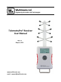
1
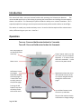
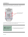
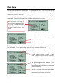
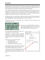
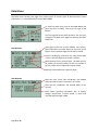
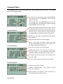
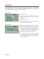
TelemetryPro® Receiver
User Manual
Rev 2.0
May 10, 2015
www.multitronix.com
email: [email protected]
Limitation of Liability
Multitronix LLC has exercised reasonable care in the design and manufacture of this product. Each one
is carefully tested prior to shipment. However, the use or application of this product is beyond the
control of Multitronix LLC and due to the nature of electronic devices, and the applications and
environments applied to them, the possibility of failure or malfunction cannot be completely eliminated.
Therefore, the buyer assumes all responsibility and uses this product at their own risk. By using this
product the user agrees to indemnify and hold harmless Multitronix LLC and its officers, agents and
assigns from any and all liability, losses, damages, costs, claims, judgments, actions, and demands arising
out of the use of this product, claimed on account of, or in any way predicated upon loss or damage to
property, or injuries to or the death of any and all persons. If you do not agree with this limitation of
liability then do not use this product.
Revision History
Rev
1.0
1.1
1.2
1.3
1.4
2.0
Date
June 9, 2014
June 26, 2014
June 28, 2014
Dec 3, 2014
Dec 9, 2014
May 10, 2015
Description
Initial Release
Added “hint” to always point antenna at rocket. Other minor updates.
Minor cleanup.
Added page about establishing a link. Added registered trademark.
Added page describing three digit transmitter ID codes.
Major update. Now includes all functionality in firmware v2.0.0.
The information in this document is subject to change without notice. For the most recent version of
this document visit: www.multitronix.com
Multitronix LLC reserves the right to change, improve or obsolete its products without prior notice.
TelemetryPro® is a registered trademark of Multitronix LLC
Copyright © 2015
Multitronix LLC
All Rights Reserved
Page 2 of 30
Introduction
This manual will help a new user become familiar with operating the TelemetryPro Receiver.
The
recommended approach is to follow along by pressing the same buttons and viewing the same displays
shown in this manual. The TelemetryPro system includes the ability to run a launch simulation. This is
especially helpful for learning to use the system and to become proficient with it before an actual flight.
The receiver is actually very intuitive and easy to use. Do not be afraid to explore all the various menus
and try different things on your own. Have fun!
Operation
Turn-on: Press and hold center button for 2 seconds.
Turn-off: Press and hold center button for 6 seconds.
Each menu page has
an identifying name
at the top.
Menu cursor
Left button is used
to navigate
backwards through
the menu pages. It
is most often used
to simply return to
the previous page.
Pressing the left
button many times
will always return
to the main menu.
Center button works just like
the “enter” key on a computer
keyboard. It is used to enter
data and commands. It also
serves as the power switch.
Right button selects the menu
item pointed to by the cursor.
It is used to navigate forward
through the various menu
pages.
Up and down buttons move
the cursor up and down.
They are also used to increase
or decrease or change settings.
Page 3 of 30
Install Batteries
Install four Duracell or other equivalent high quality AA alkaline batteries. Carefully insert batteries as
per polarity markings inside the compartment. To turn the receiver on, press and hold the center
button for two seconds. To turn it off, press and hold the center button for six seconds.
Loosen two screws to remove
battery compartment door.
It is a good idea to remove the batteries if the unit is going to be stored and unused for more than six
months. This can help avoid damage from batteries leaking electrolyte.
This screen will be shown when the receiver is first turned
on. Press any button to proceed to the main menu.
Page 4 of 30
Main Menu
The main menu operates like a “home page”. It is a good place to start. If you ever get lost the best
way to get back to a known place is to press the back button (left arrow button) many times. This will
always return you to the main menu.
The main menu has five options that can be selected: LAUNCH, RECOVER, TELEMETRY, DATA and
COMMANDS. These will all be explained in more detail throughout this user manual.
Move the menu cursor using the
up and down arrow buttons until it
is pointing to the desired option.
Then press the right arrow button
(or center button) to select that
option.
The main menu shows the estimated remaining battery life.
Transmitter battery status
Receiver battery status
Hint: To remember which battery icon is which, just remember the one on the top is the one that
flies in the rocket. The one on the bottom is for the receiver that stays on the ground.
A signal strength indicator is shown on every
screen. Maximum signal strength is “five bars”
as is shown here.
The signal strength indicator will blink “LOS”
indicating “Loss of Signal” when the link with the
transmitter has been completely lost or has not
yet been established.
“No Link” will also be shown here instead of the
transmitter battery status when there is no data
link between the transmitter and receiver.
Page 5 of 30
Establishing a Radio Link
Go to the MAIN MENU and position the cursor with the
up/down buttons until it is pointing to LAUNCH as is
shown here. Then press the right arrow button to see a
launch status menu.
Position the cursor to point to RADIO LINK and then
press the right arrow button to see the RADIO STATUS
screen.
With the cursor pointing to TRANSMITTER ID, press the
right arrow button to activate edit mode for entering
your transmitter ID code. The ID code is a three digit
number that is listed on the front of the transmitter.
Transmitters will also beep their ID codes at periodic
intervals to make it easy to determine the code even if it
has already been installed in a rocket.
Edit bars will now be blinking above and below a digit in
the ID code number. They indicate which digit will be
changed by pressing the up or down arrow buttons.
The edit bars can be moved right or left by pressing the
right or left arrow buttons. This scheme allows you to
set each digit in the number.
Once all the digits have been properly set, press the
center button to enter the transmitter ID code number.
This will also exit the edit mode and allow the buttons to
resume normal operation. In this example, the ID code
has been set to 235. The ID code stays set even if the
receiver is powered-off. It does not need to be set
every time. Only if it needs to be changed.
At this point, the receiver will begin searching for a signal from the designated transmitter. When it is
found, the two units will automatically link and telemetry data will automatically begin to flow. Up to
four receivers can be simultaneously linked to one transmitter if desired for tracking redundancy.
Page 6 of 30
It will usually take about 20 seconds for the transmitter and receiver to establish a link. Sometimes it
may take as long as 60 seconds. This is normal. The radio link is a spread spectrum frequency hopping
link so the receiver needs time to find and synchronize with the transmitter. The signal strength
indicator in the upper right corner of the receiver display will be blinking “LOS” (Loss of Signal) until the
link is established. The LAUNCH STATUS page will also show the radio link as “NO-GO” until a link is
established.
This next screen shows that the receiver and the transmitter have successfully linked.
This link shows four bars for received signal strength.
Good link status.
Last telemetry packet was received 0.1s ago.
108 total packets have been received so far.
To exit the RADIO STATUS screen, press the left arrow button. This will return to the LAUNCH STATUS
screen. Pressing the left arrow button again will then return to the MAIN MENU.
Multiple transmitters can be in operation at the same time and they will not interfere with each other
since they use different ID codes.
PLEASE NOTE: The receiver is extremely sensitive and is able to detect very low level signals from a
transmitter that is many many miles away. Consequently, the receiver can be overloaded by signal
strength when it is in close proximity to a transmitter. This can cause it to fail to link or even drop the
link if it was previously linked. It is best to point the antenna on the receiver AWAY from the
transmitter when within 200 feet of the transmitter. It also helps to stand with your back to the
transmitter while holding the receiver and pointing the antenna away because your body helps block
and attenuate the signal. This will help reduce the signal strength and thereby help establish a link. If
the link is not established within 60 seconds then double check that you have set the receiver to the
correct transmitter ID number. Also try moving the receiver further away from the transmitter.
Once you are at a safe distance from the rocket and ready to launch then you should be able to point
the antenna directly at the rocket. It is also important to keep pointing it at the rocket during the entire
flight!
Point the antenna at the rocket during the entire flight!
It is easy to get distracted and forget to do this but pointing the antenna at the rocket is important for
optimum reception and longest range. It is especially critical on high altitude flights. Kate will
announce where the rocket is located in the sky so it should be straight forward to keep pointing at it for
the entire flight even if the rocket has gone out of sight. This will also help ensure an accurate location
is recorded for the landing site.
If for some reason signal is lost then keep pointing it where the rocket is expected to be in order to help
restore the link. It can sometimes take 20-60 seconds for the link to be restored since the receiver must
find and re-synchronize with the transmitter.
Page 7 of 30
Launch Setup
Go to the MAIN MENU and position the cursor with the
up/down buttons until it is pointing to LAUNCH as is
shown here. Then press the right arrow button to see
the LAUNCH STATUS screen.
The LAUNCH STATUS screen shows all the go/no-go
constraints for launch. If any systems are no-go then
position the cursor using the up/down buttons onto the
line that is no-go and press the right arrow button to
enter a menu or status screen for that item. In this
example, the cursor is positioned to select GPS STATUS.
There are two GPS modules. One is in the rocket and
one is in the receiver that stays on the ground.
In this example, the GPS in the rocket is already “GO” for
launch. It is already locked onto 11 satellites.
The receiver’s GPS is currently shown as “NO-GO”. The
receiver is still waiting for at least six satellites. You can
position the cursor on this line and press the right arrow
button to see more details about the receiver’s GPS
status.
This screen shows that the GPS in the receiver has not
yet determined a position fix. This will be the case right
after the receiver has just been turned on. The only
thing that needs to be done is to just wait a minute or
two for the GPS to lock onto the satellites.
After a few minutes the ground based GPS has acquired
10 satellites and is now showing a valid Lat/Lon for the
location of the receiver. It is now “GO” for launch.
Pressing the left arrow button twice will return to the
LAUNCH STATUS screen.
This shows the GPS system is now “GO” for launch.
Next we turn our attention to the ARMING STATUS since
it indicates “NO-GO”.
Page 8 of 30
ARMING STATUS indicates it is NO-GO for launch. This
means the system is not yet armed. To arm the system,
we position the cursor on the ARM STATUS line and
press the right arrow button to see the next screen.
The system is not yet armed for launch as indicated by a
blinking “NO”.
Position the cursor on the ARM FOR LAUNCH line and
press the right arrow button to arm the system. The
system must be armed in order to detect liftoff.
Before the system will arm itself it requires that you
confirm the rocket is vertical. This makes sure the
proper accelerometer orientation has been established.
To confirm this is the case, move the cursor to the YES
response and press the right arrow button (or center
button.)
The system is now blinking “YES” to indicate it is armed.
If you need to scrub the launch, you can disarm the
system using this same menu by pointing the cursor to
the DISARM option and pressing the right arrow button.
Pressing the left arrow button returns us to the LAUNCH
STATUS screen and we can see that the ARM STATUS is
now “GO” for launch.
Next we turn our attention to the FLIGHT PLAN
since it indicates NO-GO. Position the cursor
onto this line and press the right arrow button
to view the flight plan screen.
Page 9 of 30
The three question marks on the FLIGHT PLAN screen
indicate a value has not yet been specified.
All of the flight data that is captured will be recorded
under the name entered here. The Kate audio will also
be saved using this name. The name can be a rocket
name, your name, or whatever else you like but it can
only contain 13 upper case letters, numbers and spaces.
A date and time will automatically be added to the name
to make sure it is unique. The receiver can record four
complete flights.
Position the cursor so that it is pointing to NAME and
press the right arrow button to enter edit mode. The
three question marks will disappear and the letter “A”
will appear with edit bars blinking above and below it.
Use the up and down buttons to change the letter as
needed. Pressing and holding an up or down button will
automatically scroll through the available letters and
numbers.
Use the right arrow button to move the edit bars one
position to the right in order to enter the next letter in
the name.
Finish out the rest of the name and then press the
center button to enter it. This will exit edit mode and
allow the buttons to resume normal operation.
Enter the rest of the flight plan in a similar manner. A
flight plan is needed so that the system has some idea
what to expect. Especially in terms of the number of
stages (or air-starts) and dual vs single recovery modes.
Expected altitude is in feet above ground level. It will
default to 25,000 feet but can be easily changed.
If DUAL DEPLOY is set to YES then an additional line will
appear so that the altitude at which the main parachute
is set to deploy can be entered. The main deployment
altitude is in feet above ground level.
Once the flight plan has been completed, press the left
arrow button to return to the previous screen. You can
now see that all systems are “GO” for launch.
This completes the setup required prior to launch. Kate will automatically begin speaking when the
system detects liftoff. This is now a good point to switch to the TELEMETRY screen.
Page 10 of 30
Viewing Telemetry Data
It is recommended to switch to the TELEMETRY screen
just prior to launch so that it will be easy to see the real
time telemetry data during the flight. This is done by
returning to the MAIN MENU and positioning the cursor
so that it is pointing at TELEMETRY. Then press the right
arrow button or the center button.
The TELEMETRY screen always shows altitude, velocity,
distance, bearing and elevation on the first four lines.
The last two lines show different kinds of information at
different times depending on what is most relevant.
This example shows the number of GPS satellites for the
transmitter. It also shows the launch status is “GO”.
Bearing to rocket is North East (NE)
at 24 degrees magnetic (i.e. a compass direction)
Elevation is zero degrees above the horizon.
Prior to liftoff, this line shows the number of GPS
satellites in use by the transmitter (TRAN).
It also
shows the transmitter battery status.
It automatically alternates every few seconds to show
the same information for the receiver (RCVR). After
liftoff, it will display different information depending on
what is happening during the flight.
The last line is a status line that displays key status
information during a flight. Here it indicates “launch is a
go” which means all the items on the LAUNCH STATUS
menu screen are still “GO”. If something had changed,
this line would show an appropriate warning message.
If the last line on the TELEMETRY screen shows that the “launch is a go” then the TelemetryPro system is
properly configured and ready for liftoff. At this point, you can go ahead and launch the rocket. Kate
will automatically begin the flight commentary when the system detects liftoff.
Page 11 of 30
Telemetry Data During Flight
The TELEMETRY screen shows live downlink information during a flight. It is the single most important
screen to be watching during a flight but any others can be viewed if desired. The top four lines on the
telemetry page will always show the same thing: altitude, velocity, distance, bearing and elevation. The
last two lines will show different information depending on what is most relevant at the moment. The
TELEMETRY screen can be reached directly from the MAIN MENU.
The five screens shown on this page are some typical
examples of telemetry displays during a flight.
The top four lines always show altitude, velocity,
distance, bearing and elevation.
Motor burn time
Telemetry information is being derived from GPS data.
(Shows ACC if from accelerometer.)
Signal strength. “Five bars” is the maximum signal.
Now descending at 105 feet/sec just after apogee
Time to apogee
Maximum altitude
Vertical descent rate on drogue
Drift rate (ground speed) on drogue
Drogue chute deployment is confirmed
Directions (such as west, east, SE, SSW, NNE and so on)
are with respect to true north.
A number with an “m” suffix is a magnetic bearing that
can be used with a compass.
Drift rate (ground speed) on main parachute
Main parachute deployment is confirmed
Loss of signal (LOS) usually occurs at landing.
Total flight time in minutes and seconds.
Once the rocket has landed the last line changes into a
link to the flight results. Position the cursor on it and
press the right arrow button to see the results.
Page 12 of 30
Flight Results
The flight results pages can be accessed two ways. One is to start at the MAIN MENU, then select DATA
and then select FLIGHT RESULTS. The other way is from the bottom line on the TELEMETRY page once a
flight has completed.
Maximum altitude, maximum velocity and maximum
acceleration are listed as the first three items on the first
results page.
There are four pages of flight results. Scroll through
them by pointing the cursor at MORE RESULTS and then
use the right arrow button. Scroll backwards using the
left arrow button.
The units for any data can be changed by positioning the
cursor to point to the data and then pressing the right
arrow button or center button. For example, maximum
velocity is shown here as 1.362 Mach. It can also be
displayed in feet/sec, mph or m/s.
Maximum velocity now displayed in miles per hour.
Maximum velocity now displayed in feet per second.
Page 13 of 30
Recovery
Go to the MAIN MENU and move the cursor so that it
points to RECOVER. Then press the right arrow button
to enter recovery locator mode.
A reminder screen will be automatically displayed for a
few seconds when first entering locator mode. The
locator monitors the motion of the receiver (using a GPS
in the receiver) to determine the direction of travel of
the receiver. The locator screen is only valid while the
receiver is in motion. Normal walking speed is fine.
High speed motion is not required. The receiver should
be held with the antenna pointing in the direction of
travel.
The location of the rocket is displayed
in a manner similar to a “blip” on a
“radar screen.”
The “radar blip” is solid when a valid measurement is being displayed. This occurs when the receiver is
moving at least at walking speed. The “radar blip” will blink when it is displaying the last valid
measurement but that measurement is more than 10 seconds old.
Bearing and distance to the rocket will change as you
walk around with the receiver. The receiver must be
held with the antenna pointing in the direction you are
walking in order for the bearing to be valid. In other
words, the arrow on the “radar screen” must be
pointing in the direction of travel.
To recover the rocket, it is a simple matter of walking or driving in a direction that causes the “blip” to
be dead ahead. This is when it is at the tip of the arrow on the “radar screen”.
Page 14 of 30
The last line on the locator page is a link to the
navigation target being used by the locator. Press the
right arrow button to view it.
If the locator is activated during or immediately after a
launch then it will default to displaying the location of
the rocket based on live telemetry data.
The landing site coordinates can be viewed by pointing
the cursor to VIEW COORDINATES and then pressing the
right arrow button.
The distance, true bearing, magnetic compass bearing,
and GPS coordinates are all shown for the landing site.
GPS latitude and longitude coordinates can be displayed
in three different formats. Press the right arrow button
to select the format you prefer. The default is shown
here, which is degrees and decimal minutes.
Degrees, minutes and seconds is another format choice.
Decimal degrees is yet another format choice.
It is also possible to recall a previous flight that has been
saved and then use the locator to navigate to it just the
same way as for live telemetry data. This allows the
receiver to be turned off after a flight and yet still be
used later on to go get the rocket.
To do so, just point the cursor at RECALL A FLIGHT and
press the right arrow button.
Page 15 of 30
Simulated Launch
The TelemetryPro system includes a simulation mode that allows a user to simulate an entire flight. This
is used for training and practice so that a user can become familiar with operating the system prior to an
actual launch. The simulation is also a very good test to make sure the system is working properly.
In simulation mode, the transmitter synthesizes telemetry data and sends it to the receiver. The
receiver operates normally during a simulation. It has no clue whether the data is real or synthesized.
To run a simulation, the transmitter and receiver must first be configured exactly the same way as they
would be for an actual launch. This means going through the launch setup procedure and making sure
all systems are “GO”. Then a command needs to be sent to the transmitter to tell it to initiate a
simulation. This is done by starting at the MAIN MENU and navigating to the COMMANDS #3 screen.
To run a simulation, start at the MAIN MENU and
position the cursor at COMMANDS. Then press the right
arrow button several times to scroll through to the
COMMANDS #3 screen.
This is the COMMANDS #3 screen.
Position the cursor at SIMULATE A FLIGHT and press the
right arrow button.
You will be asked to confirm that you really intended to
start a simulation. This is done to prevent accidently
starting one while navigating around in the menus. To
confirm the simulation, press the up or down button to
change the blinking “NO” to a “YES” and then press the
center button to enter it. The simulation will then begin
and Kate will start speaking.
When the simulation begins, the display will automatically jump to the TELEMETRY page and Kate will do
a countdown to launch. The launch simulation is a little bit different each time it runs. There is an
intentional randomization applied to it. However, it will typically be a flight in the 8000-15,000 foot
range using dual deploy with main parachute deployment occurring somewhere around 2000 feet.
IMPORTANT:
Do not disturb the transmitter during a simulation. Doing so will affect the
accelerometer and can completely disrupt the simulation. The orientation of the transmitter during a
simulation is not critical. It can be upright, on its side or even upside down. The important thing is to
put it into whatever position you want, for at least 30s prior to simulated liftoff, and leave it undisturbed
for the entire simulated flight.
Page 16 of 30
IMPORTANT:
Once the simulation has ended the transmitter should be switched off in order to
return it to normal operation. It can then be switched back on and connected to a host computer via
the USB. The flight data it recorded during the simulation can then be downloaded to a host computer
using the TelemetryPro Flight Data Analyzer software. This is also useful as a training exercise for a new
user in order to learn to use the analyzer software before an actual flight.
Flight data can also be downloaded from the receiver using the same Flight Data Analyzer software.
Audio Output
The receiver has an audio output jack on the bottom side wall. It is circular and green in color. It
accepts a standard 3.5mm stereo audio plug. A cable with a 3.5mm plug is shipped with the receiver. It
can be used for connecting to other audio equipment with standard audio input jacks. Such as the
launch PA system!
Page 17 of 30
Replay Kate Audio
The receiver can save and replay the Kate audio from four flights.
MAIN MENU and navigate to the COMMANDS #1 menu page.
To replay the audio, start at the
Point the cursor at REPLAY KATE AUDIO and press the
right arrow button to open the audio player.
Recording 1 of 2 is being displayed on this screen.
This recording is from a flight named “FIREBIRD” that
occurred on May 7 at 1:29pm.
A different recording can be selected by pointing the
cursor at NAME and pressing the right arrow button.
To start playback, point the cursor to either line labeled
PLAY and then press the right arrow button. There are
two options for playback. One plays the audio at the
actual speed it was recorded. The other option plays it
at a faster rate by eliminating long periods of silence
between sentences.
Audio from the flight of FIREBIRD is playing.
Playback progress bar.
There are four options to control playback. Point the
cursor at the desired option and press the right arrow
button or center button to make it happen.
Note: If playback has just been started, then sometimes it may not yet be possible to skip ahead 15
seconds. This is due to buffering and bandwidth limitations. However, after a recording has been
playing for a little while, there should be plenty of buffer filled to allow skipping ahead if desired. Each
press of the right arrow button will skip ahead (or back) in 15 second increments.
To stop playback, point the cursor at STOP and press the right arrow button. This will also return to the
REPLAY AUDIO screen so that the audio from a different flight can be selected.
Page 18 of 30
Recall Flight Results
The receiver can save and recall the flight results from
four flights. To recall the flight results, start at the
MAIN MENU and navigate to the DATA MENU #1 screen.
Point the cursor at RECALL DATA and press the right
arrow button to view the FLIGHT DATA screen.
Flight data recording 1 of 2 is being displayed here.
This flight data is from a flight named “FIREBIRD” that
occurred on May 7 at 1:29pm.
A different set of flight data can be selected by pointing
the cursor at NAME and pressing the right arrow button.
Point the cursor at RECALL FLIGHT DATA and press the
right arrow button to see the flight results.
The flight results for FIREBIRD are being shown.
Scroll through more pages of flight results by pointing
the cursor to MORE RESULTS and pressing the right
arrow button.
The units for any of the results can be changed by
pointing the cursor to the result and then pressing the
right arrow button. For example, maximum velocity
was changed to be shown here in feet/second.
Flight data can be deleted by pointing the cursor to the
DELETE FLIGHT DATA line and pressing the right arrow
button. BEWARE: Deleting a set of flight data will
delete the Kate audio for that flight too! The entire
recorded flight and all the audio will be permanently
deleted. The receiver will ask you to confirm that you
are sure when you select delete.
Page 19 of 30
Downloading Flight Data
The receiver saves flight data and Kate audio in flash memory and will retain that data even after it is
turned off. It can save four complete flights. The data will span from about ten seconds prior to liftoff
and run for about one hour unless the receiver is turned off before then. The Flight Data Analyzer
software program can be used to read the data from the receiver.
The latest version of the Flight Data Analyzer software can be downloaded from the Multitronix website.
Visit: www.multitronix.com/software
At this point, only Windows is supported. XP, Vista, Win7 and Win8 should all work.
Download and run the install package. The install process does not make any changes to the Windows
system or to the registry. It simply creates a folder named "TelemetryPro" in your standard
"Documents" directory. It also puts a shortcut to the program on your desktop. (To uninstall the
program just delete the TelemetryPro folder and the shortcut.)
Run the Flight Data Analyzer program and you should see a window like this:
Before you can connect to the receiver you must let the
operating system install the appropriate drivers. See
next page for details.
Page 20 of 30
Connecting the USB
The first time a receiver is connected to a computer the proper USB drivers need to be installed. This
should happen automatically, even if the receiver is connected but not turned on. The Windows
operating system should automatically detect the receiver as a new device and then search for and
install the correct driver for your system. The only thing you should have to do is let it run to
completion. Do not disconnect the receiver while it is still installing drivers. The whole process will
typically take about one or two minutes. There are actually two separate drivers needed and Windows
will automatically install both. During this process you may see windows similar to those shown below.
Searching for the first
driver.
First driver installed okay.
Searching for the second
driver.
Both drivers installed
and ready for use.
Page 21 of 30
Once the drivers have been installed, turn-on the receiver and wait a few seconds for the receiver to
power-up. Then press the CONNECT button on the Flight Data Analyzer window. The analyzer will
automatically search for the receiver USB address and connect to it. Once that happens the serial
number of the receiver will show up next to the connect button and the button will change to be a
disconnect button.
You are now connected
to the receiver with this
serial number.
Now press the “Read Flash” button to download flight data. If the receiver has only saved the data
from one flight then the download will begin as soon as you press the “Read Flash” button. However, if
the receiver has saved data from more than one flight then another window will open that allows you to
select which flight you want to download.
This window shows that the receiver has saved
data from two flights.
The names associated with each flight and the
launch date and time are shown.
Select the flight data you want to download by
clicking the corresponding “Select” button.
The receiver can save data from a maximum of
four flights.
Page 22 of 30
Another window will pop up while the flight data is being downloaded. It is shown below. It allows you
to enter some information about the flight. It is the same kind of information usually put onto a flight
card at a launch. This information is optional but it will get saved along with the raw flight data in order
to help document the flight.
When the download has completed the “Done” button will become active. When you have also finished
filling out the flight card information press “Done”.
The program will now decode and analyze all the flight data. It will automatically open quite a few
windows showing plots and a flight summary. Usually these windows will exactly overlay each other so
it may not be obvious they are all there. Unstack them as needed in order to see each one.
Page 23 of 30
At this point, it is a good idea to save all of this data. To do so, locate the main Flight Data Analyzer
window and press the “Save Data” button.
By default the flight data will get saved in your “Documents” directory in the TelemetryPro/FlightData
folder. However, you can easily change that when you save the data.
There are five data files generated by this software:
1.
2.
3.
4.
5.
FlightData.bin
Analysis.pdf
GoogleEarth.kml
Spreadsheet.csv
Summary.txt
Raw Flight Data file.
Document that contains a summary and all the plots.
Google Earth flight trajectory file.
Spreadsheet of all the raw data. Opens in Excel for example.
A simple text file that contains just the flight summary.
You can open and view these files at a later time by using the File menu on the Flight Data Analyzer
window to open the FlightData.bin file. Or you can open any of the other files as desired.
You can view the flight trajectory in Google Earth by clicking on the Google Earth icon.
Click on the Excel icon to see the spreadsheet with all the raw data. The graphs, a flight summary and a
full PDF flight report can also be opened by clicking on their corresponding icons.
Explore and investigate other capabilities of this program by opening up the menus on the tool bar.
(Note: This program will eventually be able to replay Kate audio too. That feature is expected to be
released in early summer of 2015. This manual will be updated when that happens.)
Page 24 of 30
Send Menu and Support/Help Feature
There is one menu on the toolbar that is worth special mention here. It is the “Send” menu. It will allow
you to send your flight data directly to Multitronix to be included into our growing archive of flights.
Doing so is completely optional but such information is very helpful for making future improvements to
this software and to the TelemetryPro products. Of course, you will need to be connected to the
internet for this feature to work.
You can also use the “Send” menu to simply ask questions or get support help from Multitronix even
without sending any flight data. And lastly, if you find a programming bug please report it using the
“Send” menu if possible because it will send some additional debug information to Multitronix that may
help figure out what is going wrong.
Clicking “Send” on the tool bar will open another window that allows you to fill in the necessary
information.
Fill out the form and click this “Send” button to send the information directly to Multitronix.
Page 25 of 30
Map Mode
Map mode allows the receiver to show the rocket location in real time on a Google Earth map being
displayed on a tablet or laptop computer. Map mode can also display the landing site location from a
previous flight that has been recalled. This is very handy for planning a route to recover the rocket. The
tablet or laptop must be connected to the TelemetryPro receiver with a USB cable.
An “on-the-go” USB cable (or adapter) will likely be needed when a tablet is used in map mode. This is
because the tablet will need to act as a USB host (like a laptop) when the TelemetryPro receiver is
connected to it. Usually, a tablet acts like a device (not a host) on the USB interface because it is
expecting to be connected to a laptop or desktop computer. An “on-the-go” USB cable is one that
configures a tablet (or other device) to act as a USB host instead of a device.
To enable map mode, it is first necessary to connect the receiver to the tablet or laptop computer and
let the operating system install the necessary USB drivers exactly like is done in the previous section for
downloading flight data. A tablet may already have the correct driver installed.
The next step is to start at the MAIN MENU on the TelemetryPro receiver and navigate to the
COMMANDS #2 menu page.
Point the cursor to USB MAP MODE IS OFF and then
press the right arrow button to turn on map mode. The
display will be updated to indicate it is on. Pressing the
right arrow button again will turn map mode off.
Once map mode has been enabled, the next step is to
run Google Earth on the tablet or laptop.
Google Earth has a feature that allows it to accept real
time GPS data.
Enable this feature by selecting the
tools drop down menu from the menu bar and clicking
on GPS. This will open a new window like that shown to
the right.
Set the parameters in the window as follows:
1. Select NMEA protocol
2. Set Track point import limit to 3
3. Set Polling interval to 1 sec
4. Tick the box for automatically follow path
Now establish a link with the transmitter in the rocket or
recall a flight previously saved in the receiver. Either
way, GPS data will begin flowing out over the USB.
Now press the “Start” button to have Google Earth show
the location given by the GPS coordinates. This can
even be used during a flight to show the location in real
time!
Page 26 of 30
Data Menu
The DATA menu contains two pages that provide access to various types of data and other system
information. It is accessed directly from the MAIN MENU.
To access the data menu, start at the MAIN MENU and
point the cursor to DATA. Then press the right arrow
button.
The first page will be the DATA #1 menu. You can scroll
through all the data menu pages by selecting the NEXT
MENU link.
Data Menu #1
View flight results such as max altitude, max velocity,
peak acceleration and other data from the most recent
flight or from a previous flight that has been recalled.
View the landing site location for the most recent flight
or from a previous flight that has been recalled.
Recall the data from a previous flight. This data will also
be used by the recovery locator so that it is possible to
go find a rocket from a flight that has been saved.
Replay the Kate audio from a previous flight.
Data Menu #2
View the most recent GPS coordinates and altitude
(AGL) received from the transmitter in the rocket.
View the GPS coordinates and altitude (MSL) of the
receiver.
View system operating information such as battery
voltage, temperature, transmit power in watts and
received signal strength in dBm.
Page 27 of 30
Commands Menu
The COMMANDS menu contains three pages with various commands that can be sent. It is accessed
directly from the MAIN MENU.
To access the commands menu, start at the MAIN MENU
and point the cursor to COMMANDS. Then press the
right arrow button.
The first page will be the COMMANDS #1 menu. You can
scroll through all the command menu pages by selecting
the NEXT MENU link on each page.
Commands #1 Menu
Sends a command to power-off the transmitter. You will
be asked to confirm that you are sure you want to do so
because there is no way to turn the transmitter back on
with the receiver. The transmitter can only be poweredon using the power switch on it or with a Turn-On coil.
Silence Kate. The speaker and the audio output jack will
both be muted.
Replay the Kate audio from a previous flight.
Opens a menu page that allows various Kate audio
phrases to be played on demand. Such as “LCO, we are
go. Please proceed with the launch”.
Commands #2 Menu
Click here to turn-on or turn-off map mode.
Disarm launch detect. This is used if it is necessary to
scrub the launch or set the rocket down after having
previously armed the accelerometer to detect launch.
Erase flight data that was saved in the transmitter from
a previous flight.
Silence the audio beeps coming from the transmitter.
Commands #3 Menu
Access the settings menu pages.
Perform a simulated launch. This is useful for testing
and practice purposes.
Show hardware and firmware version information for
both the transmitter and the receiver.
Page 28 of 30
Settings Menu
The SETTINGS menu contains two pages with various settings that can be adjusted. It is accessed from
the COMMANDS #3 menu. Start at the MAIN MENU, select COMMANDS and then select NEXT MENU
twice to get to the COMMANDS #3 menu. Then select SETTINGS.
Settings #1 Menu
Adjust audio volume.
Adjust display backlight brightness. 0% turns off the
backlight and therefore saves power and extends
battery life.
Adjust display contrast.
Mute the built-in speaker. Kate audio will continue to
be output on the audio output jack.
Settings #2 Menu
VOX is for Voice Operated Transmission. When it is
turned-on, a special audio tone will precede the Kate
audio. This allows the audio output jack to be
connected to a walkie-talkie so that the Kate audio can
be transmitted. The audio tone will trigger the walkietalkie to begin transmitting and then Kate will speak.
Time can be displayed in 12 or 24 hour format.
Time zone and daylight savings time are handled
automatically but just in case it is incorrect, an hour or
two can be added or subtracted by setting the time
correction accordingly.
Page 29 of 30
WARNING
The antenna is not a handle!
Do not use it as one!
HINT
Point the antenna at the rocket
during the entire flight!
It is easy to get distracted and forget to do this
but pointing the antenna at the rocket is
important for optimum reception and longest
range. It is especially critical on high altitude
flights. Kate will announce where the rocket is
located in the sky so it should be straight forward
to keep pointing at it for the entire flight even if
the rocket has gone out of sight. This will also
help make sure an accurate location is recorded
for the landing site so that the rocket can be
recovered.
If for some reason signal is lost then keep
pointing it where the rocket is expected to be in
order to help restore the link. It can sometimes
take 20-60 seconds for the link to be restored
since the receiver must find and re-synchronize
with the transmitter.
Page 30 of 30
Multitronix LLC
www.multitronix.com