1
Usergui
de
www.
f
i
nesof
t
war
e.
eu
FIN EC – User guide
© Fine s. r. o. 2013
Content
Introduction...............................................................................................................3
RC column.................................................................................................................4
Punching shear.........................................................................................................21
Timber truss............................................................................................................33
3D structure............................................................................................................64
2
FIN EC – User guide
© Fine s. r. o. 2013
Introduction
This User Manual is intended for all users of the Fin EC structural analysis programs. Simple
examples are used to explain the principles of the basic structural analysis programs (Fin 2D
and Fin 3D) as well as of the design programs for concrete, steel, timber and masonry
structures.
The examples show procedures for analyses of particular tasks in selected programs. Due to
similar principles of work, each example can be used as guidance for other programs of the
same type. For instance, the example "Reinforced concrete column" shows work with the
"Concrete 3D", however the same principles of quick design of a section subject to a
combination of internal forces can be applied in all other design programs for concrete, steel,
timber and masonry structures.
The User Manual contains the following examples:
Reinforced concrete column
This example shows design of a reinforced concrete cross-section subject to given combination
of internal forces in the program "Concrete 3D". The same principles of design are used in all
other design programs – "Concrete 2D", "Plain concrete", "Steel", "Steel Fire", "Timber",
"Timber Fire" and "Masonry". The example also shows the procedure for composition of
output documentation.
Punching shear
In this example, work procedure in the program "Punching" is explained. Apart from that, the
procedure for editing headers of output documents, which can also be applied in other
programs Fin EC, is described.
Timber truss
The example shows the procedure for modelling a timber truss using the generator of
structures in the program "Fin 2D" and subsequent design of members in the program
"Timber". It also describes utilization of design groups and collective definition of calculation
parameters in the design program. This example is also suitable for users of the program "Fin
3D".
3D structure
This example shows analysis of a 3D structure in the program "Fin 3D" and subsequent design
of members in the program "Steel". Apart from gradual definition of the structure in the
program "Fin 3D" using joints and members, work with the design groups is described. These
procedures can also be used in the program "Fin 2D" in connection with any of the design
programs.
3
FIN EC – User guide
© Fine s. r. o. 2013
RC column
Task
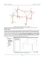
In this example, the aim is to design reinforcement of a concrete column of a hexagonal crosssection. With 200mm depth of the section and 2000mm length, the column is subject to axial
compression and biaxial bending. The actions in the ultimate limit state are: Nx= 400kN, My=
2.33kNm and Mz= 5.46kNm; in serviceability limit state: Nx= 350kN and My= 2.00kNm.
Concrete of strength class C30/37 X0 and steel of grade B500 are used in the design.
Creating a new job
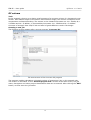
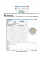
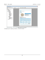
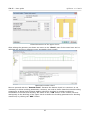
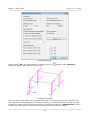
The following screen appears after running program "Concrete 3D":
The start screen of the Concrete 3D program
The program enables calculating unlimited number of sections per job, in this example only
one section is calculated. In the "General project data" section of the start screen, the job
name, description and other project identification data can be entered. After clicking the "Edit"
button, we first enter the job name:
4
FIN EC – User guide
© Fine s. r. o. 2013
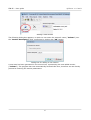
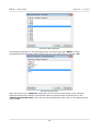
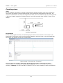
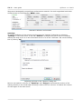
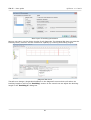
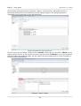
"General project data" dialog box
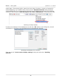
In the "General project data" dialog box, identification data of the job can be entered; these
can later be displayed in the header or footer of the output files. In the start screen we can
also change settings of some of the calculation parameters and thus affect programs general
functionality ("Calculation options" and "Program options" frames in the lower part of the
screen).
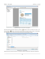
Prior to commencing any work, it is advisable to save the job; this can be done either using "
" button, or in the main menu clicking on File – Save As, or using the "Ctrl+S" shortcut.
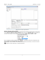
Saving job
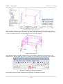
Now we can proceed to entering a new section by clicking the "Add Section" button in the
upper part of the program’s control tree on the left-hand side.
5
FIN EC – User guide
© Fine s. r. o. 2013
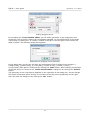
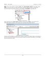
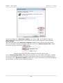
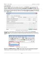
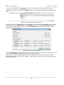
Adding a new section
The following dialog box appears, in which we can enter the section’s name ("Column") into
the "Section description" field, confirming by clicking the "OK" button.
Dialog box for adding a new section
A new item has been generated in the control tree, representing the new added section
("Column"). The program has now automatically selected this item; therefore we can directly
proceed to entering the section parameters.
6
FIN EC – User guide
© Fine s. r. o. 2013
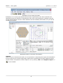
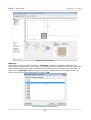
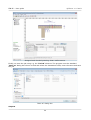
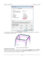
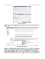
Dialog box for section parameters
Section, Material, Reinforcement
At first it is necessary to enter the basic geometrical and material characteristics of the section
in the "Section, Material, Reinforcement" frame. From the "Member type" drop-down list
we select the function of the member in the structure: beam, slab, column or wall.
In our example we select member type "column". This selection affects the assessment and
design checks of the reinforcement arrangement.
As a hexagon is not included in the library of pre-defined cross-sections, we need to use the "
" button to define geometry of a general polygon:
7
FIN EC – User guide
© Fine s. r. o. 2013
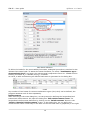
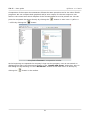
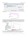
Adding polygon points.
In the dialog box "Cross-section editor" we can define geometry of any polygonal crosssection as a set of points. Having the coordinates available, we can define each of the points
numerically by clicking the "+" button, located in the bar in the left upper corner above the
table of points. The following dialog box appears:
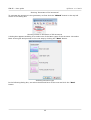
Dialog box for polygon points definition
In this dialog box, one by one we enter the coordinates of all six points of the polygon: [0,058;0,100], [0,058;0,100], [0,115;0,000], [0,058;-0,100], [-0,058;-0,100], [0,115;0,000]. Each point is confirmed by clicking the "Add" button; after entering coordinates
of the last point, we return to the "Cross-section editor" dialog box by clicking the "Cancel"
button.
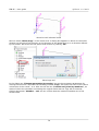
The geometry of the cross-section appears on the right side of the dialog box; we can change
the points coordinates either directly in the table on the left side or graphically on the right
side. We close the dialog box by clicking the "OK" button.
8
FIN EC – User guide
© Fine s. r. o. 2013
Definition of polygon’s geometry
We proceed with defining the material properties in "Materials" dialog box which is run by
clicking the "Material" button in the "Section, Materials, Reinforcement" dialog box.
Assuming the column is located inside of the structure we select the "Exposure class X0 – no
risk of corrosion or attack", as the column is not in contact with outside environment.
Subsequently we define the material properties of concrete and longitudinal and transversal
reinforcement. We can select standardized materials from the library of pre-defined materials
clicking the "Catalogue" button at relevant lines.
"Materials" dialog box
For concrete we select the strength class "C30/37" and close the dialog box by clicking "OK".
9
FIN EC – User guide
© Fine s. r. o. 2013
Concrete class selection
Proceeding to definition of the steel properties, we select the grade "B500" for both
longitudinal and transversal reinforcement and close the dialog box by clicking "OK".
Steel grade selection
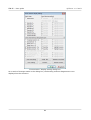
After returning to the "Materials" dialog box we can check the summary of the selected
materials and confirm whether the selected class of concrete fulfils requirements on the
"Indicative strength class" given by the selected Exposure Class. We exit the dialog box by
clicking "OK".
10
FIN EC – User guide
© Fine s. r. o. 2013
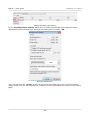
Indicative strength class check in "Materials" dialog box
Loads
After defining the geometry of the section and material properties, we can proceed either with
defining the reinforcement or loads. In our example we first define a load case because then
we are able to check the results of the reinforcement assessment during its definition. To
create a load case, we click the "Add" button located under the "Loads" table. In the "New
load" dialog box we select a "Combination type" depending on which combination has been
used to obtain the design forces and bending moments and for which design situation the
assessment shall be carried out. The following options are available:
Basic design
• Forces and bending moments have been obtained from the basic
(ULS)
combination for persistent and transient design situations according
to EN 1990, equations 6.10 resp. 6.10a and 6.10b. These loads are
used for basic assessment of cross-section’s capacity in the ultimate
limit state.
Accidental design • Forces and bending moments have been obtained from the
(ULS)
combination for accidental design situations according to EN 1990,
equation 6.11. These loads are used for assessment of cross-section’s
capacity in accidental design situations in the ultimate limit state
(partial safety and material factors for accidental design situations are
used).
Characteristic
• Forces and bending moments have been obtained from the
(SLS)
characteristic combination according to EN 1990, equation 6.14.
These loads are used for assessment of the stress limitation
(serviceability limit state).
Quasi-permanent • Forces and bending moments have been obtained from the quasi(SLS)
permanent combination according to EN 1990, equation 6.16. These
loads are used for assessment of the crack widths in the serviceability
limit state.
Subsequently we enter the forces and bending moments acting on the cross-section; in our
example the axial force is N= -400kN (negative value denotes compression) and the bending
moments are My= 2,33kNm and Mz= 5,46kNm.
Also, we should enter the "Load duration coefficient", i.e. the ratio of quasi-permanent and
total loads for calculation of the creep coefficient. If the exact value is not available, we can
leave the conservative value of 1.00, which means that the total load is considered quasipermanent in the calculations. The new load is confirmed by clicking the "Add" button and
"Cancel" to exit the dialog box.
11
FIN EC – User guide
© Fine s. r. o. 2013
New loads definition
To define the loads for the serviceability limit state, analogical procedure is used as for the
ultimate limit state loads. To assess the stress limitation, we select "Combination type –
characteristic (SLS)" and enter the relevant axial compressive force N= -350kN and the
bending moments My= 2.00kNm and Mz= 0.00kNm.
As result, a table summarizing all defined load cases is generated in the dialog box.
Loads
Any number of load cases for various combination types (ULS, SLS) can be defined; the
program assesses each of them separately.
Reinforcement
After returning to the main dialog box, we can proceed to defining the longitudinal and
transversal reinforcement. We open the dialog box "Edit reinforcement sector" for
longitudinal reinforcement definition by clicking on the "Reinforcement" button in the
"Section, Material, Reinforcement" frame. In this dialog box, we can define the
reinforcement either numerically in the table on the left-hand side or graphically in the right
12
FIN EC – User guide
© Fine s. r. o. 2013
part of the dialog box.We can also take advantage of a simplified approach by clicking "
"
and then the "Generate" button in the left lower corner of the dialog box. In our example we
will use this option.
Simplified definition of reinforcement
We can now easily define required longitudinal reinforcement using 16mm bars in each corner
of the cross-section, entering 3 layers with appropriate covers:
Definition of reinforcement
13
FIN EC – User guide
© Fine s. r. o. 2013
After defining reinforcement we can immediately check in the lower part of the dialog box that
the area of the reinforcement is sufficient and passes design criteria with 34.1% utilization by
bending. In the section "Information on reinforcement" we can also confirm that the
detailing requirements given by the code are satisfied. Finally we need to check if the covers
are correctly defined. Having a column with stirrups, the option "Min cover and stirrups" is
selected in the "Cover" section of the dialog box. The program will calculate the minimum
required cover of the longitudinal reinforcement as sum of the minimum cover given by the
code and the diameter of the stirrups. The calculation can be checked in the dialog box opened
by clicking "Minimum cover" button:
Minimum cover calculation
As it is not necessary to change the settings of cover calculation, we can exit the dialog box by
clicking "OK" and return to the dialog box for longitudinal reinforcement definition. To check
whether the geometry of the longitudinal reinforcement satisfies requirements on minimum
covers, we can run the assessment by clicking "Check of cover".
14
FIN EC – User guide
© Fine s. r. o. 2013
Covers check result
The check returned a positive result, therefore we can return to the main dialog box by clicking
"OK".
Shear reinforcement
We can proceed to defining the shear reinforcement by clicking the eponymous button in the
main screen.
We specify 10mm diameter boundary stirrups with 150mm spacing:
Shear reinforcement definition
15
FIN EC – User guide
© Fine s. r. o. 2013
Buckling
The next step is defining the buckling parameters. Firstly we need to tick "Calculate buck.
Y/Z" boxes followed by entering the nominal lengths of the column for both directions, based
on which the effective buckling lengths will be calculated. For a column simply supported on
both ends, the effective buckling lengths equal to the nominal. Defining different boundary
conditions can be done by clicking the "
" buttons for each direction.
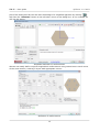
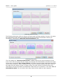
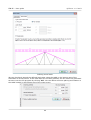
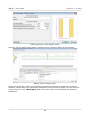
Defined buckling parameters
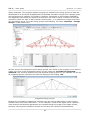
After defining the buckling parameters, two distinct areas of capacity are shown in the
interaction diagram: thin dashed line denotes capacity of the member without influence of
buckling and thick line denotes the capacity reduced by buckling effect. To check position of a
defined load case in the "Interaction diagram" we need to enter the relevant axial force
level; in our example N= -400kN. Program will create a cut through the interaction diagram on
this level showing the position of the defined load case:
Defining a cut through the interaction diagram
Because we completed definition of all parameters, it is recommended to save the job by
clicking "
" on the toolbar or using shortcut "Ctrl+S". The actual state of the job during
work may not be identical to the one saved on disk; this is indicated by "*" in the program
window header. In such case it is advisable to save the job.
16
FIN EC – User guide
© Fine s. r. o. 2013
Indication of non-saved job state
Indication of non-saved job stateAs all structural requirements have been checked and
satisfied during the definition of parameters and as the main dialog box indicates that the
section passes design checks in both ultimate and serviceability limit states, the job can be
considered finished.
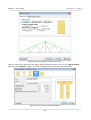
Assessed section in Concrete 3D program
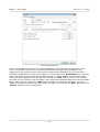
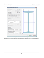
Outputs
When the job is finished and saved, we can proceed to composing the output documentation.
First we print out a concise single page output which summarizes all input data and design
checks results. Composition of this output is run by clicking "File" and "Graphic output" or "
" in the toolbar.
17
FIN EC – User guide
© Fine s. r. o. 2013
Graphical output of Concrete 3D program
We can print the document directly by clicking "
" button or save it on disk as *.pdf or *.rtf
file by clicking "
" button. We use the second option and save the file on disk. In the dialog
box "Save as" we can enter the file name and select the destination folder.
Saving file in *.pdf format
Apart from this concise document, we can also compose a detail text output by clicking the "
18
FIN EC – User guide
© Fine s. r. o. 2013
" button in the toolbar or selecting "File" and "Text/Graphic output" in the main menu.
However, as we are still in the print and export document dialog box we can change the
document type to text output directly in the toolbar’s "Document" drop-down list.
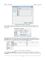
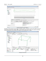
Change of output type
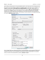
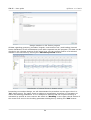
After switching to the "Text output" mode we can set in the "Editor" which parts of the
assessment will be included in the output and how detailed the output shall be.
Printing options of text outputs
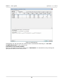
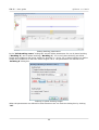
Program will immediately re-generate the output to reflect each change made in the settings in
the tree on the left-hand side. Once the output contains all required information, we can again
save the document on disk.
19
FIN EC – User guide
© Fine s. r. o. 2013
Generated text output
Completing the outputs generation, our work is done.
20
FIN EC – User guide
© Fine s. r. o. 2013
Punching shear
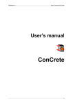
Task
In this example, the task is to design reinforcement against punching of a corner column of
200 x 200 mm square cross-section through a 200 mm thick reinforced concrete slab. The
column is located 500 mm from the edges of the slab, which is weakened by an opening of 150
x 500 mm located as per the following sketch. Concrete strength class C25/30 is used in the
design.
Problem’s geometry
Project data
In the main program window, all essential project data can be entered in the frame in the
bottom part. Definition modes can be switched between using the tree on the left hand side;
the rest of the window serves as a model space.
Main window of the program "Punching"
First we enter the company data which will be later used when composing the output
documentation. The dialog box "About the company" can be run from the main menu
selecting "Settings". In the first tab for instance, we can enter company’s name and address.
21
FIN EC – User guide
© Fine s. r. o. 2013
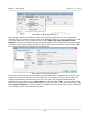
Essential company data in the "About the company" dialog box
In the second tab we can enter the company’s logo which can later be displayed in the header
of the output documentation. The logo can be loaded as an image of any usual format such as
*.bmp, *.jpg, *.ico etc. To import the logo we run the dialog box by clicking "Load".
Button for loading the logo file
For selecting files, the standard Windows user interface is used. After opening the folder
22
FIN EC – User guide
© Fine s. r. o. 2013
containing the file, we load the file by clicking the "Open" button.
Logo file selection
A preview of the logo is subsequently displayed; its size will be automatically adjusted to the
graphic layout of the program’s output.
A logo loaded to the program
In the last tab "Employees", we can enter a list of company’s employees from which we can
select the author of the project. New employees are entered by clicking the "Add" button.
23
FIN EC – User guide
© Fine s. r. o. 2013
Entering a list of employees
We exit the dialog box "About the company" by clicking "OK". The company’s data are
shared with all EC programs and can be therefore used in other programs of the package.
Basic settings
After entering data in the "About the company" dialog box we return to the main screen.
Here we can enter essential information about the job in the "General project data" dialog
box which opens by clicking the "Edit" button.
Opening "General project data" dialog box from the main window
In the "General project data" dialog box we can enter e.g. job’s name, description, remarks
etc. It is also possible to select the author of the project from the list of the employees which
we created in the "About the company" dialog box. All this information can be later displayed
in the headers or footers of the output documents.
24
FIN EC – User guide
© Fine s. r. o. 2013
Selecting job’s author from list in "General project data" dialog box
Once we have finished entering the project data, we exit the dialog box by clicking "OK". Then
we can proceed to the next step by clicking the "Geometry" button in the tree on the lefthand side.
Geometry
In this dialog box, we first select the column’s cross-section. Clicking the "
"
button we open the catalogue of pre-defined shapes. Then we select a rectangle and enter the
dimensions.
Catalogue of pre-defined cross-section shapes
In the "Geometry" section of the main screen we enter the slab thickness, select the "corner"
column type and define the edge distances. The structural layout instantly appears in the
model space.
25
FIN EC – User guide
© Fine s. r. o. 2013
Defining job’s geometry
Materials
Proceeding to the next item of the tree - "Materials", another sub-window appears in the
main window’s bottom part. In this section we need to specify materials for concrete and slab’s
longitudinal and punching shear reinforcement. As we are using a standard concrete class, we
click on the "Catalogue" button and open the list of available concrete strength classes. We
select C20/25 and exit the dialog box by clicking "OK".
Concrete strength class selection
26
FIN EC – User guide
© Fine s. r. o. 2013
We proceed analogically to specifying reinforcement material. For both longitudinal and shear
reinforcement we will select the "B500" grade.
Materials’ definition sub-window
Openings
To simplify definition of the opening we first open the "Options" dialog box by selecting
"Settings" in the main menu. In the tab "General" we adjust the grid to suit our needs by
defining the step as 0.5 m in the X direction and 0.15 m in the Y direction. We exit the dialog
box by clicking "OK".
Adjusting grid step in the "Options" dialog box
Now we can switch in the tree to "Openings" and "Polygon" and draw the contour of the
opening directly in the model space clicking in each of its four corners. To finalize the contour
we click again on the first corner.
27
FIN EC – User guide
© Fine s. r. o. 2013
Definition of opening in model space
Other data
In this section of the tree we define the loading and longitudinal reinforcement of the slab as
VEd = 100 kN and 8 of 12 mm diameter bars per meter run.
Slab loading and reinforcement definition
Calculation
Switching to the last item of the control tree "Calculation" we can proceed to carrying out the
design checks of the punching shear reinforcement. First we need to select the shear
reinforcement type; in our example we will use "concentrated stirrups". Then we can either
define the reinforcement manually in the table in the definition frame or we can let the
program design the reinforcement automatically. Choosing the latter, we run the automatic
reinforcement design by clicking the "Design" button.
28
FIN EC – User guide
© Fine s. r. o. 2013
Button for automatic design of punching reinforcement
In the "Reinforcement generation" dialog box we can define invariable reinforcement
parameters; other parameters will be defined automatically. Ticking the "Use row spacing"
box and entering a value we define fixed stirrup spacing 100 mm; the position of the first row
and the stirrups diameters we leave to be designed automatically.
Dialog box for automatic design of reinforcement
After closing the dialog box by clicking "OK" the reinforcement is designed to reach required
capacity and fulfil all detailing requirements.
29
FIN EC – User guide
© Fine s. r. o. 2013
Designed and checked punching shear reinforcement
Finally, we save the job using e.g. the "Ctrl+S" shortcut. The program runs the standard
"Save as" dialog box where we find and select the destination folder, enter the name and save
the job.
"Save as" dialog box.
Outputs
30
FIN EC – User guide
© Fine s. r. o. 2013
Composition of the output documentation follows the same procedure as for the other FIN EC
programs. We can compose both graphical and/or text output; for the text output we can
select in the control tree which chapters of the documentation are to be printed out. We can
print the composed document directly by clicking the "
*.rtf file by clicking the "
" button or save it as a *.pdf or a
" button.
Output documentation composition window
At the beginning we imported the company’s logo into the program, now we can switch on
displaying the logo in the documents header in the "Header and footer" dialog box. We run
this dialog box by selecting it in the "Document" section of the main menu or directly by
clicking the "
" button in the toolbar.
31
FIN EC – User guide
© Fine s. r. o. 2013
Displaying logo in document’s header
After ticking the "insert company logo" box, the logo appears in the headers of all
documents.
Header with the company’s logo
32
FIN EC – User guide
© Fine s. r. o. 2013
Timber truss
Task
In this example, the task is to design a symmetric roof timber truss of 13 m length and 25
degrees of the roof pitch. The truss consists of timber members of class C24 and 40 mm
thickness; the spacing of the trusses is 1 m centres. The truss is subject to dead load 0.2
kN/m from both roofing and ceilings and to snow load 1.0 kN/m according to the Snow area 2
of the Czech snow map.
Setting up project
After running the program 2D, the main screen appears, consisting of the model space on the
right-hand side, the control tree on the left-hand side and the input table in the bottom part.
The table displays the project information which can be later used in headers and footers of
the output documents. To enter or edit the project information, we can run the relevant dialog
box by clicking the "Edit" button.
Button for running the "Project information" dialog box
In the dialog box we can enter e.g. the job title or the project author. After entering all
necessary data we exit the dialog box by clicking the "OK" button.
33
FIN EC – User guide
© Fine s. r. o. 2013
"Project information" dialog box.
Before proceeding with work we should save the job using e.g. the "Ctrl+S" shortcut. The file
name is entered and the destination folder selected in the standard ‘Save as’ window.
"Save as" window.
Structure generation
We can define the truss geometry either by entering individual nodes and members or we can
simply make use of the Generator of 2D structures. In our example we will choose the latter
approach. The generator is run by clicking the "Generate" button in the "Topology" section of
the control tree.
34
FIN EC – User guide
© Fine s. r. o. 2013
Running "Generator of 2d structures"
To generate the structure in the generator, we first click the "Wizard" button in the top left
corner of the dialog box.
Running wizard in Generator of 2D structures
A dialog box appears enabling us to select one of the basic types of the structure. We select
Basic truss types and proceed to the next step by clicking the "Next" button.
Selecting structure type
In the following dialog box, we select the desired form of the truss and click the "Next"
button.
35
FIN EC – User guide
© Fine s. r. o. 2013
Selecting structure form
The following dialog box offers a selection of basic types of filling members’ layouts. We select
the desired filling type and in the bottom left corner we switch off automatic entering of
verticals by unticking the "Generate vertical members" box.
Selecting filling type
The next dialog box "Structure dimensions" enables defining the main dimensions of the
truss. If we enter the pitch and the length, the program will automatically calculate the height
of the truss. In the field "No. of bays on B.C." we define into how many segments the bottom
chord will be divided by nodes. Additional nodes may be inserted between the main nodes of
the upper and the bottom chords. In these nodes, the exact values of internal forces and
deformations will be calculated and additional nodal forces can be defined. In the field "No. of
intermediate joints" we can define how many nodes will be added to each segment.
36
FIN EC – User guide
© Fine s. r. o. 2013
"Structure dimensions" dialog box.
After definition of the truss dimensions, we need to specify cross-sections and materials of
individual truss members. This will be done in the following dialog box "Profiles in groups" in
which we can specify profiles and materials separately for the upper and the bottom chords
and the filling studs by clicking the "Profile" button in the relevant tabs. However, we will use
a quicker approach specifying first the material and profile for all members by clicking the
"Global profile" and then only changing the profiles of the upper and the bottom chords.
"Profiles in groups" dialog box
After clicking the "Profile" button, the "Cross-section editor" dialog box appears on screen.
In this dialog box we select "Timber" and "Solid squared" type and define the dimensions of
37
FIN EC – User guide
© Fine s. r. o. 2013
the rectangular profile as h = 80 mm and b = 40 mm.
Defining cross-section dimensions
After confirming the dimensions by clicking "OK", the "Catalogue of materials – timber"
dialog box appears, offering a selection of the standard timber strength classes. We select C24
and confirm by clicking the "OK" button.
Selection of strength class
After confirming, the selected material and cross-section data appear in all three tabs of the
"Profiles in groups" dialog box.
38
FIN EC – User guide
© Fine s. r. o. 2013
Editing profiles of upper and bottom chords
Now we change the profiles of the upper and the bottom chords. First, in the "Upper chord"
tab using the "Profile" button, we set a Pi-shaped profile and enter the dimensions.
Upper chord’s cross-section dimensions
39
FIN EC – User guide
© Fine s. r. o. 2013
Analogically, we define a compound cross-section of the bottom chord.
Dimensions of bottom chord’s compound cross-section
After changing the chords’ profiles we exit the "Cross-section editor" by clicking "OK". The
generated truss is now displayed on screen. We can go back to any of the previous steps using
relevant buttons in the "Structure" frame to the left from the model space. In the frame in
the bottom of the screen, the tables for managing load cases and members are organized into
tabs.
Tabs for editing load cases
We select the "Load cases, load’ tab and begin to define the load cases. Firstly, selecting
"Self weight" we define a load case, which will contain automatically generated loads from
the truss’s self weight. In the dialog box we can edit the name of the load case or load factors.
40
FIN EC – User guide
© Fine s. r. o. 2013
Parameters of "self weight" load case
Adding a new load case is confirmed by clicking "OK" and the loads generated from the self
weight into this load case are instantly displayed in the model space. We continue with adding
loads from the roofing, using the "Roofing" button. The "Roofing load" dialog box contains
two tabs; the first is for specifying the load case parameters (similarly to self weight), in the
second the load magnitude is defined. We switch to the second tab to enter the value 0.2
kN/m and add the load case by clicking "OK". Then we exit the dialog box by clicking the
"Cancel" button.
Tabs in the ‘Roofing load’ dialog box
41
FIN EC – User guide
© Fine s. r. o. 2013
We repeat the same procedure to define the ceiling loads.
Defining ceiling loads.
For snow loads, due to the variable nature of the loading, the dialog box for the load case
properties contains different data than that for the permanent loads. Short or medium term
loading type can be selected, as well as the "Category" which sets the combination factors in
accordance with EN 1990.
42
FIN EC – User guide
© Fine s. r. o. 2013
Snow load properties
In the second tab, we can define the loads separately for the left and the right side of the
truss; it is possible to define non-uniformly distributed load caused by snowdrifts. The
magnitude of the loading can be entered as the basic value obtained from the snow map;
automatic redistribution on the inclined plane is run by ticking the "Recalculate" box. First we
define the load case with uniformly distributed loads 1.0 kN/m applied to both halves of the
truss; the load is applied to the structure by clicking the "Add" button. Then we can change
the value s1 to 0.5 kN/m; thus we obtain a non-uniformly distributed load case which we again
apply to the truss by clicking the "Add" button. Finally, we switch the values s1 and s2 to
obtain a load case symmetric to the previous. We apply it by clicking the "Add" button and the
"Cancel" button to exit the dialog box.
43
FIN EC – User guide
© Fine s. r. o. 2013
Defining snow loads
We can check and amend the defined load cases using the table in the bottom part of the
Generator of 2D structures. If the load cases are correctly defined, we can insert the generated
structure into the 2D program by clicking "OK". We can define structure placing and rotation in
the table located in the bottom part of the main screen.
44
FIN EC – User guide
© Fine s. r. o. 2013
"Insert structure" table.
After inserting, the truss is displayed in the program’s model space. Geometry can be further
edited in the "Topology" part of the control tree, load cases and loads can be edited in the
"Loads" part. Only the active load case selected from the drop down list in the upper part of
the control tree is displayed in the model space.
Displaying particular load cases
Definition of combinations
We can proceed to defining the load combinations which are defined separately for the ultimate
and the serviceability limit states. First we define the combination for the ultimate limit state.
We switch to "1st order combination ULS" in the control tree and run automatic definition of
combination by clicking the "Generate" button in the table of combinations.
Button for automatic definition of combinations.
45
FIN EC – User guide
© Fine s. r. o. 2013
The automatic generation of combination is run in the "Generator of combinations" dialog
box. The dialog box contains three tables. In the first, the load cases which act simultaneously
are combined. In the second, we can set mutual exclusion of some load cases in one
combination. The last table contains a list of variable loads which shall be considered main. In
our example, we need to exclude simultaneous action of the defined snow load cases; hence
we create a new exclusion group by clicking the "Add" button in the table "Excluded
interaction of load cases".
"Generator of combinations" dialog box.
In the "Excluded interaction" dialog box we select the load cases S4, S5 and S6 and confirm
selection by clicking the "Add" button.
46
FIN EC – User guide
© Fine s. r. o. 2013
Defining mutual exclusion of load cases
After closing the dialog box a new group of mutually exclusive load cases appears in the
relevant table. Thus it is guaranteed that only one of these load cases can appear in one
combination.
Added group of mutually exclusive load cases
Once we have finished entering data, we can create the combinations by clicking the
"Generate" button. A list of the generated combinations appears in the table in the bottom
part of the screen; we can add, edit or erase the combinations as necessary. We can also
display the list in a comprehensive table by clicking the "Table" button.
Button for running "Table of combinations"
In the "Table of combinations" we can check the generated combinations; for the active
combination, a detail description including the used load factors is displayed in the bottom part
of the table.
47
FIN EC – User guide
© Fine s. r. o. 2013
Table of combinations
Analogically we will generate the characteristic combinations switching to "1st order
combinations SLS" in the control tree.
Calculation and results display
Now we can finally proceed to running the "Calculation" of internal forces by clicking the
eponymous button in the control tree.
48
FIN EC – User guide
© Fine s. r. o. 2013
Running calculations
The "Calculations properties" dialog box appears; we can confirm the settings by clicking
"OK" after which the calculation is executed and a window with information about the
calculation process displayed. After clicking the "Cancel" button, program switches
automatically to post-processor.
"Calculation properties" dialog box.
After finishing calculation, deformation resulting from the combination No. 1 is displayed in the
49
FIN EC – User guide
© Fine s. r. o. 2013
model space. The program offers, apart from many other functions, a variety of settings for
results displaying, e.g. enables saving views into the "Named selections" and printing all
views subsequently. In our example we will show how to display the envelope of the bending
moments. First we select "ULS, envelope of 1st order combinations" in the drop down list.
Selecting envelope display
To define an envelope of all combinations we click the "All" button in the dialog box; thus all
combinations in the list on the left-hand side are automatically selected.
Selecting combinations for envelope
Then we run the "Cross-section display settings" dialog box and select "Bending
moment".
50
FIN EC – User guide
© Fine s. r. o. 2013
"Cross-section display setting" dialog box.
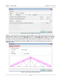
After confirming, the envelope of bending moments is displayed on the structure.
Envelope of bending moments on structure.
Now we proceed to design checks of the structure’s cross-sections. First we switch to the "Des.
groups" in the control tree. The structure consists of total of 11 elements, representing 11
51
FIN EC – User guide
© Fine s. r. o. 2013
design members. The program enables merging the members into design groups so that the
assessment is as quick and straightforward as possible. Members merged into a design group
are checked as one member; the loading is however considered on all members separately.
This approach is beneficial for instance in case when we need to check a number of concrete
columns in which we want to have unified reinforcement – it is sufficient to merge all of them
into one design group. To create design groups automatically, we select "Generate – Design
Groups" in the control tree.
Generating design groups
We can check in the dialog box which design groups were found by the program. If we want to
create only some of the suggested groups, we can untick the "Consider all generated
elements" box and then proceed only with selected design groups. In our example we will use
all suggested groups, therefore we close the dialog box by clicking "OK".
Suggested design groups
Because the orientation of particular elements vary we need to appreciate in case of which
members this could cause difficulties – in our example it could be the upper chord. However;
cross-sections and buckling parameters are constant along the length of the upper chords,
therefore varying axes orientation should not influence the results of the assessment.
52
FIN EC – User guide
© Fine s. r. o. 2013
Notice on different element’s orientation
Individual elements have been merged into 5 design groups and one design member. We can
name the members and groups in the table in the bottom part of the screen.
Table with entered names of design members and groups
Now we can proceed to the design itself. We select "Design" and "Timber" in the control tree
and run the timber structures design program by clicking the "Run program" button.
Running timber structures design program
Members design
Program 2D Timber is run with all design members and groups automatically imported.
53
FIN EC – User guide
© Fine s. r. o. 2013
Design members in 2D Timber program
All data regarding geometry (members’ lengths, cross-sections etc.) and loading (internal
forces distribution for all combinations) have been imported into the program. The data can be
checked in the relevant sections of the control tree. We can confirm position of a selected
member in the structure by clicking the "Structure preview" button.
Distribution of internal forces in bottom chord
Proceeding to members design, we will demonstrate the procedure on the upper chord i.e.
"D1" design group. The upper chord is subject to compression; therefore it is necessary to
define the buckling parameters. In our example we assume that out-of-plane buckling is
restrained by purlins at 0.6m centres. We switch to "Buckling" in the upper chords section of
the control tree and run the buckling parameters dialog box by clicking the "Edit" button.
54
FIN EC – User guide
© Fine s. r. o. 2013
Editing buckling parameters
In the "Edit buckling sector" dialog box we can define parameters for out-of-plane buckling
("Buckling Z") and in-plane buckling ("Buckling Y"). For out-of-plane buckling we define
simple end conditions and sector length for buckling Lz= 0.6m; for in-plane buckling we define
simple end conditions as well with sector length 2.4 m. The parameters are defined in the
"Buckling Z" dialog box.
Defining in-plane buckling length
When the parameters are defined for both directions we can close the dialog box by clicking
"OK".
55
FIN EC – User guide
© Fine s. r. o. 2013
Defined buckling parameters
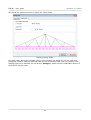
We switch to the "Check" section of the control tree and run the calculations by clicking the
"Calculate" button. In the model space, the cross-section utilization curve is displayed along
the length of the member; the critical section with the highest utilization is checked in the
bottom right corner of the screen. If it is necessary to display detail checks in other sections,
these can be added using the table in the bottom part of the screen or simply by doubleclicking in the selected location of the utilization diagram in the model space.
Members check
Because the maximum utilization of the member is very low, we can reduce the size of the
cross-section. We switch to the "Section" part of the control tree and run the "Cross-section
editor" dialog box where we can edit the cross-section geometry.
56
FIN EC – User guide
© Fine s. r. o. 2013
Edited dimensions of the upper chord
After editing the geometry as shown we return to the "Check" part of the control tree and recalculate the structure, obtaining more acceptable check results.
Optimized member check
Now we proceed with the "bottom chord". Because the bottom chord is in tension it is not
necessary to define buckling parameters. However, we need to define lateral torsional buckling
parameters as lateral and torsional stability should be checked in members subject to
combination of tension and bending. We switch to the "LTB" section of the control tree and
analogically to the buckling of the upper chord we define the buckling parameters for bending
moment My by clicking the "Edit" button.
57
FIN EC – User guide
© Fine s. r. o. 2013
Editing buckling parameters
In the "Buckling sector editing" dialog box we define the LTB effective length and select
appropriate beam and load type. We close the dialog box by clicking "OK".
Buckling parameters
Then we switch to the "Check" section of the control tree again and carry out the members
design check. Also for this member the utilization is too low therefore we edit the cross-section
again.
58
FIN EC – User guide
© Fine s. r. o. 2013
Editing geometry of the bottom chord
We carry out the design check again confirming more economic design of the member.
Bottom chord’s design check
Finally, the diagonals remain to be checked. Because the diagonals’ properties are almost
identical, we can define the calculation parameters for all of them together. This can be done
using a function in the "Mass input" part of the main menu. First we define the buckling
parameters.
59
FIN EC – User guide
© Fine s. r. o. 2013
Mass input of buckling properties
Even though it would be sufficient to define the buckling parameters for the compressive
members only, it is easier to assign them to all diagonals. Hence we select members D1 to D4
on the left-hand side. In the right part we tick the "Take over sector geometry from
analysis" so that the program will use the actual lengths of the members as buckling lengths.
Finally we define simple supports at both ends for both y and z directions. After clicking "OK"
the entered parameters are assigned to all diagonals.
Mass input of buckling parameters
We continue with defining lateral torsional buckling parameters. Diagonals are generally only
subject to axial forces therefore the LTB checks are not required; however, due to their self
weight, small bending moments can occur. In such cases, the program demands lateral
torsional buckling checks. In the "Mass input" section we select "LTB"; in the left part of the
dialog box we again select all diagonals and from drop down list in the right part we select "do
not consider buckling". Thus the influence of lateral torsional buckling will not be considered
in the design checks of the selected members.
60
FIN EC – User guide
© Fine s. r. o. 2013
Mass input of buckling parameters
Now we can carry out the design checks for all diagonals. The diagonal D6 does not pass the
buckling check, however we can increase its capacity by reducing its buckling length.
Diagonal D6 check
Therefore we design a longitudinal stiffener in the diagonal’s centre which will reduce its
buckling length to half. In the "Buckling" section of the control tree we adjust the buckling
length in the "Buckling Z" dialog box.
61
FIN EC – User guide
© Fine s. r. o. 2013
Adjusting buckling length
After re-calculating, the diagonal passes the design checks.
Checked design members
Now all design members and groups in the structure are checked, therefore we can exit the
design module by clicking "OK". Program 2D has recognized that some members were
changed. Because the stiffness of individual members changed and thus different internal
forces can act on some of the them, it is necessary to re-calculate the structure. The program
automatically offers this option. If we select "No", the program will erase results and return to
the pre-processor. In our example, we select "Yes" after which the structure is re-calculated.
62
FIN EC – User guide
© Fine s. r. o. 2013
Question on re-calculating structure
After finishing the calculation, the program updates distribution of internal forces and
deformations and erases the results in the design module. Therefore we run the design module
again and make use of the command "Check All" located in the bottom part of the control
tree. We do not have to re-define all parameters as they are saved after previous definition.
The module will carry out design checks for all members and inform us about the results.
Members’ design checks results
After returning to the program 2D, members which passed the checks are marked in green and
the members which did not in red. In our case, all members are marked in green; therefore
the structure’s design is completed.
63
FIN EC – User guide
© Fine s. r. o. 2013
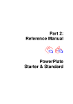
3D structure
Task
In this example, the task is to design and check the 3D structure shown on the sketch below.
The columns are circular hollow sections and the beams are I-sections, both made of steel of
the grade Fe 360. The beams are subject to vertical uniformly distributed load 18 kN/m; the
lateral loading on 2 of the columns is trapezoidal with top magnitude 12 kN/m and bottom
magnitude 19 kN/m. The columns are fixed to the concrete underlay.
Geometry of the structure
After running the program 3D, the following screen appears.
Program’s main screen
Structure’s definition
In this example, we will not use the "Generator of 3D structures"; instead we will define the
structure’s geometry by entering individual joints and members. Thus we can show alternative
64
FIN EC – User guide
© Fine s. r. o. 2013
ways of creating and editing structures. Using this approach, there are more ways how to
define the structure’s geometry. In our example we opted for the following:
• first we define a frame (2 columns and a beam)
• we define the loading on members
• we copy the frame to obtain a 3D structure
• we define the transverse beams’ properties including loading
This approach has not been selected because it would be ideal or simplest, but because it gives
us the opportunity to explore more of the program’s functionalities.
First we save the project, naming it e.g. "3D structure". The name is displayed in the main
screen’s header and it will also be exported to the design programs.
In the control tree in the left part of the screen, we select "Joints" and "Add abs.". A dialog
box for joint prototype’s definition appears; its purpose will be further explained.
Absolute joint prototype definition
The purpose of the dialog box "Absolute joint prototype" is to define the fixed directions of
the entered joints. First we will define the joints of the fixed column bases either by ticking the
"fixed" boxes for all directions, or by clicking the button with a symbol of a fixed base on the
right-hand side of the dialog box. We confirm the support definition by clicking "OK".
65
FIN EC – User guide
© Fine s. r. o. 2013
Absolute joint prototype defined as a fixed base
The dialog box "Absolute joint prototype" moves into the bottom definition frame. Now we
can enter nodes with coordinates [0,0,0] and [4,0,0] in the model space; for easier entering
we make use of the default grid step of 1 m. We can check the coordinates in the status line of
the main screen. During the nodes definition, the information about the joint’s prototype
remains in the definition frame, thus we can always control which joint (or member or loading)
is being defined and we can easily change the prototype’s parameters to continue with
definition.
For upper nodes’ definition, we need to change the prototype’s parameters; as they will not be
supported, we untick the fixity in all directions (or we use the button with a symbol of a simple
node on the right-hand side). Then we enter the nodes with coordinates [0,0,2] and [4,0,2].
Definition of the upper nodes
66
FIN EC – User guide
© Fine s. r. o. 2013
Because the upper joints are now aligned to the grid step, their coordinates in the z-direction
are 2.0 m instead of 2.35 m as given in our example. We therefore edit the coordinates of
these joints by selecting them in the table located below the model space (the active joint is
highlighted in bold) and click the "Edit" button.
Editing joints
In the dialog box "Properties of absolute joint" we change the Z coordinate to 2.35 m. We
confirm the definition by clicking "OK" and edit the fourth joint analogically.
Change of absolute joint’s coordinate
Now we can define the members in the same way as the joints. We switch to "Members" and
"Add" in the control tree; similarly to joints definition, a dialog box with member prototypes’
properties appears. In this dialog box, we define the cross-section using the "Profile" button
and selecting the section type "Steel" and "Solid welded" in the following dialog boxes.
67
FIN EC – User guide
© Fine s. r. o. 2013
Selection of the section type
In the "Cross-section editor", we select a circular tube and define the 200 mm diameter and
20 mm wall thickness.
Defining cross-section dimensions
In the following dialog box, we select the steel grade Fe 360.
68
FIN EC – User guide
© Fine s. r. o. 2013
Selecting steel grade
To define the member’s prototype, we click on the beginning and then the end joints; this way
we define both columns. During the definition we try to keep the same orientation of the
members, hence in both cases we first select the lower joints and then the upper (or vice
versa). The columns will thus have the same local direction which will later simplify their
design.
Before defining the beam, we change the prototype’s cross-section to I200. Then we connect
the tops of both columns with the beam or define the beginning and the end joints again.
Beam definition
69
FIN EC – User guide
© Fine s. r. o. 2013
Loads definition
Now we proceed to defining the loading. We switch to "Load cases" in the control tree and
using the "Add" button by the definition table we run the dialog box "New load case". The
program automatically offers the first load case "self weight – permanent". This load case is
specific as it contains only automatically generated loads from the structure’s self weight which
are immediately updated when any change of a member or a material is made. This load case
can be defined only once. Definition of the load case "self weight – permanent" is confirmed
by the "Add" button.
"Self weight" load case properties
Analogically we add another two load cases for which we select the type "long-term
variable". Now we need to input the loads for each of the defined load cases. We switch to
"Member load" in the control tree and select the load case 2 as the active one in the top left
corner.
Selecting an active load case
We switch to "Member load" and "Add" in the control tree. In the "prototype of joint load"
dialog box we select the load type "distributed on entire member" and the load orientation
"along length in direction of global Z-axis", and enter the value -18 kN/m.
70
FIN EC – User guide
© Fine s. r. o. 2013
Prototype of joint load
We apply the load by clicking on the beam in the model space; the load is instantly displayed
on the structure.
Structure with defined load
We change the active load case in the drop down list in the top left corner to the load case 3.
In this load case, we input the trapezoidal loads on columns. As the loads are the same for
both columns we can use collective definition for selected members. We switch in the control
tree to "Member load" and "Selected". First we select both columns by clicking on them in
the model space; they become highlighted in green. Then we click the "Add" button by the
definition table.
Button for load definition for selected members
In the dialog box "New load of selected joints" we select the type "trapezoid on part of
member" and the orientation "along length in direction of global X-axis". Subsequently we
enter the magnitudes at the beginning and at the end as well as the segment length.
71
FIN EC – User guide
© Fine s. r. o. 2013
The dialog box for load definition for selected members
After clicking "OK", the loads are applied on both selected members. By repeated clicking on
the members we deactivate their selection.
Structure with defined trapezoidal loads
Definition of load combinations is the last step in the loading definition. In the program Fin 3D,
the combinations for ultimate and serviceability limit states are distinguished. First we create
the ultimate limit state load combination. Only two combinations will suffice for the design.
Both will contain all load cases; in the first, the load case 2 will be considered main variable
whereas the load case 3 will be considered the main variable in the second. For definition we
use the "Add" button after switching to "1st order combination ULS" in the control tree.
In the table located in the lower part of the dialog box "New combination" we select all load
cases by ticking the boxes in the first column of the "Consider" section. In the second column,
we tick the box only for the load case 2. This way we set this load case the main variable. We
confirm the definition of the combination by clicking the "Add" button.
72
FIN EC – User guide
© Fine s. r. o. 2013
Selection of the main variable load case
Then we change the setting so that the load case 3 is considered the main variable and again
click the "Add" button. Analogically we define the two "Characteristic" combinations in the
"1st order combination SLS" section of the control tree.
List of combinations for serviceability limit state
Thus we finished the definition of loading and we can proceed to expanding the structure to
3D.
Editing structure
In this chapter, we will expand the structure to a 3D frame. We switch to the section
"Topology" and "Tools" of the control tree. First we need to select the upper joints because
during copying, the program is able to create in these locations the new beams connecting the
original 2D frame with the copied one. To be able to select the joints easily, we edit the
selection setting in the "Selection" toolbar. Firstly, we switch off the "Member selection" so
that the program can only select the joints; secondly we change the selection mode to
rectangular. Then we can easily select the upper joints.
Selection mode tools
The selected joints are highlighted in green.
73
FIN EC – User guide
© Fine s. r. o. 2013
Structure with selected nodes
Now we select "Move/Copy" in the control tree. A dialog box appears in which we can select
whether we will move the structure in the direction of the global axes or in a direction defined
by two nodes. We select the first option and confirm by clicking "OK".
Move/copy tool
In the dialog box "Element generation by moving" we set the necessary parameters for
moving the structure. We select the handling method "Copy" and enter the value of the "Move
in direction of the X-axis" -4 m. Also we tick the box "Connect sel. joints by members", as
result of which the members connecting the original frame with its copy will be inserted.
Clicking the button "Member – set" we can confirm that the inserted members are of the
section I200.
74
FIN EC – User guide
© Fine s. r. o. 2013
Moving parameters
After clicking "OK", the 3D structure is created. Using the
toolbar we deactivate selection of the joints.
button in the "Selection"
Created 3D structure
Now we need to edit loading for individual load cases. In the active load case 3 there is now
the trapezoidal loading applied to all columns. However, in accordance with our task we want
to apply the loading to the front columns only. Therefore we switch to "Member load" in the
control tree and remove or delete the loads from the newly created columns.
75
FIN EC – User guide
© Fine s. r. o. 2013
Removing loads from members
We also edit the loads in the load case 2. To input additional loads to this load case we first
need to select the load case in the drop down list in the top left corner. Then we add the loads
on the new beams with the same magnitude as for the other beams.
Loads in load case 2
The program offers a number of different ways and styles of displaying the structure. The
dialog box for drawing settings is run by clicking the left button in the relevant view’s toolbar.
Button for setting the display parameters
In this dialog box we can for instance set displaying of members’ sections.
76
FIN EC – User guide
© Fine s. r. o. 2013
"Drawing setting" dialog box.
After closing the dialog box "Drawing setting", the members are displayed in 3D instead of
being displayed as simple lines.
Structure with displayed sections
Calculations and results
Now we are ready to start the calculation. It is run by selecting "Calculation" in the "Results"
section of the control tree. First the dialog box "Calculation properties" is displayed, and
after confirming the settings, calculation is executed.
77
FIN EC – User guide
© Fine s. r. o. 2013
"Calculation properties" dialog box
The program executes the calculation; information about the progress and the results are
displayed in the "Calculation" window, which we exit by clicking the "Close" button.
"Calculation" window with information about the calculation progress
78
FIN EC – User guide
© Fine s. r. o. 2013
After finishing the calculation, the program automatically switches to the post-processor and
displays the deformed structure.
Deformed structure preview
The program contains a wide variety of tools for displaying individual diagrams. Apart from the
fore-mentioned "Drawing setting", we can above all make use of the dialog box "Crosssection display setting" which is run by a button in the toolbar of each view. Because this
setting is selected for each view separately, we can display different diagrams in different
views.
Button for running the "Cross-section display setting" dialog box
In this dialog box we can set which diagrams are to be displayed on the structure. For instance
we can select bending moments.
79
FIN EC – User guide
© Fine s. r. o. 2013
"Cross-section" display setting dialog box.
As a result of changes made in the dialog box, the bending moment diagrams are now
displayed on the structure.
80
FIN EC – User guide
© Fine s. r. o. 2013
Bending moment diagrams on the structure
We can save the individual views and settings in the ‘views manager’ (run also from the
toolbar of each view) and load them again anytime.
Design checks
In the next step we carry out the design checks of the structural members. In order to avoid
checking each of the eight members separately, we first merge them into two design groups –
columns and beams. A design groups acts as a single member which is checked for design
forces in each of the members included in the group. The easiest way how to create a design
group is to run automatic generation by selecting "Results", "Generate" and "Des. groups"
in the control tree. In the dialog box "Automatic search for design groups", the programs
offers two design groups (columns and beams). In the right part of the window a preview is
displayed, in which we can check the suggested design groups.
Automatic generation of design groups
81
FIN EC – User guide
© Fine s. r. o. 2013
After clicking "OK", the program notifies us that the members in the beams’ design group have
different orientation. Because we are not going to set unsymmetrical flexural nor lateral
torsional buckling parameters to these members, we do not have to consider this notification.
Notification of members’ different orientation in a design group
After creating the design groups, we can name them in the "Description" column of the
definition table in the bottom part of the main screen.
Naming design groups
Now we can carry out the design checks of the members by selecting "Design" and "Steel" in
the control tree and clicking the "Run program" button for exporting data into the design
program.
Running the design program
82
FIN EC – User guide
© Fine s. r. o. 2013
All necessary geometrical data (members’ lengths, cross-sections, materials) as well as
calculated internal forces are exported into the design program. The design groups are
organized in the control tree on the left-hand side.
Design program for steel structures
First we carry out the design checks for the "Column" design group. We select "Check" in this
design group’s section of the control tree and click the button "Calculate" to run the members’
analysis. Before the analysis starts, we are notified by the program that it is first necessary to
set the buckling parameters.
Members’ design checks
83
FIN EC – User guide
© Fine s. r. o. 2013
Therefore we switch to the "Buckling" section of the control tree where we can set the
required parameters by clicking the "Edit" button in the toolbar to the left from the definition
table.
Button for editing buckling parameters
In the dialog box "Buckling sector edit" we need to set the buckling parameters in the z and y
directions using the "Buckling Z" and "Buckling Y" buttons, where "Buckling Z" stands for
displacement perpendicular to the Z-axis and "Buckling Y" analogically for displacement
perpendicular to the Y-axis.
"Buckling sector edit" dialog box
In the "Buckling Z/Y" dialog boxes we need to select the end conditions. If necessary, we can
also enter a buckling length different from the member length.
Apart from flexural buckling parameters, we normally need to define the lateral torsional
buckling parameters in the section "LTB" - sector lengths, bending moment distribution types
and end conditions.
84
FIN EC – User guide
© Fine s. r. o. 2013
"Buckling parameters"
We define the buckling parameters analogically for both directions. Then we can switch back to
"Check" and click the "Calculate" button. The design group containing columns passes all
design checks.
Design checks of columns
We proceed to checking the beams. As for the columns, we have to define the buckling
parameters applying analogical procedure. However this time, with regard on the cross-section
type, we need to define the lateral torsional buckling parameters from the bending moment
My. The procedure is similar to definition of flexural buckling parameters. In the dialog box
"Lateral torsional buckling edit" we need to select the moment area shape, load position in
relation to the depth of the cross-section and also the end condition for flexure and torsion to
85
FIN EC – User guide
© Fine s. r. o. 2013
calculate the coefficients kz and kw.
Dialog box "Lateral torsional buckling edit"
After defining the flexural and lateral torsional buckling parameters we can proceed to design
checks.
86
FIN EC – User guide
© Fine s. r. o. 2013
Checked design group "Beam".
Members in both design groups pass all design checks. Therefore we can come back to the Fin
3D program window by clicking "OK". In the bottom part of the screen, the results of design
checks (pass/fail) and maximum utilizations are summarized in a table.
Designed structure
87