1
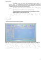
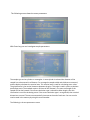
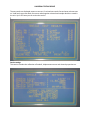
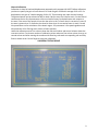
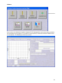
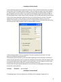
OPERATIONAL MANUAL
UTM-4000
UNIVERSAL TEST MACHINE
EN 10002-1
BMS Bulut Makina Sanayi ve Ticaret Ltd. Şti.
İkitelli Organize Sanayi Bölgesi Dolapdere Sanayi Sitesi
Ada 4 No : 7-9 Başakşehir / İSTANBUL-TÜRKİYE
Phone : +90 212 671 02 24 / 671 02 25 Fax : +90 212 671 02 26
web : www.bulutmak.com e-mail : [email protected]
USER MANUAL
Index
Section
Page
1. Safety and Security Devices
3
2. Functions of the machine
3
3. Operating principles
3
4. General description
3
5. Assembly and installation requirements
3
6. Technical Details
4
7. Fault Finding
4
8. Mainteneance
5
9. BC100 Display
5
10. Running a test
8
11. Software
10
Notice No part of this document can be copied or reproduced without the prior
written permission of UTEST Material LTD.
2
1
Safety and Security Devices
Only qualified personnel must use this device since it has high voltage and high pressure.
It is very important that the user must read and understand this document before using
the device. The machine has 2 safety protections.
- Overload protection valve: The piston hydraulic does not go furthermore than 215 bar (by
cutoff valve). Therefore the loadcell is protected to exceed 600kN.
- Lower grip limit switches: The lower switch has to be adjusted such that two grips do not
touch to each other. The lower switch has to be positioned such that the upper grip can move
till the end of the frame. These switches reside in the bottom of the frame. The vertical
clearance between the grips are 360mm. These switches stop the movement of the lower grip
(stops the motor running with 220V controlled through jog)
2 Functions of the machine
The user can make tensile tests of steel rods between 8-40 mm and steel plates up to
75x30mm (with optional plate grips)
The compression tests up to 600 kN can be done with the suitable compression plates The
bending tests can also be implemented till 600kN with appropriate accessories.
3 Operating principles
The lower end of the steel rebar sample is placed in lower grippers and the upper end in
upper grippers and the system pumps oil to the piston so that the upper gripper moves
upward and make a tensile test. Similarly for compression test you can place the sample
between the compression plates and with the same logic the machine does compression
test on the upper part of the machine.
4 General description
- Machine frame, loadcell, piston assembly ,hydraulic unit.
Piston assembly mounted on the top of the rigid frame. The loadcell resides on the piston.
Mobile frame consist of four high tensile strength columns. The upper crosshead is
housing the lower crosshead. The upper crosshead connected to the piston. Vertical
daylight is continuously adjustable up to 360mm
Hydraulically operated opening of grippers and electromechanically adjustment of vertical
clearance. Two cylinders are controlled by the pedal that adjusts the pressure for grips.
- Grippers
Two sets of grippers supplied with the machine for tensile tests of round and flat
(Optional) specimen. - Safety features
Pressure switch automatically stops the pressure on maximum permissible pressure of 215 bar
- Control console
It includes Hydraulic pump, selenoid valves, two motors, oil tank, motor inverter, and power supply
and display unit. The display unit does the signal conditioning of loadcell and displacement sensor
and gives the voltage regarding to the speed of the test. It also transmits values to the computer and
receives command from the computer.
5 Assembly and installation requirements
- Foundations
It is advisable to start the foundation work prior to the arrival of the machine.
Check also if there is any problem about transportation. If it is the case inform us such that the
person coming for installation is prepared for the problem.
- Arrival of the machine
3
The machine comes with oil tank is full. If there exists leakage you can use number 37 hydraulic oil
in order to complete it. - Erection of the machine
Unpack the package and screw the machine to the ground. Use spirit level in order to make the
alignment correct. - Assembly
Put the control console near 30-40cm of the frame. Connect all cables (They have all labels on the
control console and wires.)
The electrical connections are the following:
Loadcell, LVDT, RS232 (Computer), Pedal (these are to the hydraulic unit)
Lower Grip Remote Jog Panel
The oil connections are as
Piston, Upper grip, Lower grip
- Preliminary checks
1. Check the available voltage, 220V monophase is required with at least 10 Amper.
2. Plug 220V and push to the buttons of remote jog. The lower crosshead must move respect up or
down.
3. Take the air of cylinders of lower and upper (if necessary) by taking the switch to the LOAD
position from the control console. When the oil comes, tighten the connection.
4. Check the oil level. You can see the oil level when you open the backside of the control console.
5. In case it is necessary to add oil, use number 37 oil.
7 Fault Finding
- Excessive noise of the pump
Indicates that oil is missing. If the noise continues check suction filter, it might be
dirtied. Noise coming from the grips It might be due to a lack of lubrication. Grease the grips
jaw faces.
- The motor does not regulate the loading speed.
For compression tests (For slow pace rate values servo machine has to be used, the
best performance is achieved at 5kN/sec for compression tests.) For tensile tests 5mm/min40mm/min can be used. There might be problem at the inverter (Omron) if all parameters are
correct. - Slipping of specimen Excessive wear of gripping systems. You have to replace
Gripping jaw not suitable to dimensions. Select the suitable set.
4
8 Maintenance
- Periodically clean the tension and compression testing spaces. In
particular, clean
The gripping jaws and take off parts falling from the specimen
during the tensile test. Clean the jaw faces with a solvent, bearing in mind that the
gripping parts have to be greased with a graphite grease.
- Periodically grease the points of the hydaulic control of the gripping
system.
- Check the oil level and refill if necessary with Telius 37 oil.
- Check the alignment of the machine by means of adjustment of screws.
- Replace hydraulic oil after 300 hours of use.
- If you see fluctuations on the load curve you might have to replace jaw
faces - Replace the relays/contactors of control console after 500 hours of use.
9 Display Unit
The main screen of the tensile test is as follows.
While test is running you see instantaneous load stress and strain values. Those values are
frozen when the test is completed and the state of the machine is written as HOLD. On that
point the yield load and yield stress is calculated and displayed on the left of the screen. You
have to press Tare key in order to get the piston to its home position and to free the frozen
values. Many parameters of the test can be achieved by Menu key. You have to be in STOP
state in order to reach menu parameters.
5
The following screen shows the menu parameters.
With Enter key you can investigate sample parameters.
The sample type can be cylinder or rectangular. In case cylinder is selected the diameter of the
sample has to be entered in millimeters. For rectangular samples width and thickness are entered,
and the display calculates the nominal area. This nominal area is used for calculating stress value.
The grip distance is the vertical clearance between the grips. This value is used in order to calculate
percentage strain (The standard requires 10 times of the diameter). The mass and length of the
sample can be also entered. If the stress calculation type is selected as Mass Length, then this
information is used for calculating stress. If the stress calculation type is as registered, then nominal
dimensions are used. The test no automatically increases at the end of each test. You can see the
results saved in the memory by using this record number.
The following is the test parameters screen.
6
If the control mode is selected as Manual the speed of the machine is controlled through the
potentiometer on the console. For automatic selection machine uses the value in the speed area.
Select max. Available load depends of the capacity of the machine (such as 400kN or 600kN). The
failure threshold has to be selected as 1kN. The machine begins to search if there is a drop at load
after 1kN.
Fail Detection % is for defining the percentage drop from peak. For rebars %50 or %60 can be used.
If this value is selected less as 10%, the machine stops prior to break the rebar after a 10% drop from
the peak.
Zero suppression can be set as 0kN. The machine displays zero till passing this value. It has not
function like to tare the load value.
Yield Shift value can be selected as 0.2. If the extensometer is not used and yield point is calculated
below than expected, choose it 0.3.
Stress calculation type can be selected as register or mass-length. When registered is selected, the
stress value is calculated using the nominal values of the sample. When mass-length is selected then
it calculates the area using the density of steel.
The speed of the machine can be selected between 5-40mm/min. Optimal tests are achieved at
1015mm/min.
Max Graph stress is used in drawing the graph. 750 is meaningful for displaying graph better.
Max Graph Strain can be selected as 25%.
Do not forget to save your parameters.
TestResults
7
UNIVERSAL TESTING DEVICE
The test results are displayed respect to test no. Go to load test results line and enter relevant test
no. Yield load, stress max load, max stress and elongation at break and sample details are saved in
the unit. Up to 255 tests you can review the results.
Device settings
This section includes the calibration of loadcell, displacement sensor and channel properties etc.
Channel Calibration
Calibration is done for load and displacement separately with password of 11057. Before calibration
you have to specify the gain of each channel. For load use gain of 360 with average of 16 or 32. For
displacement use gain of 1 with averaging of 16 or 32. These settings are under channel settings.
The decimal points can be selected as 2dp for load, 0 dp for stress and 1 dp for strain. On the control
coefficients section first 6 parameters are the correction factors for displacement with respect to
the area. If the area of the sample is less than the value in the 7th factor then 1st correction is used. If
the area is greater than 7th factor but less than 8th factor then 2nd correction factor is used. 13th and
14th parameters are for calculation of the elastic region. 15th parameter is for speed regulation and
16th parameter is for filtering strain values at failure position.
Under the calibration menu first column shows the real world values and second column shows the
raw count values. First choose number of calibration points and enter first column values, then go to
second column and after starting the machine with Start key, take each corresponding raw count by
Enter or down arrow. Do not forget to save your calibration.
UNIVERSAL TESTING DEVICE
9
Software
If you want to use software at another computer for file management, go to setup screen and select
file management only property. If you want to control machine, choose the relevant COMPort from
the setup menu. The following is tensile test screen.
10
UNIVERSAL TESTING DEVICE
As you notice the test key of the software is not active. Click on the File key and select a new file for
making tests. Each file includes twenty samples in order to display the graphs and results together.
On each file when you click sample no, the diameter and grip distance automatically changes. (It
goes as 8,8,8,10,10,10,12,12,12,etc.) If you enter mass and whole length of the rebar you will see
the calculated diameter of the rebar also. After selecting a file, the setup and test keys will be active.
If you are sure about parameters about the setup, you can go to directly on the test. The setup
parameters are saved on a file, therefore you do not need to change each time you run the
software. The following are setup parameters. You can adjust the axis values after the test also but
test speed and the other parameters have only affected before the test.
The first three parameter is for axis adjustment. They do not affect the test results. The other
parameter is about the speed of the test.
The calculation of the yield point in fact done after completing the test. Generally 0.2 yield that is
common by the Standard is used. The digital unit calculates the yield point itself and software itself,
therefore small differences might appear on these calculations. You can change this number later
and calculate yield value by clicking on calculate yield again button also.
You can select the type of graph displayed also. You can switch on these graphs by using the right
mouse click on the graph also
UTM-4000
EN 10002-1
Rev. 3 / 27 April
UNIVERSAL TESTING DEVICE
The language page is for report purposes or switching to other languages. (Logo,title etc.)
11