1
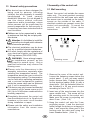
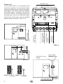
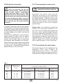
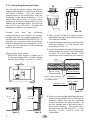
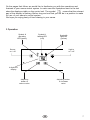
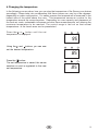
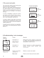
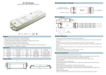
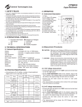
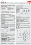
Installation and user's manual
ECON A1
GB
IP x4
GB
29343277en / - 43.06
1
Contents
1
1.1
1.2
1.3
General information
Technical Data
Package contents
General safety precautions
2
Assembly of the control unit
2.1 Wall mounting
2.2 Electrical connection
2.2.1 Connecting the sauna oven
2.2.2 Connecting the sauna lamp
2.3 Connecting the sensor lines
3
3.1
Operation
Using the sauna
4
Changing the temperature
5
Control unit switch
6
Troubleshooting
7
Circuit diagram
8
Terms of guarantee
1 General information
1.1
Technical data
ated voltage:
400 V 3 N 50 Hz AC
Breaking capacity:
max 9 kW resistive load (AC 1 operation) upgrade to 36 kW
possible through connection to circuit breakers
Heating time shut-off:
Heating time limit: 6 h
Display:
Protection type:
two-digit, 7 segmented display
IPx4 in accordance with DIN (German Standards Institution)
40050, Splashproofing
Control range, sauna operation: 40 to 115° C
Sensor system:
KTY sensor with safety temperature limiter 139°C
Type of regulation:
Digital two-point control
Light:
max. 200 W max. 1A
Environmental temperature -10°C bis +40°C
Storage temperatures:
-20°C bis +70°C
1.2 Package contents
(subject to change)
Included with the control unit are
1. an oven-sensor board with overheat shutoff protection, KTY-sensors with sensor housing,
two 3x25 mm fastening screws and a 1,7 m long sensor cable.
2. a plastic bag with three 4 x 20 mm fastening screws and three spacer tubes
3. a replacement overheat protection module
2
GB
1.3 General safety precautions
2 Assembly of the control unit
lThis device has not been designed for
being used by persons (including
children) that are physically or mentally
handicapped or have sensory
disabilities. Moreover, it is not allowed to
use this device without sufficient
experience and/or knowledge, unless
these persons will be supervised by
persons responsible for their security or
in case they have been instructed how to
use this device.
2.1 Wall mounting
Mount the control unit outside the sauna
cabin only. The most practical mounting
point would be the wall area onto which
the sauna oven is mounted on the inside,
except on the outside of the cabin. If
electrical conduits are present, mount the
control unit accordingly. To mount the
control unit, please follow these
instructions:
lChildren are to be supervised in order
to make sure that they do not play with
this device.
l
Attention: It is forbidden to install the
control box in a closed switch cabinet or
behind a wooden panelling!
l The electrical installation may be done
only by a qualified electrical technician.
l You must comply with the regulations of
your electrical supplier and applicable
VDE regulations (DIN VDE 0100).
l
WARNING: Never attempt repairs
or installations yourself, as this
could result in serious injury. Only a
qualified technician may remove the
housing cover.
l Please note the dimensions in the
assembly instructions, especially when
installing the temperature sensor. The
temperature above the oven is critical for
the temperature setting. The temperature
can be held within operating parameters
and a minimal temperature gradient
inside the sauna cabin can be achieved
only if unit is assembled correctly.
l The device may only be used as intended
as a control unit for sauna ovens up to 9
kW. (Up to 36 kW when combined with a
breaking capacitor).
l Completely disconnect the control unit
from the electrical circuit, i.e. flip all circuit
breakers or the main circuit breaker
during installation or repair.
l Please note the safety and installation
information from the sauna oven
manufacturer.
Fastening screws
Illust. 1
1. Remove the cover of the control unit.
Loosen the fastening screws below the
control panel. If your unit uses control
knobs, remove them. Enlarge the holes
for the electrical cables (Illust. 4) with a
sharp knife. Drill the threaded holes for
the included 4 x 20 mm wood screws
according to Illust.s 3 & 3.1.
2. Insert one of the wood screws into the
upper middle hole. This screw will be
the mounting point for the control unit.
Make sure the screw is projecting out
about 3 mm. (Illust. 3.2)
3. Hang the control unit onto the 3 mm
projecting screw. Lead the electrical
cable through the holes you enlarged in
step 1 and screw the lower part of the
housing onto the cabin wall using the
lower threaded holes. (Illust. 4)
GB
3
threaded holes
Please note:
upper threaded hole
If the sauna cabin is not equipped with
electrical conduits, the electrical cables
must be lead along the outside of the cabin,
preferably in one of the recesses between
the wood boards. Therefore, you have to
mount the control unit farther away from
the cabin wall, so you can lead the cables
into the unit. In this case, use the included
spacer tubes as shown in Illust. 3.3
lead hole for
sensor lines
lead hole for lamp,
ventilator
Illust. 3
lead hole for power
supply lead wire
lead hole for
oven connector
eye level
ca. 20 cm
Illust. 4
15 cm
ca. 34 cm
eye level
20 cm
Lead wire for cabin
lighting
Power supply
lead wire
Illust. 3.1
Illust. 3.2
3
Illust. 3.3
3
Air intake opening
4
GB
Illust. 5
2.2 Electrical connection
2.2.1 Connecting the sauna oven
The electrical connection can
only be carried out by an
approved electrician, observing the
local energy supply company's
guidelines and those of the VDE
(German Electrical Association). We
should advise you at this point that in
the case of a warranty claim, a copy of
the invoice from the electrical company
who carried out the work will be
required.
Warning: Always connect the
sauna oven's neutral conductor.
Assemble the sauna oven and the
vaporizer according to the instructions
provided by the manufacturer in front of the
air intake opening. Lead the silicon lines
and electrical conduits to their respective
terminals on the control unit and connect
them according to the circuit diagram
printed there.
In general, there can only be one permanent connection to the power supply network,
to include a device which allows the unit to
be disconnected from the power source with
a contact distance of at least 3 mm from all
terminals.
All electrical installations and connector
cables inside the cabin must be able to
withstand temperatures up to 140°C.
Please use the table below to determine
the required cable diameters for this task.
Attach the power supply lead wire as shown
in Illust. 5 to the power supply terminals of
the control unit. Connection instructions are
printed directly in the control unit.
Please note: If no electrical conduits are
present, drill a hole with a diameter of 10
mm next to the air intake opening and lead
the oven control cables through this hole
to their corresponding terminals (U V W) in
the control unit. To protect the silicon lines
from external influences, install them in a
shielded fashion. For this task, use a fitting
cable or simple PVC conduit and lead the
silicon cable through it to the control unit
2.2.3 Connecting the sauna lamp
The sauna lamp must be splashproof (by
Standard IP54) and suitable for
temperatures up to 140°C. The sauna
lamp can be mounted anywhere except in
the area of the rising hot air above the oven.
.
Tab. 1
connector
capacity in
KW
appropriate for
cabin sizes
in m³
minimum diameter in mm² (copper wire)
connection to 380 V 3N AC
power supply lead wire
to the control unit
oven connector cable
control unit for oven
safety fuse
capacity in A
4,5
4 - 6
5 x 2,5 mm²
5 x 1,5 mm²
3 x 16
6,0
6 - 10
5 x 2,5 mm²
5 x 1,5 mm²
3 x 16
7,5
8 - 12
5 x 2,5 mm²
5 x 1,5 mm²
3 x 16
9,0
10 - 14
5 x 2,5 mm²
5 x 1,5 mm²
3 x 16
GB
5
sensor
board
Ô
2.3 Connecting the sensor lines
red
red
white (Limiterf)
housing
white (Limiter)
Sensor
You should not install sensor and power
supply lines together, or lead them through
the same conduit. This can lead to
interferences in the electronics, such as
"fluttering" in the switch protectors. If it is
absolutely necessary to install them
together, or the wire is longer than 3m, you
should use a shielded sensor line such as
the LIYLY-O (4 x 05, mm²). Connect the
shielding to mass in the control unit.
Illust. 10
Please note that the following
measurements are based on values
provided by the unit quality assurance by
the European Standard EN 60335-53-2. In
principle, you must mount the oven sensor
where temperatures are the highest. Illust.
7 gives you an overview of the mounting
point of the sensor.
2. Drill a hole to lead the cable through,
preferably through the middle of one of
the wooden boards.
3. Lead the sensor cable through the drilled
hole and attach it to the sensor line
according to Illust. 11.
4. Attach the lines for the shutoff (white) and
the temperature sensor (red) according
to Illust. 10 to the sensor board. Then
insert the sensor board into the housing.
Mounting the oven sensor
1. Mount the oven sensor in cabins up to
2 x 2m according to Illust. 7 and 8, in larger
cabins according to Illust.s 7 and 9.
hole
20
sauna ceiling
center sensor housing
on middle section
Illust.
terminals in the
control unit
sensor housing
sensor line
sensor shutoff
Illust. 11
35 cm
19 cm
Illust. 8
6
5. After you are finished installing and have
made sure the control unit is functioning
properly, check the line for overheat
shutoff protection for short circuits. To
do this, release one of the white lines in
the sensor housing. The control unit's
safety relay should now fall, i.e. the
heating circuit should now be
interrupted.
Illust. 9
GB
On the pages that follow, we would like to familiarise you with the operations and
features of your sauna control system. In each case the illustrations next to the text
means that the relevant
show the displays visible on the control unit. The symbol
part of the display is flashing. Before long we trust that you will be in a position to make
full use of your sauna’s control system.
We hope you enjoy plenty of time relaxing in your sauna.
3 Operation
Symbol &
operating
LED (green)
Symbol &
heating LED
(red)
Sauna
on / off
Symbol &
light LED
(yellow)
Light o
on / off
4-digit LED
display
Adjusting button
to increase
value
Adjusting
button to
reduce value
GB
7
3.1 Using the sauna
Press the
button to switch on the sauna
heater. The display shows the the set
temperature (factory setting 95° C). The
green operating LED comes on and as
long as the sauna heater is on, the red
heating LED is also displayed.
95
Switch off the sauna
At expiration of the heating time delimitation
the plant switches off automatically. If you
want to switch the plant off manually, press
the
- button. When switching off the
control reacts mode of operation-
Switching the light on and off
By pressing the
button, the sauna room
lighting can be switched on or off. The yellow
light LED is also illuminated on the display
when the lighting is switched on.
8
95
GB
4 Changing the temperature
In the following one we show, how you can stop the temperature of the Sauna your desires
accordingly. Please take into consideration that these values can vary by a few degrees,
depending on cabin configuration. For safety reasons the temperature is measured in the
hottest area of the cabin above the oven. This temperature serves as a value for the
temperature around the sauna benches. Depending on oven capacity and placement of
the fresh air vents, undesirable influences can alter these measurements, not allowing the
maximum temperature to be reached. The control range is laid out so that normal
temperatures in the bench area can be preselected.
Press the
or
button until the set
temperature is displayed.
95
Using the and buttons, you can now
set the desired temperature.
85
Press the
button..
The set temperature is saved, the sauna
switches on and is regulated to the new
set temperature.
85
GB
9
5 The control unit switch
The control unit switch can be found on the
top end of the unit. Using this
switch, you can isolate the electronics from
the mains supply in case of a breakdown.
Please note that operating the control unit
switch returns all settings to the factory
settings.
Control unit switch
= unit
switched
on
In case of breakdown, press the control
unit switch on the left part of the rocker to
the first position (switch position 0). The
unit is now completely switched off.
= unit
switched
off
In order to switch on the light in the sauna
when the unit is switched off, press on the
left part of the rocker to the second position
(switch position II).
= light
switched
on
In order to put the unit back into operation,
switch back to the starting position (switch
position I).
6 Troubleshooting / error messages
Display /
symptom
E
E
Unit not working
Display dark
10
Cause
Remedy
Interruption or
short circuit in
sensor circuit
Check KTY sensor (approx. 2 kÙ at 20°
C). Check wire (red) and connections for
interruption or short circuit.
Interruption in
limiter circuit
Check continuity on safety temperature
limiter. Check wires (white) and
connections
Control unit switch
switched off
Switch on control unit switch
Mains fault
Check on-site fuses and main switch
GB
7 Connection diagram
Attention!
Dear customer,
according to the valid regulations, the
electrical connection of the sauna heater
and the control box has to be carried
out through the specialist of an
authorized electric shop.
We would like to mention to the fact that
in case of a warrenty claim, you are
kindly requested to present a copy of
the invoice of the executive electric
shop.
GB
11
Guarantee
The guarantee is taken over according to
the legal regulations at present.
Manufacturer’s warrenty
- The period of warrenty starts from the
date of purchase and lasts up to 2 years
for commercial use and 3 years for private use.
- Always include the completed warrenty
certificate when returning equipment.
- The warrenty expires for appliances
which have been modified without
manufacturer’s explicit agreement.
- Damages caused by incorrect operation
or handling through non-authorized
persons are not covered under the
terms of warranty.
- In the event of a claim, please indicate
the serial number as well as the article
code number and type name with expressive description of the fault.
- This warrenty covers damaged parts but
no defects due to wear and tear.
In case of complaint please return the
equipment in its original packaging or
other suitable packaging (caution: danger
of transport damage) to our service
department.
Always include the completed warrenty
certificate when returning equipment.
Possible shipping costs arising from the
transport to and from point of repair cannot
be borne by us.
Outside of Germany please contact your
specialist dealer in case of warranty claims.
Direct warranty processing with our service
department is in this case not possible.
Service Address:
EOS-Werke Günther GmbH
Adolf-Weiß-Str. 43
35759 Driedorf-Germany
tel +49 (0)2775 82-240
fax +49 (0)2775 82-455
[email protected]
www.eos-werke.de
12
Equipment start-up date:
Stamp and signature of the authorized
electrician:
GB