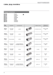
1
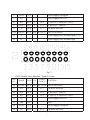
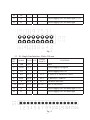
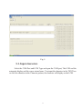
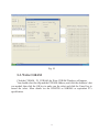
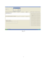
145 Royal Crest Court Unit 42 Markham, ON, Canada L3R 9Z4
Tel: 905-477-1166 Fax: 905-477-1782 http://www.orientdisplay.com
User Manual
CUSTOMER
CUSTOMER PART NO.
PART NO.
AMCT-1
DESCRIPTION
APPROVED BY
DATE
PREPARED BY
2008-10-20
CHECKED BY
1
APPROVED BY
TABLE OF CONTENTS
1 General Specification
.....................................................
2 Main Components On The AMCT-1
3 Interface For LCM
4
General Operation
5
PC Software Operation
3
.............................
3
…….................................................
4
…….....................…………...........
8
……..............................................
9
APPENDIX
Specification Revision History
..……………………………
2
15
1.
General Specification
The Character LCD Module Evaluation & Development Board (AMCT-1) has
been designed for evaluating Character LCD modules without having to lay out your
own PCB and design your software. It provides pinouts for the most popular modules in
the industry. It will interface to most modules that use the industry-standard HD44780
controller (or equivalent), running in 8-bit or 4-bit mode(software select).
The AMCT-1 uses an Atmel AT89C4051 processor to control the LCM and
communication with the PC by RS232C . The custom can easy use yourself processor to
driver the LCM whit yourself progress.
2 . Main Components On AMCT-1
Main components in the AMCT-1
NO. Symbol
Name
Supply
FUNCTION
1
/
Power
Interface
2
/
Power Supply Switch Turn on and turn off the Power Supply
3
LED
Power Light (red)
+5VDC(+/-5%) Power Supply for the board
It be light when Power Supply be turned on
4
Current Current Test Jump
Open it and connect to a multimeter to test the
LCM current
5
KEY2
Press it once the LCM display a character in COM
port not be connected
6
J5
BL Power
Jump
7
J6
External
Power
External Power Supply For Back Light, +5VDC
Supply For Back Light
8
J15
Back Light Power
Select pin15 of D1 connect to A or K
Polarity Select
9
J16
Back Light Power
Select pin15 of D1 connect to A or K
Polarity Select
10
11
Step Key
Supply Short it when using internal power for back light,
Open it when using in external power for back light
RS232C RS232 Interface
Trimmer Resistor
Connect to PC COM port with cable
Adjust the contrast of the LCM
3
Fig. 1
3. Interface For LCM
There are different interface for different LCM. These allow most LCD modules
that use an HD44780 compatible controller to be connected directly. Of course,
non-standard pinouts can always be wired in using ribbon cable.
3.1 D1: Double Lines Interface , Pitch=2.54 mm
PIN
NO.
Symbol
Level
I/O
1
VSS
0V
/
Connect
To MCU
FUNCTION
GND
4
2
VDD
+5 V
/
Power Supply for logical
3
V0
/
Power Supply for LCD
4
RS
H/L
I
P3.5
H: DATA, L: INSTRUCTION
5
R/W
H/L
I
P3.3
H: READ, L: WRITE
6
E
H/L
I
P3.7
ENABLE SIGNAL
7-14
D0-D7
H/L
15
A
/
/
Power Supply for LED back light (+5V)
16
K
/
/
Power Supply for LED back light
I/O P1.0-P1.7 DATA SIGNALS
Fig. 2
3.2 D2: Double Lines Interface , Pitch=2.54 mm
PIN
NO.
Symbol
Level
Connec
To MCU
1-8
D7-D0
H/L I/O
9
E1
H/L
I
P3.7
ENABLE SIGNAL
10
R/W
H/L
I
P3.3
H: READ, L: WRITE
11
RS
H/L
I
P3.5
H: DATA, L: INSTRUCTION
12
V0
13
VSS
14
15
I/O
FUNCTION
P1.7-P1.0 DATA SIGNALS
/
Power Supply for LCD
0V
/
GND
VDD
+5 V
/
Power Supply for logical
E2
H/L
I
P3.2
ENABLE SIGNAL
5
16
NC
17
A
/
/
Power Supply for LED back light (+5V)
18
K
/
/
Power Supply for LED back light
Fig. 3
3.3 S1: Single Line Interface , Pitch=2.54 mm
PIN
NO.
Symbol
Level
I/O
Connect
To MCU
1
VSS
0V
/
GND
2
VDD
+5 V
/
Power Supply for logical
3
V0
/
Power Supply for LCD
4
RS
H/L
I
P3.5
H: DATA, L: INSTRUCTION
5
R/W
H/L
I
P3.3
H: READ, L: WRITE
6
E
H/L
I
P3.7
ENABLE SIGNAL
7-14
D0-D7
H/L
15
A
/
/
Power Supply for LED back light (+5V)
16
K
/
/
Power Supply for LED back light
FUNCTION
I/O P1.0-P1.7 DATA SIGNALS
Fig. 4
6
3.4 S2: Single Line Interface , Pitch=2.54 mm
PIN
NO.
Symbol
Level
I/O
Connect
To MCU
16
K
/
/
Power Supply for LED back light
15
A
/
/
Power Supply for LED back light
1
VSS
0V
/
GND
2
VDD
+5 V
/
Power Supply for logical
3
V0
/
Power Supply for LCD
4
RS
H/L
I
P3.5
H: DATA, L: INSTRUCTION
5
R/W
H/L
I
P3.3
H: READ, L: WRITE
6
E
H/L
I
P3.7
ENABLE SIGNAL
7-14
D0-D7
H/L
FUNCTION
I/O P1.0-P1.7 DATA SIGNALS
Fig. 5
3.5 SS1: Single Line Interface , Pitch=1.27 mm
PIN
NO.
Symbol
Level
I/O
Connect
To MCU
1
VSS
0V
/
GND
2
VDD
+5 V
/
Power Supply for logical
3
V0
/
Power Supply for LCD
4
RS
H/L
I
P3.5
H: DATA, L: INSTRUCTION
5
R/W
H/L
I
P3.3
H: READ, L: WRITE
6
E
H/L
I
P3.7
ENABLE SIGNAL
7-14
D0-D7
H/L
15
A
/
FUNCTION
I/O P1.0-P1.7 DATA SIGNALS
/
Power Supply for LED back light
7
16
K
/
/
Power Supply for LED back light
Fig. 6
8
4 . General Operation
Plug your LCM in correct interface and make sure that the J15 and J16 be in
correct position for back light power supply. Connect the RS232C cable to a PC COM
port while both the AMCT-1 and the PC be off.
Turn on the AMCT-1 power supply and adjust the trimmer resistor to get a
good contrast. The LCM display the character one by one automatic, the default LCM
type is 20*2 .
Fig. 7
When you press the step key, the display just add one character once press.
9
Fig. 8
5. PC Software Operation
The PC software is working for Windows 2000 or Windows XP. Copy the
SNDclcm.rar to you computer and unzip it. Running the SNDclcm.exe, it will appear as
follow.
10
Fig. 9
5-1. Input characters
Select the COM Port and LCM Type and open the COM port, The LCM end the
automatic display and the cursor return home. You input the character in the TEXT box
or click the character in the Character pattern, the character will display on the LCM.
11
Fig. 9
5-2. LCM Function Set
Click the LCM Set – Function Set, the LCM Function Set Windows will appear,
there are 4 functions set.
(1) Entry Mode Set ;
(2) Display ON/OFF Control ;
(3) Cursor or Display Shift ;
(4) Function.
You can change the select by click the function, and click the OK key to make
sure the select and click the Cancel key to cancel the select. More details see the
HD44780 or S6B0069 or equivalent IC’s specification.
12
Fig. 10
5-3. Write CGRAM
Click the CGRAM – W_CGRAM, the Write CGRAM Windows will appear.
You should select the chip and the CGRAM Address, and click the character’s dot
you needed, then click the OK key to make sure the select and click the Cancel key to
cancel the select. More details see the HD44780 or S6B0069 or equivalent IC’s
specification.
13
Fig. 11
5-4. COM_TEST
If the communication is not good, Click the COM_TEST – COM_TEST, the
COM_TEST Windows will appear.
If the communication is good, the numbers is add by one automatic, click OK
key to exit. If not good, it will appear a window indicate: “ Please Check the Connect”.
14
Fig. 12
15
REVISION HISTORY
Rev
1.0
Content
Initial Version
Date
2008-10-20
16