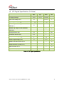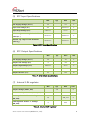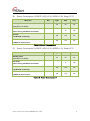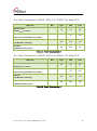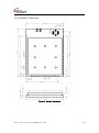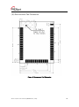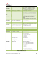
1
WizFi210/220 User Manual (Version 1.11) ©2011 WIZnet Co., Ltd. All Rights Reserved. ☞ For more information, visit our website at http://www.wiznet.co.kr WizFi210/220 User Manual (WIZnet Co., Ltd.) Certification Information CE for Class B ITE INFORMATION TO THE USER Hereby, WIZnet. Declares that these WizFi210 and WizFi220 are in compliance with the essential requirements and other relevant provisions of directive 1999/5/EC. WARNING: These are the class B products. In a domestic environment this product may cause radio interference in which case the user may be required to take adequate measures. FCC for Class B ITE INFORMATION TO THE USER These equipments have been tested and found to comply with the limits for a Class B digital device, pursuant to part 15 of the FCC Rules. These limits are designed to provide reasonable protection against harmful interference in a residential installation. This equipment generates, uses and can radiate radio frequency energy and, if not installed and used in accordance with the instructions, may cause harmful interference to radio communications. However, there is no Guarantee that interference will not occur in a particular installation. If this equipment does cause harmful interference to radio or television reception, which can be determined by turning the equipment off and on, the user is encouraged to try to correct the interference by one more of the following measures: Reorient or relocate the receiving antenna. Increase the separation between the equipment and receiver. Connect the equipment into an outlet on a circuit different from that to which the receiver is connected. - Consult the dealer or an experienced radio/TV technician for help. WARNING: These equipments may generate or use radio frequency energy. Changes or modifications to this equipment may cause harmful interference unless the modifications are expressly approved in the instruction manual. The user could lose the authority to operate this equipment if an unauthorized change or modification is made. KC for Class B ITE INFORMATION TO THE USER This equipment has been tested for a Class B digital device. - Trade Name or Applicant : WIZnet, Co., Ltd. - Equipment Name : Wireless LAN Module - Model Number : WizFi210 / WizFi220 - Manufacturer / Country of Origin : WIZnet, Co., Ltd. / KOREA - Certification Number : KCC-CRM-WWW-WIZFI210 / KCC-CRM-WWW-WIZFI220 WARNING: This equipment may generate or use radio frequency energy. Changes or modifications to this equipment may cause harmful interference. WizFi210/220 User Manual (WIZnet Co., Ltd.) Document Revision History Date Revision 2011-03-24 V1.0 Official Release V1.01 Changed Power Consumption and RF Output Power Added Auto Reconnect AT Command(AT+XAR) Added Certification Information V1.10 Changed Evaluation Board Changed GPIO number(HW Trigger, Button) Changed AT+XEHT Command Added Limited AP Feature Added WizFi220 Specs V1.11 Added Added Added Added Added 2011-05-24 2011-09-05 2012-01-11 Changes UART baud rate(460800, 921600) EXT_RESET description FAQ AT+DHCPSRVR Command Product contents WizFi210/220 User Manual (WIZnet Co., Ltd.) <Contents> 1. 2. 3. 4. 5. 6. Overview .......................................................................................................................... 1 (1) Benefits and Features ............................................................................................... 2 (2) Specifications ............................................................................................................ 3 (3) Product contents (WizFi2x0-EVB) .............................................................................. 3 Hardware Specification .................................................................................................... 4 (1) Operating Conditions ............................................................................................... 4 (2) Digital Input Specifications ....................................................................................... 4 (3) Digital Output Specifications .................................................................................... 4 (4) I/O Digital Specification (Tri-State)............................................................................ 5 (5) RTC Input Specifications ........................................................................................... 6 (6) RTC Output Specifications ........................................................................................ 6 (7) Internal 1.8V regulator .............................................................................................. 6 (8) Power Consumption (VDDRTC=VDD=3.3V, VDDIO=1.8V, Temp=25°C) ..................... 7 (9) Power Consumption (VDDRTC=VDD=3.3V, VDDIO=3.3V, Temp=25°C) ..................... 7 (10) Power Consumption (VDDRTC=VDD=3.3V, VDDIO=1.8V, Temp=25°C)............... 8 (11) Power Consumption (VDDRTC=VDD=3.3V, VDDIO=3.3V, Temp=25°C)............... 8 (12) RF Specification .................................................................................................. 9 (13) Block Diagram .................................................................................................. 10 (14) Pin Description ................................................................................................. 11 (15) Module Dimension ........................................................................................... 15 (16) Recommend Pad Dimension............................................................................. 16 (17) LED Indications ................................................................................................. 17 (18) Application Circuit ............................................................................................ 18 (19) Interface ........................................................................................................... 19 (20) Using EXT_RESET pin ........................................................................................ 20 Application Guide .......................................................................................................... 21 (1) AP Scanning ........................................................................................................... 21 (2) Network Connection Management ......................................................................... 21 (3) Auto Connection Operation.................................................................................... 21 (4) Response Codes ..................................................................................................... 23 (5) Use of GPIO21 ........................................................................................................ 24 (6) AT Command example ........................................................................................... 24 AT Commands ............................................................................................................... 26 (1) Command interface ................................................................................................ 26 (2) UART / adapter interface configuration .................................................................. 26 (3) Profile management ............................................................................................... 27 (4) Wi-Fi interface ........................................................................................................ 28 (5) Wi-Fi security .......................................................................................................... 29 (6) Wireless configuration ............................................................................................ 30 (7) Network interface ................................................................................................... 30 (8) Connection management ....................................................................................... 31 (9) Battery check .......................................................................................................... 32 (10) Power state management ................................................................................. 32 (11) Auto connection ............................................................................................... 33 (12) Provisioning ...................................................................................................... 33 (13) Miscellaneous ................................................................................................... 33 FAQ ................................................................................................................................ 35 Warranty ........................................................................................................................ 38 WizFi210/220 User Manual (WIZnet Co., Ltd.) <Table> TABLE 1. SPECIFICATIONS ...................................................................................................................................... 3 TABLE 2. OPERATING CONDITIONS ................................................................................................................... 4 TABLE 3. DIGITAL INPUT SPECIFICATIONS .................................................................................................... 4 TABLE 4. DIGITAL OUTPUT SPECIFICATIONS ............................................................................................... 4 TABLE 5. I/O DIGITAL SPECIFICATION ............................................................................................................... 5 TABLE 6. RTC INPUT SPECIFICATIONS ............................................................................................................ 6 TABLE 7. RTC OUTPUT SPECIFICATIONS ....................................................................................................... 6 TABLE 8. INTERNAL 1.8V REGULATOR ............................................................................................................. 6 TABLE 9. POWER CONSUMPTION 1 ................................................................................................................... 7 TABLE 10. POWER CONSUMPTION 2 ................................................................................................................ 7 TABLE 11. POWER CONSUMPTION 3 ................................................................................................................. 8 TABLE 12. POWER CONSUMPTION 4 ................................................................................................................ 8 TABLE 13. RF SPECIFICATION ............................................................................................................................... 9 TABLE 11. PIN DESCRIPTION............................................................................................................................... 14 TABLE 15. LED INDICATIONS ............................................................................................................................... 17 TABLE 13. RESPONSE CODES ........................................................................................................................... 23 TABLE 14. AT COMMAND EXAMPLE ................................................................................................................. 25 TABLE 15. COMMAND INTERFACE ................................................................................................................... 26 TABLE 16. UART / ADAPTER INTERFACE CONFIGURATION .............................................................. 27 TABLE 17. PROFILE MANAGEMENT................................................................................................................. 27 TABLE 18. WI-FI INTERFACE ................................................................................................................................ 29 TABLE 19. WI-FI SECURITY ................................................................................................................................... 30 TABLE 20. WIRELESS CONFIGURATION ....................................................................................................... 30 TABLE 21. NETWORK INTERFACE .................................................................................................................... 31 TABLE 22. CONNECTION MANAGEMENT ..................................................................................................... 32 TABLE 23. BATTERY CHECK ................................................................................................................................ 32 TABLE 24. POWER STATE MANAGEMENT ................................................................................................... 33 TABLE 25. AUTO CONNECTION .......................................................................................................................... 33 TABLE 26. PROVISIONING ..................................................................................................................................... 33 TABLE 27. MISCELLANEOUS ............................................................................................................................... 34 WizFi210/220 User Manual (WIZnet Co., Ltd.) <Figure> FIGURE 1. BASIC DIAGRAM .................................................................................................................................... 1 FIGURE 2. WIZFI210 BLOCK DIAGRAM .......................................................................................................... 10 FIGURE 3. WIZFI220 BLOCK DIAGRAM .......................................................................................................... 10 FIGURE 4. PIN DESCRIPTION.............................................................................................................................. 11 FIGURE 5. MODULE DIMENSION ....................................................................................................................... 15 FIGURE 6. RECOMMEND PAD DIMENSION ................................................................................................. 16 FIGURE 7. VIN = BATTERY, STANDBY MODE SUPPORT ........................................................................ 18 FIGURE 8. VIN = DC ADAPTOR, ALWAYS ACTIVE ...................................................................................... 18 FIGURE 9. WIZFI2Z0 EVB INTERFACE ............................................................................................................ 19 FIGURE 10. USING EXT_RESET PIN ................................................................................................................ 20 FIGURE 11. FACTORY DEFAULT AND AD HOC MODE ............................................................................ 24 WizFi210/220 User Manual (WIZnet Co., Ltd.) 1. Overview The WizFi210 family of fully certified modules offers a quick, easy, and cost effective way for device and appliance manufacturers to add Wi-Fi capabilities to their products. The module provides serial UART interface which enables connection to any embedded design utilizing an 8/16/32-bit microcontroller via simple commands. The WizFi210 is an ideal solution for organizations with limited or no Wi-Fi or RF expertise, as it not only dramatically reduces RF design time but also removes the burden of testing and certification; allowing customers to focus on their core application, product, or expertise. The module supports data rates up to 11 Mbps, and is compliant with 802.11b. The WizFi210 provides customers the mean to evaluate the capabilities of ultra-low power wireless system-on-a-chip and the Serial to Wi-Fi embedded software for Wi-Fi networks. The Serial to Wi-Fi embedded software allows devices and appliance manufacturers to easily add Wi-Fi capabilities to their products with minor impact on the host microcontroller firmware. The WizFi210 provides all the hardware and software necessary to quickly set up a serial (UART) based link to a PC or external microcontroller. The WizFi220 is a RF-enhanced Product. Except for [RF Output Power], the WizFi220 is similar in management and development to the WizFi210. In other words, the WizFi220 will consume more power but it has the improved WiFi range. (All documents for the WizFi210 apply to the WizFi220) Figure 1. Basic Diagram WizFi 210/220 User Manual (WIZnet Co., Ltd.) 1 (1) Benefits and Features Brings Wi-Fi connectivity to any device with a microcontroller and serial HOST interface (UART) Minimal Serial to Wi-Fi “driver” footprint on host microcontroller and minor changes to existing host MCU firmware Offloading of smaller host microcontrollers from the Wi-Fi and TCP/ IP networking Simple AT commands for configuration and data communication DHCP/Static IP, TCP/UDP, Server/Client, DNS Reduces development time, testing and certification burden, accelerating time to market Easy device provisioning through our utility or Wi-Fi Protected Set-up (WPS) Ultra low power consumption through dynamic power management Operates with standard 802.11 b/g/n access points at speed up to 11 Mbps (802.11b) 802.11i Security (WEP, WPA, WPA2-PSK, Enterprise) Rich I/O interfaces (SPI, UART, GPIO, I2C, ADC, JTAG) Low power modes, Alarm Input for wake-up High-throughput hardware AES and RC4 encryption/decryption engines Limited AP Feature (Direct Connection to iPhone, iPad and Android-Phone without AP) WizFi 210/220 User Manual (WIZnet Co., Ltd.) 2 (2) Specifications Specifications Description Radio Protocol IEEE 802.11b/g/n Compatible Supported Data Rates 11, 5.5, 2, 1 Mbps (802.11 b) Modulation DSSS and CCK RF Operating Frequency 2.4 - 2.497 GHz Antenna Options Chip antenna and U.FL connector for external antenna Networking Protocols Power Consumption (Typical) RF Output Power (Typical) Security Protocols UDP, TCP/IP (IPv4), DHCP, ARP, DNS, HTTP/HTTPS Client and Server(*) Standby = 34.0 µA(WizFi210), 35.0 µA(WizFi220) Receive = 125.0 mA(WizFi210), 125.0 mA(WizFi220) Transmit = 135.0 mA(WizFi210), 250.0 mA(WizFi220) 8 ± 1 dBm (WizFi210) 17 ± 1.5 dBm (WizFi220) WEP, WPA/WPA2–PSK, Enterprise, EAP-FAST, EAP-TLS, EAPTTLS, PEAP I/O Interface UART, SPI(*), I2C(*), WAKE, ALARM, GPIOs Power Source 3.3V Dimensions 32 x 23.5 x 3 mm Table 1. Specifications (*) is supported by software customizing. (3) Product contents (WizFi2x0-EVB) WIZFi 2x0 Module + Interface Board + Base Board Serial Cable / 1EA USB Cable / 1EA Antenna(W5I-BO-07) / 1EA : for WizFi2x0-CO(connector) version WizFi 210/220 User Manual (WIZnet Co., Ltd.) 3 2. Hardware Specification (1) Operating Conditions Min Typ Max Unit +85 °C Operating Ambient Range -40 RTC Supply Voltage 1.2 3.3 3.6 V Single Supply Voltage 3.0 3.3 3.6 V Table 2. Operating Conditions (2) Digital Input Specifications IO Supply Voltage Min Typ Max Unit 1.62/3 1.8/3.3 1.98/3.63 V Input Low Voltage (VIL) -0.3 0.25VDDIO V Input High Voltage (VIH) 0.8VDDIO VDDIO V Schmitt trig. Low to High threshold point (VT+) 1.5 V Schmitt trig. High to Low threshold point (VT-) 1 V Table 3. Digital Input Specifications (3) Digital Output Specifications IO Supply Voltage Min Typ Max Unit 1.62/3 1.8/3.3 1.98/3.63 V Output Low Voltage (VIL) 0 0.4 V Output High Voltage (VIH) 1.3 VDDIO V Output rise time (tTLH) 7 ns Output fall time (tTHL) 7 ns Table 4. Digital Output Specifications WizFi 210/220 User Manual (WIZnet Co., Ltd.) 4 (4) I/O Digital Specification (Tri-State) IO Supply Voltage Min Typ Max 1.62/3 1.8/3.3 1.98/3.63 Unit Input Low Voltage (VIL) -0.3 0.25VDDIO V Input High Voltage (VIH) 0.8VDDIO VDDIO V Schmitt trig. Low to High threshold point (VT+) 1.5 Schmitt trig. High to Low threshold point (VT-) V 1 V Pull-Up Resistor (Ru) 0.05 1 MΩ Pull-Down Resistor (Rd) 0.05 1 V Output Low Voltage (VOL) 0 0.4 V Output High Voltage (VOH) 1.3 VDDIO V Output rise time @ 3.3V (tToLH) 7 ns Output fall time @ 3.3V (tToHL) 7 ns Input rise time (tTiLH) 7 ns Input fall time (tTiHL) 7 ns Table 5. I/O Digital Specification WizFi 210/220 User Manual (WIZnet Co., Ltd.) 5 (5) RTC Input Specifications Min Typ Max Unit RTC Supply Voltage (VDDRTC) 1.2 3.6 V Input Low Voltage (VIL) -0.3 0.25VDDRTC V Input High Voltage (VIH) 0.8VDDRTC VDDRTC V 0.57VDDRTC 0.68VDDRTC V 0.27VDDRTC 0.35VDDRTC V Max Unit 1.2 3.6 V Output Low Voltage (VOL) 0 0.4 V Output High Voltage (VOH) 0.8VDDRTC VDDRTC V Output rise time (tTLH) 19 142 ns Output fall time (tTHL) 21 195 ns Max Unit Schmitt trig. Low to High threshold point (VT+) Schmitt trig. High to Low threshold point (VT-) Table 6. RTC Input Specifications (6) RTC Output Specifications Min RTC Supply Voltage (VDDRTC) Typ Table 7. RTC Output Specifications (7) Internal 1.8V regulator Min Typ Output Voltage (VOUT_1V8) 1.8 Maximum Output Current (IVOUT_1V8) 250 1.8V Regulator Enable "H" Voltage (EN_1V8) 1.8V Regulator Enable "L" Voltage (EN_1V8) V 300 mA 1.0 VIN_3V3 V 0 0.25 V Table 8. Internal 1.8V regulator WizFi 210/220 User Manual (WIZnet Co., Ltd.) 6 (8) Power Consumption (VDDRTC=VDD=3.3V, VDDIO=1.8V, Temp=25°C) WizFi 210 Min Type Max Unit 35 50 µA 10 mA 125 130 mA 135 140 mA Standby mode (Only VDDRTC is active) Idle mode (CPU running, WLAN disconnected) Receive (-81dBm RX sensitivity) Transmit (+8dBm at antenna port) Table 9. Power Consumption 1 (9) Power Consumption (VDDRTC=VDD=3.3V, VDDIO=3.3V, Temp=25°C) WizFi 210 Min Standby mode (Only VDDRTC is active) Type Max Unit 35 50 µA 11 mA 125 130 mA 135 140 mA Idle mode (CPU running, WLAN disconnected) Receive (-81dBm RX sensitivity) Transmit (+8dBm at antenna port) Table 10. Power Consumption 2 WizFi 210/220 User Manual (WIZnet Co., Ltd.) 7 (10) Power Consumption (VDDRTC=VDD=3.3V, VDDIO=1.8V, Temp=25°C) WizFi 220 Min Standby mode (Only VDDRTC is active) Type Max Unit 35 50 µA 12 mA 125 130 mA 250 260 mA Idle mode (CPU running, WLAN disconnected) Receive (-81dBm RX sensitivity) Transmit (+8dBm at antenna port) Table 11. Power Consumption 3 (11) Power Consumption (VDDRTC=VDD=3.3V, VDDIO=3.3V, Temp=25°C) WizFi 220 Min Standby mode (Only VDDRTC is active) Type Max Unit 35 50 µA 13 mA 125 130 mA 250 260 mA Idle mode (CPU running, WLAN disconnected) Receive (-81dBm RX sensitivity) Transmit (+8dBm at antenna port) Table 12. Power Consumption 4 WizFi 210/220 User Manual (WIZnet Co., Ltd.) 8 (12) RF Specification Specification Modulation Technique Data Rate Description DSSS for 1, 2Mbps CCK for 5.5, 11Mbps IEEE 802.11b: 1, 2, 5.5 and 11Mbps -84dBm ± 1dB @ 11Mbps Receive Sensitivity(*) -88dBm ± 1dB @ 5.5Mbps -90dBm ± 1dB @ 2Mbps -94dBm ± 1dB @ 1Mbps Transmit power(*) (Average) WizFi 210 : 8dBm ± 1dB @ 11Mbps WizFi 220 : 17dBm ± 1.5dB @ 11Mbps USA: 2.400 ~ 2.483GHz Frequency Range Europe: 2.400 ~ 2.483GHz Japan: 2.400 ~ 2.497GHz China: 2.400 ~ 2.483GHz USA/Canada: 11 (1~11) Major Europe Countries: 13 (1~13) Operating Channels France: 4 (10~13) Japan: 14 for IEEE 802.11b (1~13 or 14th), 13 for IEEE 802.11g (1~13) Korea/China: 13 (1~13) U.FL External Antenna Support(CON) Antenna External Antenna Pad Support(EX) Chip Antenna (Optional) (CA) Table 133. RF Specification (*) applies to only WizFi2x0-CON(U.FL Connector version) WizFi 210/220 User Manual (WIZnet Co., Ltd.) 9 (13) Block Diagram Figure 2. WizFi210 Block Diagram Figure 3. WizFi220 Block Diagram WizFi 210/220 User Manual (WIZnet Co., Ltd.) 10 (14) Pin Description TOP VIEW 19 20 21 22 23 24 25 26 27 28 29 30 1 2 3 4 5 6 7 8 9 10 11 12 13 14 15 16 17 18 EXT-ANT 48 47 46 45 44 43 42 41 40 39 38 37 36 35 34 33 32 31 GND GPIO28 GPIO29 GPIO30 GPIO31 UART0_CTS/GPIO24 UART0_RX/GPIO0 UART0_RTS/GPIO25 UART0_TX/GPIO1 UART1_TX/GPIO2 UART1_RX/GPIO3 UART1_RTS/GPIO27 UART1_CTS/GPIO26 EXT_RESETN VDDIO EN_1V8 VIN_3V3 GND MSPI_CS0/GPIO4 MSPI_CS1/GPIO13 I2C_CLK/GPIO9 PWM0/GPIO10 GPIO19/CLK_44MHz GPIO20/CLK_22MHz GPIO21/CLK_11MHz I2C_DATA/GPIO8 SSPI_MISO SSPI_CLK SSPI_CS SSPI_MOSI GND JTAG_TCK JTAG_TDO JTAG_TDI JTAG_TMS JTAG_NTRST ALARM1 RTC_OUT1 VBAT DC_DC_CNTL ALARM2 ADC1 ADC2 MSPI_MISO/GPIO6 MSPI_MOSI/GPIO7 MSPI_CLK/GPIO5 VOUT_1V8 GND 49 Figure 4. Pin description WizFi 210/220 User Manual (WIZnet Co., Ltd.) 11 PIN NAME I/ O IN BIAS DESCRIPTION 1 GND P NA Ground 2 JTAG_TCK (*) I Pull-up Joint Test Action Group Test Clock 3 JTAG_TDO (*) O NA Joint Test Action Group Test Data Out 4 JTAG_TDI (*) I NA 5 JTAG_TMS (*) I Pull-up 6 JTAG_NTRST (*) I Pull-up 7 ALARM1 I NA 8 RTC_OUT1 (*) O NA 9 VBAT P NA Embedded Real Time Clock Power Supply 10 DC_DC_CNTL O NA VIN_3V3 Regulator Control Output 11 ALARM2 (*) I NA 12 ADC1 (*) I NA General Analog to Digital Converter 1 13 ADC2 (*) I NA General Analog to Digital Converter 2 14 MSPI_MISO/GPIO 6 (*) I Pull-down 15 MSPI_MOSI/GPIO 7 (*) O Pull-down 16 MSPI_CLK/GPIO5 (*) O Pull-down 17 VOUT_1V8 (*) P NA Internal 1.8V Vout 18 GND P NA Ground 19 MSPI_CS0/GPIO4 (*) O Pull-down 20 MSPI_CS1/GPIO13 (*) O Pull-down WizFi 210/220 User Manual (WIZnet Co., Ltd.) Joint Test Action Group Test Data In It should not be left floating Joint Test Action Group Test Mode Select Joint Test Action Group Test Mode Reset Active Low Embedded Real Time Clock Wake Up Input 1 Embedded Real Time Clock Wake Up Output 1 Embedded Real Time Clock Wake Up Input 2 Master Serial Peripheral Interface Bus Data Input / General Purpose Input Output Master Serial Peripheral Interface Bus Data Output / General Purpose Input Output Master Serial Peripheral Interface Bus Clock / General Purpose Input Output Master Serial Peripheral Interface Bus Chip Select 0 / General Purpose Input Output Master Serial Peripheral Interface Bus Chip Select 1 / General Purpose Input Output 12 Inter-Integrated Circuit Clock / General 21 I2C_CLK/GPIO9 (*) IO Pull-down 22 PWM0/GPIO10 O Pull-down 23 GPIO19/CLK_44M Hz (*) I Pull-down 24 GPIO20/CLK_22M Hz (*) I Pull-down 25 GPIO21/CLK_11M Hz (*) I Pull-down 26 I2C_DATA/GPIO8 (*) IO Pull-down 27 SSPI_MISO (*) O Pull-up 28 SSPI_CLK (*) I Pull-up SPI Slave Clock Input from the HOST 29 SSPI_CS (*) I Pull-up SPI Slave Chip Select Input from the HOST 30 SSPI_MOSI (*) I Pull-down 31 GND P NA Ground 32 VIN_3V3 P NA Single Supply Port 33 EN_1V8 I NA 34 VDDIO(**) P NA 35 EXT_RESETN IO Pull-up 36 UART1_CTS/GPIO 26 (*) Purpose Input Output Pulse Width Modulator / General Purpose Input Out-put Internal Clock Circuitry Test Point / General Purpose Input Output Internal Clock Circuitry Test Point / General Purpose Input Output Internal Clock Circuitry Test Point / General Purpose Input Output Inter-Integrated Circuit Data / General Purpose Input Output SPI Slave Transmit Data Output to the HOST SPI Slave Receive Data Input from the HOST Internal 1.8V regulator enable port-Active High All I/O voltage domain (can be tied to VIN_3V3 or tied to HOST I/O supply) Module Hardware Reset Input and Power Supply Reset Monitor Indictor Universal Asynchronous Receiver I Pull-down Transmitter 1 Clear to Send Input / General Purpose Input Output Universal Asynchronous Receiver Transmitter 1 Request to Send Output / 37 UART1_RTS/GPIO2 7 O Pull-down General Purpose Input Out-put / Firmware Program Mode It support download mode at high during boot WizFi 210/220 User Manual (WIZnet Co., Ltd.) 13 38 UART1_RX/GPIO3 (*) Universal Asynchronous Receiver I Pull-down Transmitter 1 Receive Input / General Purpose Input Output 39 UART1_TX/GPIO2 (*) Universal Asynchronous Receiver O Pull-down Transmitter 1 Transmitter Output / General Purpose Input Output Universal Asynchronous Receiver 40 UART0_TX/GPIO1 O Pull-down Transmitter 0 Transmitter Output / General Purpose Input Output 41 UART0_RTS/GPIO2 5 Universal Asynchronous Receiver O Pull-down Transmitter 0 Request to Send Output / General Purpose Input Out-put Universal Asynchronous Receiver 42 UART0_RX/GPIO0 I Pull-down Transmitter 0 Receive Input / General Purpose Input Output 43 UART0_CTS/GPIO 24 Universal Asynchronous Receiver I Pull-down Transmitter 0 Clear to Send Input / General Purpose Input Output 44 GPIO31 IO Pull-down General Purpose Input Output 45 GPIO30 IO Pull-down General Purpose Input Output 46 GPIO29 IO Pull-down General Purpose Input Output 47 GPIO28 IO Pull-down General Purpose Input Output 48 GND P NA Ground 49 EXT-ANT IO NA External Antenna pad Table 14. Pin description (*) is not available in this version. (**) To allow for design flexibility and support for multiple sensors with different voltages, the VDDIO banks are split, such that some of the VDDIO banks can be 1.8 V and some can be 3.3 V. If a VDDIO bank is connected to 1.8 V then the corresponding I/O signals for that bank should be driven at the same voltage. VDDIO Bank 1 : GPIO28~29, JTAG, VDDIO Bank 2 : SPI1(Master), Misc VDDIO Bank 3 : GPIO18~23, PWM VDDIO Bank 4 : I2C, SPI2(Slave), GPIO16~17 VDDIO Bank 5 : UART0~1 VDDIO Bank 6 : GPIO30~31 WizFi 210/220 User Manual (WIZnet Co., Ltd.) 14 (15) Module Dimension Figure 5. Module dimension WizFi 210/220 User Manual (WIZnet Co., Ltd.) 15 (16) Recommend Pad Dimension Figure 6. Recommend Pad Dimension WizFi 210/220 User Manual (WIZnet Co., Ltd.) 16 (17) LED Indications Condition D3(PWR) D1(GPIO 30) D2(GPIO 31) D4 (GPIO 28) ON Solid Power On - Serial-To-WiFi OK Associated Blink(-1-) - Blink(-1-1-) - OFF No Power Serial Data Rx - (Data Mode) Serial Data Rx - - Serial-To-WiFi Error Not Associated (AT Command Mode) - Table 155. LED Indications WizFi 210/220 User Manual (WIZnet Co., Ltd.) 17 (18) Application Circuit Figure 7. VIN = Battery, Standby mode support Figure 8. VIN = DC Adaptor, Always active [GPIO29] is used for mode transition between data/command mode. And [GPIO21] is used for factory default and <Limited AP Configuration Mode>self test. So, this should be considered, except in special cases In order to upgrade the firmware of the WizFi210, the hardware design to transit between run mode and program mode is required as shown as above. WizFi 210/220 User Manual (WIZnet Co., Ltd.) 18 (19) Interface RS232C Power Connector DC-Jack Wake-up 5V Input Alarm Button Switch Chip Antenna WizFi2x0 Module Mini USB 5V Input Reset Button Function Button Command/Data Run/Program Mode Switch Mode Switch (GPIO 21) Figure 9. WizFi2z0 EVB Interface WizFi 210/220 User Manual (WIZnet Co., Ltd.) 19 (20) Using EXT_RESET pin EXT_RESET pin is bidirectional. EXT_RESET pin is an output right at power-on, and kept it asserted while the 32KHz crystal is stabilizing. Once crystal is stabilized, RESET is de-assert and it becomes an input. Also at power up, WizFi210 don't require a reset, as it have a power-on-reset already built in. So MCU need not assert unless there is a real issue (E.g. hang). Note: Minimum pulse width for reset is two 32KHz clock. Figure 10. Using EXT_RESET pin EXT_RESET signal is active low signal (active or asserted state occurs when the signal is at a low voltage level). Be sure that <Led Blink during boot> is not progressed, if WizFi210 is reset by EXT_RESET. WizFi 210/220 User Manual (WIZnet Co., Ltd.) 20 3. Application Guide (1) AP Scanning The Serial2WiFi interface can instruct the Wi-Fi radio to scan for access points and ad hoc networks with a specified SSID, BSSID and/or channel for a specified scan time. Scanning can be performed to find networks with a specific SSID, BSSID, networks operating on a specific radio channel, or a combination of these constraints. (2) Network Connection Management The connection management module is responsible for processing connection-related events. The interface provides UDP and TCP sockets (similar to the familiar BSD network sockets). Each socket may represent either a server or client connection. Each such connection has a unique, single-digit hexadecimal value (0 to 15) for the CID. The allowed maximum number of connections (up to 16) may be specified at compile time. Note that this single pool of CID‟s is used for TCP, UDP, Server and Client connections (3) Auto Connection Operation Auto Connection acts as a cable replacement insofar that the interface acts like a serial interface and no commands or user intervention are required for connection management. In this mode, the Station automatically builds the wireless and network connections by using parameter values from the current active Profile, then transfers data transparently between the Host and Target in data mode. No status information is sent to the Host. The operation modes of WizFi210 are as below Command Mode : in which data is interpreted as commands to control WizFi210 Data Mode : in which serial data is sent to the WiFi interface In Data mode the Adapter: ► Receives characters from the serial port and transmits them over the connection ► Receives data from the connection and transmits it on the serial port The serial host may gain control of the interface by issuing the escape sequence “+++”, followed by a one-second gap where no characters are received on the serial port. When this sequence is encountered, the Adapter exits data mode and resumes command processing. The host then makes changes in the network configuration or other parameters WizFi 210/220 User Manual (WIZnet Co., Ltd.) 21 as needed. However, the Adapter does not accept any new TCP/UDP client/server or data connection requests. The ATO command (terminated by the ASCII character “O”, not the number 0) is used to return to data mode. Applying the <AT+XEHT> command (Enable Hardware Trigger), you can change between data mode and command mode using GPIO 29, without escape sequence (“+++”). But it should be noted that GPIO number is different depending on the firmware version. AT+XEHT=2,1,0,3 (HW Trigger-GPIO29, ButtonAction-GPIO21) AT+XEHT=1,0,0,1 (HW Trigger-GPIO10, ButtonAction-GPIO10) (in old EVB) But when you use GPIO29(GPIO10) for data/command mode transition, there should be no UART input in 300mS before and after sending signal to GPIO29(GPIO10) for mode transition time and buffer processing time. Using D2(GPIO 31), D4(GPIO 28) of WizFi210, you can see if the WizFi210 is associated to the AP and if serial-to-wifi network channel is normal. And applying the “AT+XDUM=1” command (Disable UART Message), all UART messages are blocked in data mode. In this situation, you have to check the signal of GPIO 28 and GPIO 31 to know disassociation or network connection closed. In data mode, the Nagle Algorithm Wait Time can be used to buffer any characters to be sent, in order to avoid sending a large number of packets with small payloads onto the network. The wait time is specified in units of 10 milliseconds. This functionality is available for both UDP and TCP connections. WizFi 210/220 User Manual (WIZnet Co., Ltd.) 22 (4) Response Codes The possible responses sent by the Adapter to the serial host are described below. The Response Codes can be distinguished into codes resulting from the AT Command or not. There are Carriage Return(\r, 0x0d) and Line Feed(\n, 0x0a) above and below ASCII STRING. If you send “at” string and Line Feed to the WizFi210, at + Line Feed (0x61 0x74 0x0d) You can see the following data. at + Carriage Return (0x61 0x74 0x0d) + \r\n[OK]\r\n (0x0d 0x0a 0x5b 0x4f 0x4b 0x5d 0x0d 0x0a) No ASCII CHAR 1 Response ASCII STRING Meaning 0 S2W_SUCCESS [OK] Command Request Success. 2 1 S2W_FAILURE [ERROR] Command Request Failed. 3 2 S2W_EINVAL [ERROR: INVALID INPUT] Invalid Command or Option or Parameter. 4 3 S2W_SOCK_FAIL [ERROR: SOCKET FAILURE] Socket Operation Failed. 5 4 S2W_ENOCID [ERROR: NO CID] All allowed CID’s in use, so there was no CID to assign to the new connection. 6 5 S2W_EBADCID [ERROR: INVALID CID] Invalid Connection Identifier. 7 6 S2W_ENOTSUP [ERROR: NOT SUPPORTED] Operation or Feature not supported. 8 7 S2W_CON_SUCCESS [CONNECT <CID> <info>] TCP/IP connection successful. <CID> = the new CID in hexadecimal format. 9 8 S2W_ECIDCLOSE [DISCONNECT <CID>] TCP/IP connection with the given CID is closed. This response is sent to the host when a connection is closed either by the remote device or by the serial host. 10 9 S2W_LINK_LOST [DISASSOCIATED] Not associated to a wireless network. 11 A S2W_DISASSO_EVT [Disassociation Event] Wireless network association lost. Table 16. Response Codes WizFi 210/220 User Manual (WIZnet Co., Ltd.) 23 (5) Use of GPIO21 If you click the GPIO21(GPIO10) button twice consecutively, the WizFi210 is restored to factory default and changed <Limited AP mode>. Depending on the firmware version, you can configure WizFi210’s WiFi setting using the web browser. (IP:192.168.1.1/Subnet:255.255.255.0/Gateway:192.168.1.1, URL : http://192.168.1.1) And if you click the GPIO21(GPIO10) button three times consecutively, the WizFi210 is restored to factory default and will change to ad hoc mode to configure the WizFi210 via WiFi. (IP:192.168.1.254/Subnet:255.255.255.0/Gateway:192.168.1.1) Figure 11. Factory Default and ad hoc mode As previously described, GPIO10 is used for data/command mode transition by applying “AT+XEHT=1” command. But there should be no UART input in 300mS before and after sending signal to GPIO10 for mode transition time and buffer processing time. (6) AT Command example AT Command examples are described below. In this sample application, the WizFi210 associate to the AP and open the serial-to-wifi channel automatically after reboot. Description of each command is in the next chapter. No 1 2 3 MCU → WizFi210 WizFi210 → MCU (AT Command) (Echo and Result String) AT+WD AT+WD Description Disassociate [OK] AT+WWPA=12345678 AT+WWPA=12345678 Set WPA passphrase [OK] AT+NDHCP=1 AT+NDHCP=1 WizFi 210/220 User Manual (WIZnet Co., Ltd.) Enable DHCP 24 [OK] 4 5 6 7 8 9 10 AT+WAUTO=0,WizFiAP,,0 AT+WAUTO=0,WizFiAP,,0 Set WiFi Configuration [OK] AT+NAUTO=1,1,,4000 AT+NAUTO=1,1,,4000 TCP Server Mode(4000) [OK] ATC1 AT+XEHT=0,0,0,1 ATC1 [OK] Auto Connect on next reboot AT+XEHT=0,0,0,1 Disable Hardware Trigger [OK] AT+XDUM=1 AT&Y0 AT+XDUM=1 Disable UART Message [OK] AT&Y0 Set Default Profile [OK] AT&W0 AT&W0 Save Profile [OK] Table 17. AT Command Example WizFi 210/220 User Manual (WIZnet Co., Ltd.) 25 4. AT Commands This section provides a list of Serial2WiFi commands and their effects. Parameters are generally ASCII characters, e.g. ATEn with n=1 is the series of ASCII characters ‘A’, ‘T’, ‘E’, and ‘1’. Where some parameters are optional, mandatory parameters are denoted by < > and optional parameters by [ ]. If a parameter is mandatory, any associated sub-parameters are also mandatory; sub-parameters of an optional parameter are optional. Parameters must always be provided in the order given in the command description. When an optional parameter is not supplied, the comma delimiters must still be included in the command. Every command starts with the characters “AT”; any other initial characters will cause an error to be returned. Command Response: In most cases, valid commands return the characters OK. Invalid inputs return ERROR: INVALID INPUT. Some commands may be not supported depending on the version (1) Command interface Command Parameters Responses / Effects AT ATE “OK” n=0 (disable) =1 (enable) IF 1, echo all input. Ex) ATE0, ATE1 IF 1 responses are ASCII, else numerical ATV n=0 (disable) =1 (enable) codes. Ex) ATV0, ATV1 Table 18. Command interface (2) UART / adapter interface configuration Command Parameters Responses / Effects UART parameters are immediately reset to values provided.(9600, 19200, 38400, 57600, 115200, 230400, 460800, 921600) ATB <baudrate>[[,<bitsperchar>] [,<parity>][,<stopbits>]] Parity is n for no parity, e for even parity and o for odd parity. Allowed values are 5, 6, 7 or 8 bits/character, with 1 or 2 stop bits (1.5 in the case of a 5-bit character). Ex) ATB=9600,8,n,1 WizFi 210/220 User Manual (WIZnet Co., Ltd.) 26 AT&K n=0 (disable) =1 (enable) AT&R n=0 (disable) =1 (enable) IF 1, software flow control is enabled. Ex) AT&K0, AT&K1 IF 1, hardware flow control is enabled. Ex) AT&R0, AT&R1 Sets various timeout values; 0 (Network Connection Timeout, 10 milliseconds, 1~65535, default 1000) 1 (Auto Associate Timeout 10 milliseconds, 0~65535, default 500) 2 (TCP Connection Timeout ATS n=0 to 5; p=(parameter value) 10 milliseconds, 0~65535, default 500) 3 (Association Retry Count Not currently supported) 4 (Nagle Algorithm Wait Time 10 milliseconds, 0~65535, default 10) 5 (Scan Time 1 milliseconds, 0~65535, default 20) Ex) ATS0=1000, ATS1=500 Various Adapter ID information; 0 (OEM identification) ATI n=0 to 2; 1 (Hardware version) 2 (Software version) Ex) ATI0, ATI2 Table 19. Uart / adapter interface configuration (3) Profile management Command Parameters Responses / Effects AT&W n=0 (profile 0) =1 (profile 1) ATZ n=0 (profile 0) =1 (profile 1) AT&Y n=0 (profile 0) =1 (profile 1) AT&F Save profile specified by n. Ex) AT&W0 Load profile specified by n. Ex) ATZ0 Set default profile to the value n. AT&Y0 Restore profile to factory default values. Current and saved profile parameter values as AT&V ASCII. Table 20. Profile management WizFi 210/220 User Manual (WIZnet Co., Ltd.) 27 (4) Wi-Fi interface Command Parameters Responses / Effects Sets the adapter MAC address (an 8-byte AT+NMAC= <MAC Address> colon-delimited hexadecimal number), and stores the value in flash memory Sets the adapter MAC address (an 8-byte AT+NMAC2= <MAC Address> colon-delimited hexadecimal number), and stores the value in non-volatile RAM AT+NMAC=? Returns the current adapter MAC address. AT+NMAC=? Returns the current adapter MAC address. 0: FCC AT+WREGDO MAIN= : supported Channel range is 1 to 11. 1: ETSI : supported Channel range is 1 to 13. <Regulatory Domain> 2: TELEC : supported Channel range is 1 to 14. Ex) AT+WREGDOMAIN=? AT+WREGDOMAIN=2 Network scan, returns list of found networks in the format: AT+WS= [<SSID>[,<BSSID>][,<Channel>][,< <SSID>,<BSSID>,<Channel>,<RSSI>,<Mode>, Scan Time>]] <Security> Ex) AT+WS AT+WS=,,6 Set 802.11 Station operating mode. AT+WM= n=0 (infrastructure) =1 (ad hoc) =2 (limited AP) If n is 2, the mode is set to limited AP so that the adapter can act as a limited wireless Access Point. Ex) AT+WM=0 Associate to specified SSID, BSSID, and AT+WA= <SSID>[,[<BSSID>][,<Ch>]] channel. Ex)AT+WA=WizFiDemoAP AT+WD Disassociate from the current network. ATH Disassociate from the current network. Associate to an AP using WPS AT+WWPS= <METHOD>[,PIN] METHOD is push button (1) or pin (2). PIN is the pin for PIN method. AT+WWPS=2,12345670 AT+NSTAT=? Current wireless and network configuration. AT+WSTATUS Adapter reports the current network WizFi 210/220 User Manual (WIZnet Co., Ltd.) 28 configuration to the serial host AT+WRSSI=? Current RSSI as ASCII. AT+WRATE=? Current transmit rate as ASCII. AT+WRETRY= Value of 802.11 TX retry is reset. <retrycount> Ex) AT+WRETRY=5 Table 21. Wi-Fi interface (5) Wi-Fi security Command Parameters Responses / Effects Authentication mode setting; 0 : None AT+WAUTH= n=0 to 2 1 : Open 2 : Shared with WEP Ex) AT+WAUTH=0 WEP key n is set to the value in <key>. AT+WWEPn= n=1 to 4, <key> Ex) AT+WWEP1=123456abdc AT+WWEP3=abcdef12345678901234567890 WPA passphrase set to the value in AT+WWPA= <passphrase> <passphrase>. Ex) AT+WWPA=12345678 AT+WPAPSK= <SSID>,<passphrase> Computes and stores the WPA2 PSK value. Ex) AT+WPAPSK=WizFiDemoAP,12345678 Sets the WPA2 pre-shared key to the <PSK>. AT+WPSK= <PSK> Ex)AT+WPSK=00010203040506070809000102 03040506070809000102030405060708090001 Set the Outer authentication, Inner authentication, user name and password for EAP Security. This command returns the normal response codes. The valid outer authentication values are: AT+ WEAPCONF= <Outer Authentication>,<Inner Eap-FAST: 43 Authentication>,<user name>, Eap-TLS: 13 <password> Eap-TTLS: 21 Eap-PEAP: 25 The valid Inner Authentication values are: Eap-MSCHAP: 26 Eap-GTC: 6 Ex) AT+WEAPCONF=43,26,guest,1234 WizFi 210/220 User Manual (WIZnet Co., Ltd.) 29 Configure certificate for EAP-TLS Type: CA certificate(0)/ Client certificate(1)/ <Type>,<Format>,<Size>,<Locatio AT+WEAP= n> <ESC>W <data of size above> Private Key(2) Format: Binary(0)/Hex(1) Size: size of the file to be transferred. Location: Flash(0)/Ram(1) Ex) AT+WEAP=2,0,100,0 (cont.) <Esc>W<..data..> Table 22. Wi-Fi security (6) Wireless configuration Command Parameters AT+WRXACTIVE= n=0 (disable) =1 (enable) AT+WRXPS= n=0 (disable) =1 (enable) AT+MCSTSET= n=0 (disable) =1 (enable) If 1, multicast reception is enabled. <power> 0 to 7 (WizFi210) Transmit power set to <power>. AT+WP= 2 to 15 (WizFi220) AT+WSYNCINTRL= <n> 1 to 65535. AT+EXTPA= n=0 (disable) =1 (enable) AT+PSPOLLINTRL= <n> 1 to 65535. Responses / Effects If 1, 802.11 radio is enabled. Ex) AT+WRXACTIVE=1 If 1, Power Save mode is enabled. Ex) AT+WRXPS=1 Ex) AT+WP=0 Configure the sync loss interval Ex) AT+WSYNCINTRL=30 Enable/disable the external PA Ex) AT+EXTPA=0 Configure the keep-alive timer interval Ex) AT+PSPOLLINTRL=45 Table 23. Wireless configuration (7) Network interface Command Parameters Responses / Effects AT+NDHCP= n=0 (disable) =1 (enable) If 1, DHCP is enabled. AT+DHCPSRV R= n=0 (disable) =1 (enable) Prior to start the server, the adapter should be configured with a valid static ip address. Static network parameters; overrides previous AT+NSET= <Src Address>,<Net-mask>, <Gateway> values. Ex) AT+NSET=192.168.3.100,255.255.255.0,192.168 .3.1 AT+DNSLOOK <URL>,[<retry>,[<timeout=S>] WizFi 210/220 User Manual (WIZnet Co., Ltd.) Query DNS server for address of hostname 30 UP= URL. Ex) AT+DNSLOOKUP=google.com AT+DNSSET= <DNS1 IP>,[<DNS2 IP>] Set the DNS server addresses to be used. Ex) AT+DNSSET=192.168.3.1 AT+STORENW Store network connection parameters prior to CONN transition to Standby. AT+RESTOREN Restore network connection parameters after WCONN wake from Standby. Table 24. Network interface (8) Connection management Command Parameters Responses / Effects Attempt TCP client connection to Destination; AT+NCTCP= <Dest-Address>,<Port> CONNECT <CID> if successful. Ex) AT+NCTCP=192.168.3.200,5000 AT+NCUDP= <Dest-Address>,<Port> [<,Src.Port>] Open UDP client socket to Destination; CONNECT <CID> if successful. Ex) AT+NCUDP=192.168.3.200,5000 Start a TCP server on Port; CONNECT <CID> if AT+NSTCP= <Port> successful. Ex) AT+NSTCP=5000 UDP server on Port; CONNECT <CID> if AT+NSUDP= <Port> successful. Ex) AT+NSUDP=5000 AT+CID=? AT+NCLOSE= Returns the current CID configuration. <CID> AT+NCLOSEAL AT+SETSOCKO <Cid>,<Type>,<Parameter>,<Valu PT= e>,<Length> (*) AT+SSLCLOSE =(*) AT+HTTPCCO NF=(*) AT+HTTPCOPE Ex) AT+NCLOSE=1 Close all open connections. L AT+SSLOPEN= Close connection identified by CID. Configure a socket which is identified by a Cid <cid>,<certificate name> Open an SSL connection <cid> Close an SSL connection <Param>,<Value> Configure an HTTP client <host>,<Port Number>, [<SSL Open an HTTP client connection. This WizFi 210/220 User Manual (WIZnet Co., Ltd.) 31 N=(*) Flag>,<certificate name>] command opens an HTTP client on the adaptor and connects to the server specified by the host name or IP address AT+HTTPCSEN <cid>,<Type>,<Timeout>, GET/POST HTTP data on the HTTP client D=(*) <Page>,[Size of content] connection <cid> Close the HTTP client connection <0|1|2> Enable / Disable Raw Ethernet support. AT+HTTPCCLO SE=(*) AT+NRAW= <Frame Control>,<Sequence AT+UNSOLICIT Cntrl>,<Channel>,<Rate>,<WmmI EDTX= nfo>, <Receiver Mac>,<Bssid of Unsolicited data transmission AP>,<Frame Length> Table 25. Connection management (*) is about HTTP Client/SSL functions. If you want these functions, we can customize the WizFi210 firmware. (9) Battery check Command AT+BCHKSTRT = Parameters Responses / Effects Start checking battery <Batt.chk.freq> each 0 < Batt.chk.freq≤ 100 packets transmitted. AT+ <Warning Level>,<Warning BATTLVLSET= Freq>,<Standby Level> AT+BCHK= <Batt.chk.freq> Set the battery warning/standby level to enable the adaptor’s internal battery measuring logic Reset value of battery check frequency. AT+BCHKSTOP Stop checking battery. AT+BATTVALG Retrieve the most recent battery check value. ET Table 26. Battery check (10) Power state management Command Parameters AT+PSDPSLEE Responses / Effects Enable SOC Deep Sleep power saving mode. P Request transition to Standby for x AT+PSSTBY= <x>[,<DelayTime>,<Alarm1 milliseconds. pol.>,<Alarm2 pol.>] Ex) AT+PSSTBY=60000,1000,1,1 AT+PSSTBY=5000 WizFi 210/220 User Manual (WIZnet Co., Ltd.) 32 Table 27. Power state management (11) Auto connection Command Parameters Responses / Effects Sets WiFi parameters to be used for Auto Connect. AT+WAUTO= <mode>,<SSID>,[BSSID],[channel] Mode is 0 for Infrastructure and 1 for Ad-hoc mode Ex) AT+WAUTO=0,WizFiDemoAP Sets network parameters to be used for Auto Connect. Type is 0 for Client and 1 for Server; AT+NAUTO= <Type>,<Protocol>,<Destination IP>,<Destination Port> Protocol is 0 for UDP and 1 for TCP; Ex) AT+NAUTO=0,1,192.168.3.101,5000 (TCP/Client) AT+NAUTO=1,1, ,5001 (TCP/Server) AT+NAUTO=0,0,192.168.3.101,5002 (UDP, Local/Remote Port is 5002) ATC n=0 (disable) =1 (enable) IF 1, Auto Connect is enabled on next reboot or AT. ATA Start Auto Connect, including association. ATA2 Start Auto Connect using existing association. Return to a previous Auto Connect session; ATO AT+XAR= returns an error if no such session exists. n=0 (disable) Auto reconnect interval. 5 to 3600 (interval, seconds) Ex) AT+XAR=0, AT+XAR=10 Table 28. Auto connection (12) Provisioning Command Parameters Responses / Effects <user name>,<passwd> Provisioning through web pages AT+WEBLOGO <size> maximum size is 1788 Adding the Logo that will appear on the web ADD= bytes pages used for provisioning. AT+WEBPROV = Table 29. Provisioning (13) Miscellaneous Command Parameters WizFi 210/220 User Manual (WIZnet Co., Ltd.) Responses / Effects 33 AT+FWUP= AT+SETTIME= <SrvIp>,<SrvPort>,<SrcPort>,[<ret ry>] Get a firmware upgrade from the server address/port to the adapter port SrcPort. Ex) AT+FWUP=192.168.3.200,667,667 <dd/mm/yyyy>,<HH:MM:SS> Set the adaptor system time Upon reception of this command the adaptor sends the current system time in milliseconds since AT+ epoch(1970) to the serial interface. The time GETTIME=? format comes on the serial interface as follows: “Current Time in msec since epoch=xxxxxxx” AT+DGPIO= <GPIO-NO>,<SET/RESET(0/1)> AT+VER=? AT+PING= Set or reset (high/low) a GPIO pin Ex) AT+DGPIO=31,0 Return the current adapter firmware versions. <IP>,[[Trails],[<Interval>],[<Len>],[ <TOS>],[<TTL>],[<PAYLOAD>]] PING the IP address provided. Trails = 0 will ping until <Esc> C is issued. Ex) AT+PING=192.168.3.1,5 AT+TRACERO <IP>,[[Interval],[<MaxHops>],[<Mi Trace the route to the IP address provided. UTE= nHops>],[<TOS>]] Ex) AT+TRACEROUTE=74.125.155.103 AT+BDATA= n=1 (enable) =0 (enable) If 1, bulk data mode is enabled. AT+XDUM= n=1 (disable) =0 (enable) If 1, UART Message is Disabled.(When Auto Connection Mode) <HW Trigger GPIO> 0 (Disable HW Trigger) 1 (GPIO10) 2 (GPIO29) <HW Trigger GPIO>, AT+XEHT= <ActiveReverse> <ActiveReverse>, 0 (Change to Active Low) <SW Trigger Disable>, 1 (Change to Active High) <ButtonAction> <SW Trigger Disable> 0 (+++ Escape Sequence Enable) 1 (+++ Escape Sequence Disable) <ButtonAction> 1(GPIO10) 3(GPIO21) Ex) AT+XEHT=2,1,0,3 (Default) AT+XEHT=1,0,0,1 (in old EVB) Table 30. Miscellaneous WizFi 210/220 User Manual (WIZnet Co., Ltd.) 34 5. FAQ Q) The WizFi210 does not operate normally. When you connect power to WizFi210, the three LEDs are supposed to blink 3~4 times during booting. If the LEDs did not blink during boot-up, please check the below; - check if the <RUN/PROG Slide Switch> is at <RUN> - check the appropriate power level (in case of USB power, replace it with the dc adapter) Q) Serial of WizFi210 does not work. - check the serial cable and PC's serial port - verify the default serial configuration: 115200,8,n,1 - check if WizFi210 is in data mode (refer to the manual) Q) When I connect power to WizFi210, WizFi210 returns an "[ERROR]" string. What is the problem? There is no problem. After power on, WizFi210 would try to connect to a specific AP. That is the default setting. In short, WizFi210 boots within 100ms and tries to connect to a specific AP for 3~5 seconds. If that is failed, Wizfi210 returns an "[ERROR]" string. If you issue <ATC0> command, you can remove the <auto-connection option>. Q)WizFi210 cannot connect to the AP. - remove the authentication and encryption of the AP - check if another WiFi station is connected to the AP - check the AP option : 802.11b Enable, Hidden SSID WizFi 210/220 User Manual (WIZnet Co., Ltd.) 35 Q) When <AP dis-association> or <TCP Client disconnect> occurs, how can I get that notification? There are two ways. <Using serial message> If you issue <AT+XDUM=0> command, you can get the event message about <AP association/disassociation> and <TCP connect/disconnect> from serial. Of course, MCU should analyze the message and do proper reaction. <Using GPIO> You can check the status about <AP association/disassociation> and <TCP connect/disconnect> with LEDs of WizFi210-EVB. Q) What is the difference between WizFi210 and WizFi220? WizFi220 uses an external PA for higher RF output power. WizFi210 has the merit of low power consumption and WizFi220 has the merit of long-range feature. However, as regards of development and operation, there are no differences between WizFi210 and WizFi220 except one or two AT commands. Q) If I issue <AT+XEHT> command, an error occurs. Q) GPIO button does not work. There are two types of WizFi210-EVB. The above symptom can occur depending on the type of WizFi210-EVB and the firmware version. For details, please refer to the document [Using New Firmware version in Old EVB Type]. Q) What is the Limited AP? WizFi210 can do some limited AP functions. - 2~3 WiFi stations can be connected - cannot do L2 switching between WiFi stations - some WiFi authentication and encryption are not supported WizFi 210/220 User Manual (WIZnet Co., Ltd.) 36 Q) What is the max-throughput of Serial-to-WiFi? The default baud rate of WizFi210 is 115200bps, but you can change it to 921600bps with AT Command. However, you should consider using the hardware flow control in such high-baud-rate. If you set the baud rate to 921600bps and measure the throughput of Serial-to-WiFi and WiFi-to-Serial, you can get more than 500kbps in the effective rate, (transfers 1M file within 15 seconds) Q) When do I need to reset Wizfi210? If Wizfi210 does not return a [OK] string after sending the dummy <AT> command to WizFi210 in command mode, you need to reset WizFi210. There are two ways: Turning On/Off of main power of WizFi210 or Using the EXT_RESET pin. WizFi 210/220 User Manual (WIZnet Co., Ltd.) 37 6. Warranty WIZnet Co., Ltd offers the following limited warranties applicable only to the original purchaser. This offer is non-transferable. WIZnet warrants our products and its parts against defects in materials and workmanship under normal use for period of standard ONE(1) YEAR for the WizFi210/220 board and labor warranty after the date of original retail purchase. During this period, WIZnet will repair or replace a defective products or part free of charge. Warranty Conditions: 1. The warranty applies only to products distributed by WIZnet or our official distributors. 2. The warranty applies only to defects in material or workmanship as mentioned above in 3.Warranty. The warranty applies only to defects which occur during normal use and does not extend to damage to products or parts which results from alternation, repair, modification, faulty installation or service by anyone other than someone authorized by WIZnet Co., Ltd. ; damage to products or parts caused by accident, abuse, or misuse, poor maintenance, mishandling, misapplication, or used in violation of instructions furnished by us ; damage occurring in shipment or any damage caused by an act of God, such as lightening or line surge. Procedure for Obtaining Warranty Service 1. Contact an authorized distributors or dealer of WIZnet Co., Ltd. for obtaining an RMA (Return Merchandise Authorization) request form within the applicable warranty period. 2. Send the products to the distributors or dealers together with the completed RMA request form. All products returned for warranty must be carefully repackaged in the original packing materials. 3. Any service issue, please contact to [email protected] WizFi 210/220 User Manual (WIZnet Co., Ltd.) 38