1
Embedded Solutions
20G301-00 E4 – 2012-10-04
G301 – 3U CompactPCI®
Serial Unmanaged
4+1-Port Ethernet Switch
4-channel configuration with RJ45 connectors
User Manual
®
G301 – 3U CompactPCI® Serial Unmanaged 4-Port ETH Switch
G301 – 3U CompactPCI® Serial Unmanaged 4-Port ETH
Switch
The G301 is an unmanaged 3U Ethernet switch implemented as a CompactPCI®
Serial board. It occupies one peripheral slot, using a 4 HP front panel sporting
4 Gigabit Ethernet ports on RJ45 connectors. Options include M12 front connectors
and a P6 connector for the rear I/O Ethernet signals from the board's fifth Gigabit
Ethernet port.
The G301 supports full-duplex and half-duplex operation with auto-negotiation,
high-speed non-blocking store-and-forward switching, Quality of Service (QoS)
support with four traffic classes IEEE 802.1p and three-level 802.1x security. The
switch is fault tolerant and restores itself on its own: If a link is temporarily
unavailable, frames can be sent via backup/redundant links (spanning tree protocol /
link aggregation) and no data loss occurs. Its built-in test mechanisms make the
G301 an even more reliable component in the communication system.
In addition, the switch can act as Power over Ethernet (PoE) Power Sourcing
Equipment (PSE), supplying other devices on all ports with power.
By using an application-specific configuration EEPROM, the G301 can act
similarly to a managed switch with fixed settings. This enables features untypical
for unmanaged models like 802.1p priority and port based priority, port based
VLAN or IEEE 802.1q VLAN IDs.
The board is specifically designed for rugged mobile communication systems. It is
thus for example fully compliant with the EN 50155 railway standard, screened for
a -40 to +85×C operation temperature and ready for coating.
MEN Mikro Elektronik GmbH
20G301-00 E4 – 2012-10-04
2
Technical Data
Technical Data
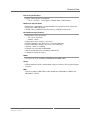
Switch Fabric Key Features
• Four 10/100/1000Base-T ports at front panel
- Electrical isolation: 1,500 Vrms
• Auto-negotiation
• High-speed non-blocking, store-and-forward switching
• 8K MAC address lookup table with automatic learning and aging
• QoS (Quality of Service) support with 4 traffic classes (IEEE 802.1p tagged
frames)
• Layer 2 switching
• Back pressure or IEEE802.3x flow control
• Automatic MDI/MDI-X crossover (all ports)
Security Features
• MAC based access list (ACL) for traffic filtering
• Rate-limiting and storm control to prevent packet flooding from malicious peers
Supported Ethernet Standards
•
•
•
•
•
•
Transparent bridging: IEEE 802.1d, 2004
VLAN: IEEE 802.1q Rev D5.0, 2005
Port based VLANs: IEEE 802.1q Rev D5.0, 2005
Link aggregation: IEEE 802.3ad, 2005
Power over Ethernet support: IEEE 802.1af
Priority based switching: IEEE 802.1p
Power Over Ethernet Features
• Power over Ethernet functions on all ports
- PSE (Power Sourcing Equipment) function
- Supports supply classes 0 to 3
- Supplies up to four PD devices (up to 28 W total)
Front I/O
• 4 Ethernet ports on RJ45 or M12 connectors
• 4 link and activity Ethernet status LEDs (2 per channel)
Rear I/O
• 1 Ethernet link via PCIe®
CompactPCI® Serial
• Compliance with CompactPCI® Serial PICMG CPCI-S.0 Specification
• Peripheral slot
• Host interface: one PCI Express® x1 link
- PCIe® 1.x support
- Data rate up to 250 MB/s in each direction (2.5 Gbit/s per lane)
MEN Mikro Elektronik GmbH
20G301-00 E4 – 2012-10-04
3
Technical Data
Electrical Specifications
• Supply voltage/power consumption
- +12 V (-3%/+5%), 2.4 W approx. (without PoE), 28 W PoE max.
Mechanical Specifications
• Dimensions: conforming to CompactPCI® Serial specification for 3U boards
• Front panel: 4HP with ejector
• Weight: 162 g (with RJ45 connectors)/188 g (with M12 connectors)
Environmental Specifications
• Temperature range (operation):
- -40..+85°C (screened)
- Airflow: 1.0 m/s
• Temperature range (storage): -40..+85°C
• Relative humidity (operation): max. 95% non-condensing
• Relative humidity (storage): max. 95% non-condensing
• Altitude: -300 m to +3,000 m
• Climatic tests according to EN 68068
• Shock and vibration tested according to EN 61373
• Conformal coating on request
MTBF
• 211,019 h @ 40°C according to IEC/TR 62380 (RDF 2000)
Safety
• PCB manufactured with a flammability rating of 94V-0 by UL recognized manufacturers
EMC
• Tested according to EN 55022 (radio disturbance), IEC1000-4-2 (ESD) and
IEC1000-4-4 (burst)
MEN Mikro Elektronik GmbH
20G301-00 E4 – 2012-10-04
4
Block Diagram
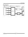
Block Diagram
F
R
Front connector
Options
Rear I/O connector
Port 1
F
Gb Eth
Digital interface
PHY
Port 2
F
Gb Eth
Gb Eth
CompactPCI®
Serial P6
RJ45 or M12 connectors
R
Switch Device
10/100/1000Base‐T
Gb Eth
F
Gb Eth
Port 4
F
Gb Eth
Ethernet Controller
PCIe x1
CompactPCI® Serial P1
Port 3
R
MEN Mikro Elektronik GmbH
20G301-00 E4 – 2012-10-04
5
Configuration Options
Configuration Options
Ethernet Switch
• Fixed managed version
- With fixed configuration according to customer requirements
Front Connectors
• RJ45 connectors or M12 connectors
Rear I/O
• CompactPCI® P6 connector
- For fifth Gigabit Ethernet 1000Base-T port (10/100 Mbit/s not supported)
Environmental specifications
• Conformal coating
Cooling Concept
• Also available with conduction cooling in MEN CCA frame
Please note that some of these options may only be available for large volumes.
Please ask our sales staff for more information.
For available standard configurations see online data sheet.
MEN Mikro Elektronik GmbH
20G301-00 E4 – 2012-10-04
6
Product Safety
Product Safety
!
Electrostatic Discharge (ESD)
Computer boards and components contain electrostatic sensitive devices.
Electrostatic discharge (ESD) can damage components. To protect the board and
other components against damage from static electricity, you should follow some
precautions whenever you work on your computer.
• Power down and unplug your computer system when working on the inside.
• Hold components by the edges and try not to touch the IC chips, leads, or circuitry.
• Use a grounded wrist strap before handling computer components.
• Place components on a grounded antistatic pad or on the bag that came with the
component whenever the components are separated from the system.
• Store the board only in its original ESD-protected packaging. Retain the original
packaging in case you need to return the board to MEN for repair.
MEN Mikro Elektronik GmbH
20G301-00 E4 – 2012-10-04
7
About this Document
About this Document
This user manual describes the hardware functions of the board, connection of
peripheral devices and integration into a system. It also provides additional
information for special applications and configurations of the board.
The manual does not include detailed information on individual components (data
sheets etc.). A list of literature is given in the appendix.
History
Issue
Comments
Date
E1
First issue
2011-04-26
E2
Minor change to "Ethernet switch" chapter (MII ->
GMII digital interface)
2011-05-05
E3
Rear port restricted to 1000Base-T,
power consumption value added
2012-02-03
E4
General update (PoE)
2012-10-04
Conventions
This sign marks important notes or warnings concerning the use of voltages which
can lead to serious damage to your health and also cause damage or destruction of
the component.
!
italics
bold
monospace
This sign marks important notes or warnings concerning proper functionality of the
product described in this document. You should read them in any case.
Folder, file and function names are printed in italics.
Bold type is used for emphasis.
A monospaced font type is used for hexadecimal numbers, listings, C function
descriptions or wherever appropriate. Hexadecimal numbers are preceded by "0x".
comment
Comments embedded into coding examples are shown in green color.
hyperlink
Hyperlinks are printed in blue color.
The globe will show you where hyperlinks lead directly to the Internet, so you can
look for the latest information online.
IRQ#
/IRQ
Signal names followed by "#" or preceded by a slash ("/") indicate that this signal is
either active low or that it becomes active at a falling edge.
in/out
Signal directions in signal mnemonics tables generally refer to the corresponding
board or component, "in" meaning "to the board or component", "out" meaning
"coming from it".
Vertical lines on the outer margin signal technical changes to the previous issue of
the document.
MEN Mikro Elektronik GmbH
20G301-00 E4 – 2012-10-04
8
About this Document
Legal Information
Changes
MEN Mikro Elektronik GmbH ("MEN") reserves the right to make changes without further notice to any products
herein.
Warranty, Guarantee, Liability
MEN makes no warranty, representation or guarantee of any kind regarding the suitability of its products for any
particular purpose, nor does MEN assume any liability arising out of the application or use of any product or
circuit, and specifically disclaims any and all liability, including, without limitation, consequential or incidental
damages. TO THE EXTENT APPLICABLE, SPECIFICALLY EXCLUDED ARE ANY IMPLIED
WARRANTIES ARISING BY OPERATION OF LAW, CUSTOM OR USAGE, INCLUDING WITHOUT
LIMITATION, THE IMPLIED WARRANTIES OF MERCHANTABILITY AND FITNESS FOR A
PARTICULAR PURPOSE OR USE. In no event shall MEN be liable for more than the contract price for the
products in question. If buyer does not notify MEN in writing within the foregoing warranty period, MEN shall
have no liability or obligation to buyer hereunder.
The publication is provided on the terms and understanding that:
1. MEN is not responsible for the results of any actions taken on the basis of information in the publication, nor
for any error in or omission from the publication; and
2. MEN is not engaged in rendering technical or other advice or services.
MEN expressly disclaims all and any liability and responsibility to any person, whether a reader of the publication
or not, in respect of anything, and of the consequences of anything, done or omitted to be done by any such person
in reliance, whether wholly or partially, on the whole or any part of the contents of the publication.
Conditions for Use, Field of Application
The correct function of MEN products in mission-critical and life-critical applications is limited to the
environmental specification given for each product in the technical user manual. The correct function of MEN
products under extended environmental conditions is limited to the individual requirement specification and
subsequent validation documents for each product for the applicable use case and has to be agreed upon in writing
by MEN and the customer. Should the customer purchase or use MEN products for any unintended or
unauthorized application, the customer shall indemnify and hold MEN and its officers, employees, subsidiaries,
affiliates, and distributors harmless against all claims, costs, damages, and expenses, and reasonable attorney fees
arising out of, directly or indirectly, any claim or personal injury or death associated with such unintended or
unauthorized use, even if such claim alleges that MEN was negligent regarding the design or manufacture of the
part. In no case is MEN liable for the correct function of the technical installation where MEN products are a part
of.
Trademarks
All products or services mentioned in this publication are identified by the trademarks, service marks, or product
names as designated by the companies which market those products. The trademarks and registered trademarks
are held by the companies producing them. Inquiries concerning such trademarks should be made directly to those
companies.
Conformity
MEN products are no ready-made products for end users. They are tested according to the standards given in the
Technical Data and thus enable you to achieve certification of the product according to the standards applicable in
your field of application.
MEN Mikro Elektronik GmbH
20G301-00 E4 – 2012-10-04
9
About this Document
RoHS
Since July 1, 2006 all MEN standard products comply with RoHS legislation.
Since January 2005 the SMD and manual soldering processes at MEN have already been completely lead-free.
Between June 2004 and June 30, 2006 MEN’s selected component suppliers have changed delivery to RoHScompliant parts. During this period any change and status was traceable through the MEN ERP system and the
boards gradually became RoHS-compliant.
WEEE Application
The WEEE directive does not apply to fixed industrial plants and tools. The compliance is the responsibility of the
company which puts the product on the market, as defined in the directive; components and sub-assemblies are
not subject to product compliance.
In other words: Since MEN does not deliver ready-made products to end users, the WEEE directive is not
applicable for MEN. Users are nevertheless recommended to properly recycle all electronic boards which have
passed their life cycle.
Nevertheless, MEN is registered as a manufacturer in Germany. The registration number can be provided on
request.
Copyright © 2012 MEN Mikro Elektronik GmbH. All rights reserved.
Germany
MEN Mikro Elektronik GmbH
Neuwieder Straße 3-7
90411 Nuremberg
Phone +49-911-99 33 5-0
Fax +49-911-99 33 5-901
E-mail [email protected]
www.men.de
MEN Mikro Elektronik GmbH
20G301-00 E4 – 2012-10-04
France
MEN Mikro Elektronik SA
18, rue René Cassin
ZA de la Châtelaine
74240 Gaillard
Phone +33 (0) 450-955-312
Fax +33 (0) 450-955-211
E-mail [email protected]
www.men-france.fr
USA
MEN Micro, Inc.
24 North Main Street
Ambler, PA 19002
Phone (215) 542-9575
Fax (215) 542-9577
E-mail [email protected]
www.menmicro.com
10
Contents
Contents
1 Getting Started . . . . . . . . . . . . . . . . . . . . . . . . . . . . . . . . . . . . . . . . . . . . . . . . 12
1.1 Front panels . . . . . . . . . . . . . . . . . . . . . . . . . . . . . . . . . . . . . . . . . . . . . 12
1.2 Integrating the Board into a System . . . . . . . . . . . . . . . . . . . . . . . . . . 12
2 Functional Description . . . . . . . . . . . . . . . . . . . . . . . . . . . . . . . . . . . . . . . . . .
2.1 Power Supply. . . . . . . . . . . . . . . . . . . . . . . . . . . . . . . . . . . . . . . . . . . .
2.2 Ethernet Ports . . . . . . . . . . . . . . . . . . . . . . . . . . . . . . . . . . . . . . . . . . .
2.3 Ethernet Switch . . . . . . . . . . . . . . . . . . . . . . . . . . . . . . . . . . . . . . . . . .
2.3.1
Configuration of the Switch . . . . . . . . . . . . . . . . . . . . . . . . .
2.4 Power over Ethernet . . . . . . . . . . . . . . . . . . . . . . . . . . . . . . . . . . . . . .
2.5 Front Panel Status LEDs . . . . . . . . . . . . . . . . . . . . . . . . . . . . . . . . . . .
13
13
13
15
15
16
16
3 Appendix . . . . . . . . . . . . . . . . . . . . . . . . . . . . . . . . . . . . . . . . . . . . . . . . . . . . . 17
3.1 Literature and Web Resources . . . . . . . . . . . . . . . . . . . . . . . . . . . . . . . 17
3.2 Finding out the Board’s Article Number, Revision and
Serial Number . . . . . . . . . . . . . . . . . . . . . . . . . . . . . . . . . . . . . . . . . . . 17
Figures
Figure 1. Front Panels: Standard RJ45 model (left) and optional
M12 model (right) . . . . . . . . . . . . . . . . . . . . . . . . . . . . . . . . . . . . . . . . 12
Figure 2. Labels giving the board’s article number, revision and
serial number . . . . . . . . . . . . . . . . . . . . . . . . . . . . . . . . . . . . . . . . . . . . 17
Tables
Table 1.
Table 2.
Table 3.
Table 4.
Table 5.
MEN Mikro Elektronik GmbH
20G301-00 E4 – 2012-10-04
Pin assignment of the Gigabit Ethernet RJ45 connectors. . . . . . . . . . .
Pin assignment of the Gigabit Ethernet M12 connectors . . . . . . . . . . .
Default switch configuration at startup . . . . . . . . . . . . . . . . . . . . . . . .
Power over Ethernet configuration. . . . . . . . . . . . . . . . . . . . . . . . . . . .
Ethernet port status LEDs. . . . . . . . . . . . . . . . . . . . . . . . . . . . . . . . . . .
13
14
15
16
16
11
Getting Started
1
Getting Started
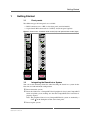
1.1
Front panels
Two different types of front panels are available:
• 4 RJ45 connectors on a 4-HP (1-slot) front panel (standard model)
• 4 8-pin female M12 connectors on a 4-HP (1-slot) front panel (option)
Figure 1. Front Panels: Standard RJ45 model (left) and optional M12 model (right)
CompactPCI ®
CompactPCI ®
L A
1
L A
1
Serial
L A
2
Serial
X1
X1
X2
X2
X3
X3
X4
X4
L A
4
L A
3
L A
4
G301
1.2
L A
2
L A
3
G301
Integrating the Board into a System
You can use the following check list when installing the board in a system for the
first time and with minimum configuration.
Power-down the system.
Insert the G301 into a CompactPCI Serial peripheral slot of your CompactPCI
Serial or hybrid system, making sure that the CompactPCI Serial connector is
properly aligned.
Note: The peripheral slots of every CompactPCI Serial system are marked by a
circle on the backplane and/or at the front panel.
Power-up the system.
MEN Mikro Elektronik GmbH
20G301-00 E4 – 2012-10-04
12
Functional Description
2
Functional Description
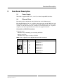
2.1
Power Supply
The G301 is supplied with +12V (-3%/+5%) via the CompactPCI Serial bus.
2.2
Ethernet Ports
Depending on the configuration, the G301 has four or five Ethernet ports.
Four Gigabit Ethernet ports are available at the front panel on either RJ45 or 8-pin
female M12 connectors. An optional fifth Gigabit Ethernet port can be made
available via the P6 connector (not assembled on standard models, pin assignment
compliant with the CompactPCI Serial standard for peripheral boards).
Connection via RJ45 Connectors
Connector types:
• Modular 8/8-pin mounting jack according to FCC68
• Mating connector:
Modular 8/8-pin plug according to FCC68
Table 1. Pin assignment of the Gigabit Ethernet RJ45 connectors
Pin
1
8
MEN Mikro Elektronik GmbH
20G301-00 E4 – 2012-10-04
Name
Description
1
D_1+
Gigabit pair 1 +
2
D_1-
Gigabit pair 1 -
3
D_2+
Gigabit pair 2 +
4
D_3+
Gigabit pair 3 +
5
D_3-
Gigabit pair 3 -
6
D_2-
Gigabit pair 2 -
7
D_4+
Gigabit pair 4 +
8
D_4-
Gigabit pair 4 -
13
Functional Description
Connection via M12 Connectors
Connector types:
• 8-pin M12 connector, female, A-coded
(Phoenix Contact 1436974 SACC-DSIV-FS-8CON-L90 SCO)
• Mating connector:
8-pin M12 connector, e.g., CONEC "SAL-12S-RS8-2/G3" 43-10980
Table 2. Pin assignment of the Gigabit Ethernet M12 connectors
Pin
7
8
1
2
6
5
3
4
MEN Mikro Elektronik GmbH
20G301-00 E4 – 2012-10-04
Name
Description
1
D_3-
Gigabit pair 3 -
2
D_4+
Gigabit pair 4 +
3
D_4-
Gigabit pair 4 -
4
D_1-
Gigabit pair 1 -
5
D_2+
Gigabit pair 2 +
6
D_1+
Gigabit pair 1 +
7
D_3+
Gigabit pair 3 +
8
D_2-
Gigabit pair 2 -
14
Functional Description
2.3
Ethernet Switch
The G301 uses a 5-port 10/100/1000Base-T switch component, the Marvell
88E6171. The switch provides 10/100/1000 Mbits/s configuration possibility on the
four front Ethernet ports and 1000 Mbits/s on the rear Ethernet port.
It is also possible to configure each port in half-duplex or full-duplex.
The switch characteristics are:
• Four external front ports configurable as 10/100/1000 Mbits/s and one rear port
fixed to 1000 Mbits/s
• GMII digital interface (not supported in standard G301 models)
• Each external port is configurable in half-duplex or full-duplex mode
• Non-blocking wire speed switching
• Store-and-forward mode
• Auto negotiation
• Port mirroring
• Port monitoring
• Flow control
• VLAN support
• Automatic MDI/MDI-X crossover (all ports)
• Port based frame priorization
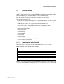
2.3.1
Configuration of the Switch
The G301 loads the following standard configuration for all ports at startup:
Table 3. Default switch configuration at startup
Setting
Default
Duplex mode
Full Duplex
Port speed
Auto-Negotiate
VLAN (port-based)
Off
QoS (Quality of Service)
Off
Port mirroring and port monitoring
Off
Port trunking
Off
Power over Ethernet functionality
PSE functionality enabled
By using a customer-specific configuration EEPROM, the G301 can act similarly to
a managed switch with fixed settings. Please contact MEN if you need a switch with
a non-standard configuration.
MEN Mikro Elektronik GmbH
20G301-00 E4 – 2012-10-04
15
Functional Description
2.4
Power over Ethernet
All front panel ports of the G301 support Power over Ethernet PSE ("power
sourcing equipment") functionality according to IEEE802.3af.
The G301 can deliver power to up to four PD ("powered device") devices.
Table 4. Power over Ethernet configuration
Class
!
Number of possible
devices
Power range
0
0.44..12.96 W
2
1
0.44..3.84 W
4
2
3.84..6.49 W
4
3
6.49..12.95 W
2
A combination of different classes is also possible. Please note, however, that the
combined power level drawn by connected PDs must not exceed 28 W!
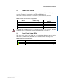
2.5
Front Panel Status LEDs
The front panel features two LEDs for each of the four Ethernet ports to display
their status (LNK and ACT). The LEDs act as described in the following table.
Table 5. Ethernet port status LEDs
LED
L
Ethernet link status (on = link established)
A
Ethernet traffic activity status (blink = Ethernet traffic running)
MEN Mikro Elektronik GmbH
20G301-00 E4 – 2012-10-04
Description
16
Appendix
3
Appendix
3.1
Literature and Web Resources
• G301 data sheet with up-to-date information and documentation:
www.men.de/products/02G301-.html
3.2
Finding out the Board’s Article Number, Revision and
Serial Number
MEN user documentation may describe several different models and/or hardware
revisions of the G301. You can find information on the article number, the board
revision and the serial number on two labels attached to the board.
• Article number: Gives the board’s family and model. This is also MEN’s ordering number. To be complete it must have 9 characters.
• Revision number: Gives the hardware revision of the board.
• Serial number: Unique identification assigned during production.
If you need support, you should communicate these numbers to MEN.
Figure 2. Labels giving the board’s article number, revision and serial number
Complete article number
0*1-00
00.00.00
Revision number
Serial number
MEN Mikro Elektronik GmbH
20G301-00 E4 – 2012-10-04
17