1
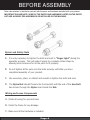
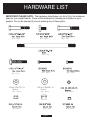
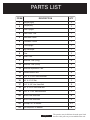
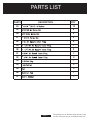
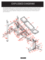
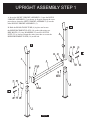
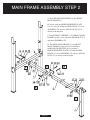
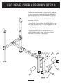
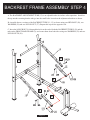
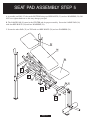
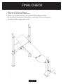
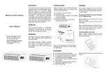
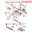
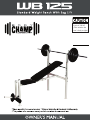
Maximum Weight
Limit is 250 lbs.
(This includes the
userʼs body weight)
SAFETY AND
AND CAUTION
SAFETY
CAUTION
W AR N IN G
Before Using Read All The Warnings And Obtain Instruction On The Use Of This Machine! Use
Only For Intended Exercise! DO NOT Modify The Machine!
Before Beginning Any Exercise Program, Consult With Your Doctor Or Health Physician.
Refer To The Manual Whenever You Have A Question.
Keep All Body Parts And Clothing Free From All Moving Objects And Parts Of This Machine!
Always Use A Spotter When Attempting To Workout.
If The User Needs More Assistance, Please Contact A Technical Consultant Before Attempting To
Use The Machine.
Keep Your Fingers, Body Parts, Children And Pets Away From Moving Parts.
Warm Up Before Each Workout And Cool Down After Each Workout.
Do Not Allow Children Near This Equipment! Teenagers Must Be Supervised!
Inspect The Machine Before Each Use, Make Sure All Of The Connections Are Tightly Secured.
Do Not Over Tighten The Bolts Or Screws As It Could Result In Bending The Steel Or Plastic.
Inspect The Machine For Tears And Broken Welds And Make Sure To Do Routine Maintenance On
The Unit Before Use.
If The Parts In The Box Does Not Match The Owner’s Manual, Please Do Not Assemble And Contact
The Customer Service Department Immediately For Assistance.
If The Machine Is Not In Proper Working Condition As The Above Points, Please Do Not Use The
Machine.
This Product Is For Consumer User Only And It Is Not Meant For Commercial Use.
If The User Does Not Follow These Warnings, It Could Result In Serious Injury Or Even Death.
The Minimum Suggested Clearance For Safe Exercise 7’ Long 7’ Wide.
������
WARRANTY INFORMATION
CA 91789
BEFORE ASSEMBLY
BEFORE
ASSEMBLY
Take a
a few
to familiarize
yourself withyourself
the parts and
hardware
included parts
with your
product.
Take
fewminutes
moments
to familiarize
with
the specific
hardware
IMPORTANT PLEASE NOTE: SOME OF THE PARTS AND HARDWARE LISTED ON THE PARTS
included with your product. Make sure all the parts and hardware are included in
LIST ARE ALREADY PRE-ASSEMBLED OR INSTALLED ON THE MACHINE.
the cartons and examine them for any damage that may have occurred in
transport. Some parts may be pre-assembled and pre-installed
Nylon Lock Safety Nuts
A. It is only necessary to tighten the bolts and nuts to “finger tight” during the
assembly process. This will make it easier to complete certain steps by
allowing more tolerance for all the parts to fit properly.
B. Do not tighten all the nuts onto the bolts securely until after you have
completed assembly of your product.
C. Use wrenches, pliers, or ratchet and sockets to tighten the bolts and nuts.
D. The Nylon Nut should thread onto the Hex Bolt until the end of the Hex Bolt
has broken through the Nylon insert inside the Nut.
Wiring and Loose Components
A. Check all wiring for rips and tears
B. Check the frame for any damage
C. Make sure all the hardware is included
Page 4
HARDWARE LIST
IMPORTANT PLEASE NOTE: The hardware listed below is a list of ALL the hardware
used on your weight bench. Some of this hardware is already pre installed on your
product. Do not be alarmed if you are missing any of these parts.
Qty: 8pcs
Qty: 3pcs
Qty: 1pc
Qty: 1pc
Qty: 1pc
(22)ø8.5Xø17X1.5t
Washer
Qty: 21pcs
Qty: 9pcs
Qty: 8pcs
(23)ø10.5Xø20X1.5t
Washer
Qty: 4pcs
Qty: 3pcs
Page 5
Qty: 2pcs
Qty: 12pcs
Qty: 2pcs
PARTS LIST
ITEM#
DESCRIPTION
QTY
1
Upright(Right)
1
2
Upright(Left)
1
3
Down Upright
2
4
Rear Cross Tube
1
5
Rear Main Frame
1
6
Front Main Frame
1
7
Front Upright
1
8
Leg Developer
1
9
Tube
1
10
Roller Tube
1
11
Backrest Tube (Long)
2
12
Backrest Tube (Short)
2
13
Backrest Adjustment Tube
1
14
Reinforcement Plate
5
15
5/16" X 2 -3/16" Hex Head Bolt
8
16
3/8" X 6 -7/8" Bolt
1
17
5/16" X 5/8" Hex Head Bolt
3
18
3/8" X 2 -3/8" Hex Head Bolt
1
19
5/16" X 1 -3/4" Hex Head Bolt
1
20
M6X35 Hex Head Bolt
8
21
M6X15 Hex Head Bolt
2
22
φ8.5Xφ17X1.5t Washer
23
φ10.5X φ 20X1.5t Washer
21
4
Page 6
The quantity may be different from the parts listed
because some parts are pre-assembled on the unit.
PARTS LIST
�����
�����������
���
��
��
� 6.5× � 13×1.0t Washer
��
5/16"× 8 . 0 t Ny l o n N u t
�
��
3/8"×1 0 t N y lo n N u t
�
��
M6×6.0t Nylon Nut
�
��
1"×1.5t S q u ar e I n n e r P l u g
�
��
1 - 1/2"×1.5t Square Inner Plug
�
��
1 - 1/4"×1.5t Square Inner Plug
�
��
� 25×1.5t Round Inner Plug
�
��
� 19×1.5t Round Inner Plug
�
��
� 25 End Cap
�
��
Foam Roller
�
��
Pad
�
��
Backres t P a d
�
��
User's M a n u a l
�
Page 7
The quantity may be different from the parts listed
because some parts are pre-assembled on the unit.
EXPLODED DIAGRAM
The following diagram is provided to help you familiarize yourself with the parts and hardware that will be
used during the assembly process. Please note that not all of the parts and hardware you see here will be
used while you are assembling the machine because some of these items are already pre-installed. Please
continue to the next page to begin the assembly process and use this page only as a reference guide for
parts and hardware.
Page 8
UPRIGHT ASSEMBLY STEP 1
A. Insert the RIGHT UPRIGHT ASSEMBLY (1) into the DOWN
UPRIGHT ASSEMBLY (3) as shown in diagram. Repeat the same
procedure to insert the LEFT UPRIGHT ASSEMBLY (2) into the
other DOWN UPRIGHT ASSEMBLY (3).
B. Hold the REAR CROSS TUBE (4) in place and secure
the REINFORCEMENT PLATE (14) on the right using two
HEX BOLTS (15), four WASHERS (22) and two NYLON
NUTS (25) as shown. Repeat the same procedure to secure the
REINFORCEMENT PLATE (14) on the left.
Page 9
MAIN FRAME ASSEMBLY STEP 2
A. Insert REAR MAIN FRAME (5) into FRONT
MAIN FRAME (6).
B. Secure with one REINFORCEMENT PLATE
(14) on each side using two HEX BOLTS (15), four
WASHERS (22) and two NYLON NUTS (25) as
shown in the diagram.
C. Install FRONT UPRIGHT (7) TO FRONT MAIN
FRAME (6) and secure with three HEX BOLTS (17)
and three WASHERS (22).
D. The REAR MAIN FRAME (5) and FRONT
MAIN FRAME (6) may now be assembled to
the REAR CROSS TUBE (4) by securing a
REINFORCEMENT PLATE (14) with two HEX
BOLTS (15), four WASHERS (22) and two NYLON
NUTS (25) as shown in the diagram.
Page 10
LEG DEVELOPER ASSEMBLY STEP 3
A. Install LEG DEVELOPER (8) to the FRONT UPRIGHT
(7), which is attached to the MAIN FRAME ASSEMBLY
using one HEX BOLT (18), two WASHERS (23) and one
NYLON NUT (26). Do not over-tighten the HEX BOLT
(18) as this will prevent the LEG DEVELOPER from
functioning smoothly.
B. Insert TUBE (9) through the LEG DEVELOPER (8) and
secure with one HEX BOLT (19), two WASHERS (22) and
one NYLON NUT (25). Then, apply the END CAP (33) to
the end of TUBE (9) as shown in the diagram.
C. Insert ROLLER TUBE (10) through the holes on
the LEG DEVELOPER (8), then, slide in two FOAM
ROLLERS (34) as shown in the diagram.
Page 11
BACKREST FRAME ASSEMBLY STEP 4
A. The BACKREST ADJUSTMENT TUBE (13) is an adjustable tube for incline or flat operation. Install on
the top notches ensuring that the tabs go into the small holes located on the adjustment brackets as shown.
B. Assemble the two sections of the BACKREST TUBE (11, 12) as shown using one HEX BOLT (20), two
WASHERS (24) and one NYLON NUT (27). Repeat this step for the opposite side.
C. Insert the LONG BOLT (16) through the holes at the end of both the BACKREST TUBES (12) and the
tube on the FRONT MAIN FRAME (6), and secure them from both sides using two WASHERS (23) and two
NYLON NUTS (26).
Page 12
SEAT PAD ASSEMBLY STEP 5
A. Assemble one PAD (35) first at the BOTTOM using two HEX BOLTS (21) and two WASHERS (24). DO
NOT over tighten hardware as this may damage your pad.
B. The LARGE PAD (36) must be the CENTER pad for proper assembly. Secure the LARGE PAD (36)
with four HEX BOLTS (20) and four WASHERS (24).
C. Secure the other PAD (35) on TOP with two HEX BOLTS (20) and two WASHERS (24).
Page 13
FINAL CHECK
•
•
•
•
Make sure all bolts are tightened.
Check for loose parts and components
Check to see if there are any tears or bends in the welding or metal.
Be sure that all adjustment locking devices and safety devices are properly
located and fully engaged prior to use!
Page 14
Thanks for choosing
WB 125
Retailer:
���������������������
���������������������
����������������
���������������������
�������������������
�������������������������������
Page 15
version: 6-16-2009