1
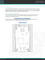
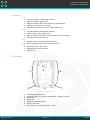
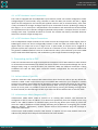
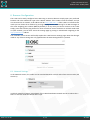
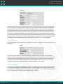
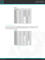
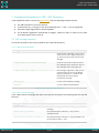
User Manual Version 0.0 Preliminary Release Copyright © 2013 x-io Technologies Ltd. www.x-io.co.uk x-OSC User Manual v0.0 Release date: 23 May 2013 Contents 1. Overview...............................................................................................................................................3 2. Open Sound Control (OSC) ...................................................................................................................3 3. Features ................................................................................................................................................4 4. Hardware ..............................................................................................................................................4 4.1. x-OSC Hardware Input Connections..............................................................................................5 4.2. x-OSC Hardware Output Connections...........................................................................................5 5. Connecting to the x-OSC ......................................................................................................................5 5.1. Ad hock Mode (Cyan LED) .............................................................................................................5 5.2. Infrastructure Mode (Magenta LED) .............................................................................................5 6. Browser Configuration .........................................................................................................................6 6.1. Network Settings...........................................................................................................................6 6.2. OSC Settings ..................................................................................................................................7 6.3. Input Settings ................................................................................................................................7 6.4. Output Settings .............................................................................................................................8 7. Communicating with the x-OSC – OSC Dictionary................................................................................9 7.1. OSC message summery .................................................................................................................9 7.1.1. x-OSC to host messages .........................................................................................................9 7.1.2. Host to x-OSC messages ........................................................................................................9 7.2. Full OSC Message Documentation ..............................................................................................10 7.2.1. x-OSC to host messages .......................................................................................................10 7.2.2. Host to x-OSC messages ......................................................................................................11 www.x-io.co.uk 2 / 13 © 2013 x-OSC User Manual v0.0 Release date: 23 May 2013 1. Overview x-OSC is a robust high-performance 32 channel wireless interface device that makes it simple to control and respond to a limitless range of electronics without having to learn a new programming language or install device drivers. All you need is a WiFi enabled computer, some basic programming skills and you are ready to make sophisticated interactive systems. 2. Open Sound Control (OSC) x-OSC communications take place over WiFi using the ubiquitous OSC protocol, which is a versatile network protocol, supported in more than 80 different programming languages and software environments. For an extensive list see: http://opensoundcontrol.org/implementations A fuller description of OSC is provided in section7. We are maintaining a growing range of x-OSC example projects for the most popular platforms/environments here: http://x-io.co.uk/x-osc www.x-io.co.uk 3 / 13 © 2013 x-OSC User Manual v0.0 Release date: 23 May 2013 3. Features Inputs 16x independently configurable channels Modes: analogue, digital, serial High performance ADC: 14-bit resolution, 350 Hz update Analogue comparator functionality Selectable pull-up/down resistors (digital mode only) Outputs 16x independently configurable channels Modes: digital, pulse, PWM, serial High performance PWM: 5 Hz to 250 kHz up to 16-bit resolution Source/sink 50 mA per channel WiFi Supports ad hoc and infrastructure networks Fully configurable via standard internet browser. Other Small form factor: 45 x 32 mm Regulated 3.3V, 700 mA output Battery level 4. Hardware 3 1 5 4 2 6 7 Figure 1: x-OSC top view 1. 2. 3. 4. 5. 6. 7. www.x-io.co.uk 16 analogue/digital inputs 16 digital outputs (inc. high-speed PWM for ‘analogue’ output) Ping button Status LED Regulated power out (3.3 V) Battery connector Battery output or power input (3.5 – 5.5 V) 4 / 13 © 2013 x-OSC User Manual v0.0 Release date: 23 May 2013 4.1. x-OSC Hardware Input Connections The x-OSC is equipped with 16 independent input channels, which can each be configured to either analogue digital or serial modes, using a browser or OSC over WiFi (see sections 6.3 and 7). Digital inputs can be configured to use internal pull-up/down resistors and, to minimise latency, their state is only transmitted on change. Analogue inputs may be connected to sensors producing a voltage in the range 0 – 3.3 V. Each input is sampled with 13-bit resolution and measurements aretransmitted at a specified rate of up to 350 Hz. Analogue inputmode also provides a ‘compare’ function to send a message each time a specified threshold is crossed. This enables low-latency threshold detection without the need for a high message rate. 4.2. x-OSC Hardware Output Connections The 16 independent output channels on the x-OSC can each be configured to output digital, pulse or PWM signals, which can also be configuredby browser or OSC over WiFi (see sections 6.3 and 7). In digital mode, an output can be set to high or low. In pulse mode, an output can be triggered to generate a pulse with a period of 1 ms to 1 minute at a resolution of 1 ms. An output in PWM mode can generate a PWM waveform from 5 Hz to 250 kHz with a duty cycle resolution up to 16-bit. PWM may be used witha fixed frequency and variable duty cycle to approximate an analogue signal. 5. Connecting to the x-OSC x-OSC can communicate with single or multiple host computers over a WiFi network in either ad hock or infrastructure networkmodes. By default the device will be in ad hock mode although this can be changed easily using an internet browser (see section6). While the network connection is being established the LED will flash; upon successful network configuration the LED will remain on constantly. 5.1. Ad hock Mode (Cyan LED) In ad hoc mode the x-OSC creates a WiFi network that other devices are able to join. By default this network is called “x-OSC” and will show up as an available WiFi network in your computer’s network settings (this network name (SSID) can be changed in the device settings see section 6). The x-OSC’s wireless ad hock network is open by default although WEP security can be enabled (again, see section 6). At any time it is possible to enter ad hock mode by pressing and holding the ping button for three seconds, the LED will begin to flash Cyan when the device switches back to ad hock mode. 5.2. Infrastructure Mode (Magenta LED) Infrastructure mode allows x-OSC to connect to an existing WiFi network. The devicecan be configured to have a static IP address or to obtain one dynamically from the network server using DHCP. If the x-OSC IP address is unknown simply press the ping button (see section 4), which will cause the x-OSC to broadcast an OSC message indicating the IP addresson its outgoing port number (8000 by default). Alternatively, another network device can broadcasta ping OSC message to achieve the same result. Infrastructure mode enables multiple x-OSC devices to operate on the same network and to be addressed by multiple host computersconnected to the same network. www.x-io.co.uk 5 / 13 © 2013 x-OSC User Manual v0.0 Release date: 23 May 2013 6. Browser Configuration The x-OSC can be easily configured over WiFi using an internet browser. Simply open your preferred browser and in the address bar type in the x-OSC IP address. If the x-OSC is in ad hock mode, and you are connected to its network, its IP address will be http://169.254.1.1. If the x-OSC is in infrastructure mode you can obtain the IP address by pressing the ping button and listening for an OSC message on the x-OSC outgoing port number (8000 by default). If at any time you cannot connect to the x-OSC simply press and hold the ping button for three seconds to return the device to ad hock mode with an open network; you can then access the settings page by joining its networkand navigating to the http://169.254.1.1 address. The remainder of this section will briefly explain the x-OSC browser settings page. Note that changes made to any of these settings are only applied when the Save Settings button is pressed. 6.1. Network Settings In the Network section, the x-OSC can be switched between ad hock and infrastructure modes (see section 5). In ad hock mode the network name (SSID) of the x-OSC hosted WiFi network can be set. When the xOSC is in ad hock mode the LED will shine cyan. www.x-io.co.uk 6 / 13 © 2013 x-OSC User Manual v0.0 Release date: 23 May 2013 In infrastructure mode you can enter the name of the network (SSID) that you would like the x-OSC to join, setting the security mode accordingly. Security types Open, WPA and WPA2 are supported where the latter two require entry of a security passphrase. Inthis section you can disable DHCP if you would like to specify a static IP address for x-OSC. When you are happy that you have entered the correct infrastructure settings click the Save Settings button to reboot the x-OSC with the new infrastructure settings. The LED will then flash magenta until it has successfully joined the network when it will shine constantly. Connection should take approximately 30 seconds, if flashing continues for more than one minute then review the infrastructure settings for errors by pressing and holding the ping button for three seconds to revert the x-OSC to ad hock mode, see section 6 above. 6.2. OSC Settings In the OSC section, the IP and port settings for the receipt and delivery of OSC messages can be configured. The host IP is the IP address of the devicethat the x-OSC will deliver messages to. The default IP address is 255.255.255.255 which is a special broadcast address which means that all devices on the network will receive messages from the x-OSC. The outgoing port specifies the port on which your computer should listen for OSC messages and the incoming port specifies the port to which your computer should send. The local IP shows the current IP address of the x-OSC. 6.3. Input Settings The input section is whereindividual input channels can be configured. Each input channel can be set to be digital or analogue as described in section 4.1. In digital mode the pull up/down state can be set, in analogue mode the compare threshold can be set (range 0.0 – 1.0). At the top of this section is the message rate for the analogue input readings (0.0 – 350.0Hz). www.x-io.co.uk 7 / 13 © 2013 x-OSC User Manual v0.0 Release date: 23 May 2013 6.4. Output Settings The output section is where the individual output channel modes can be configured. Each channel can be set to digital, pulse or PWM modes with relevant parameters for each mode as shown in Figure 2as described in section 4.2. Figure 2 Output browser settings www.x-io.co.uk 8 / 13 © 2013 x-OSC User Manual v0.0 Release date: 23 May 2013 7. Communicating with the x-OSC – OSC Dictionary x-OSC Implements OSC 1.0 as per the specification with the following exceptions/notes: the address pattern is not case sensitive. character lists (e.g. *“string+”) or the associated operators “-” and “!” are not supported. float and integer arguments are interchangeable for all Boolean arguments represented as integers, values less than or equal to 0 are false and values greater than 0 are true. 7.1. OSC message summery This section provides a short look up table for the x-OSC OSC dictionary. 7.1.1. x-OSC to host messages Message Description /input/digital,iiiiiiiiiiiiiiii each integer argument is the current state of one of the digital inputs (0 or 1). Sent only when the state of a pin changes. /input/analog,ffffffffffffffff each f is the current value of one of the analogue input channels. Sent at the analogue input message rate. /input/analog/compare,iiiiiiiiiiiiiiii Each integer argument is the current compare state of one of the digital inputs (0 if below or 1 if above the threshold). Sent only when a threshold is crossed. /battery,f f is the current battery voltage. /ping,s s is the x-OSC local IP address. Table 1: x-OSC to host message summery 7.1.2. Host to x-OSC messages If the x-OSC receives a message that does not match any message in the following table the LED will flash red. www.x-io.co.uk Message Description /input/rate,f f sets the message rate for the analogue input readings /input/analog/channel the specified input channel (1 - 16) is set to analogue mode. /input/analog/compare/channel,f the specified input channel (1 - 16) threshold is set to the value of f (0.0 – 1.0). 9 / 13 © 2013 x-OSC User Manual v0.0 Release date: 23 May 2013 /input/digital/channel the specified input channel (1 - 16) is set to digital mode. /input/digital/up/channel enables the pull up for specified digital input channel (1 - 16). /input/digital/down/channel enables the pull down for specified digital input channel (1 - 16). /output/digital/channel the specified output channel (1 - 16) is set to digital mode. /output/digital/state/channel,i where i (0 or 1) sets the state of the specified output channel. /output/pulse/channel triggers a pulse on the specified output channel (1 16) is set to pulse mode. Uses the last width and invert values. /output/pulse/width/channel,i triggers a pulse for i milliseconds on the specified channel. /output/pulse/invert/channel,i triggers a pulse on the specified channel (0 - 16), if i is 1 the pulse is inverted, else the pulse is normal. /output/pwm/channel the specified output channel (1 - 16) is set to PWM mode. /output/pwm/frequency/channel,f the specified output channel (1 - 16) is set to PWM mode with the frequency f (5.0 – 250000.0). /output/pwm/duty/channel,f the specified output channel (1 - 16) is set to PWM mode with the duty f (0.0 – 100.0). /led/set,iii the LED colour is set where iii are three rgb integers (0 - 255). /led/clear resets the LED to the network mode colour. /ping causes the x-OSC to broadcast its local IP address. Table 2: host to x-OSC message summery 7.2. Full OSC Message Documentation 7.2.1. x-OSC to host messages Digital input states /input/digital,iiiiiiiiiiiiiiii 16 integers describing the state of the digital input channels, 1 = high, 0 = low. Input channels not in digital mode will have a value of 0. This message is sent each time a digital input changes values. www.x-io.co.uk 10 / 13 © 2013 x-OSC User Manual v0.0 Release date: 23 May 2013 Analogue input values /input/analog,ffffffffffffffff 16 floats describing the value of the analogue input channels, 0.0 to 1.0 corresponding to 0 to 3.3V (13-bit resolution). Input channels not in analogue mode will have a value of 0. This message is sent at the analogue message rate. Analogue compare values /input/analog/compare,iiiiiiiiiiiiiiii 16 integers the state of the analogue compare channels, 1 = input is equal or greater than compare value, 0 = value is less than compare value. Input channels not in analogue mode will have a value of 0. This message is sent each time an analogue compare state changes values. Battery voltage /battery,f A single float describing the battery voltage in volts This message is sent every 5 seconds. Ping /ping,s A string representation of x-OSC’s local IP address. This message is sent each time the button is pressed or after a /ping message is received. Always a broadcast (i.e. destination IP = 255.255.255.255 7.2.2. Host to x-OSC messages Set analogue sample rate /input/rate,f The analogue sample rate in Hz. The value will be limited between 0 and 350 Hz. Set analogue channel /input/channel/analog Sets input to analogue mode for specified channel/s. Set analogue compare /input/channel/analog/compare,f Sets analogue compare value for specified channel/s. Value limited between 0 and 1. Also puts input/s into analogue mode. Set digital input /input/channel/digital Sets input to digital mode for specified channel/s. Set digital pull-up /input/channel/digital/up Sets pull-up resistor for digital mode for specified channel/s. Also puts input/s into digital mode. www.x-io.co.uk 11 / 13 © 2013 x-OSC User Manual v0.0 Release date: 23 May 2013 Set digital pull-down /input/channel/digital/down Sets pull-down resistor for digital mode for specified channel/s. Also puts input/s into digital mode. Set digital channel /output/channel/digital Sets output to digital mode for specified channel/s. Set digital channel /output/channel/digital/state,i Sets state of digital output for specified channel/s. Values less than 0 = low, values greater than 0 = high. Set pulse channel /output/channel/pulse Sets output to pulse mode for specified channel/s and start pulse. Set pulse width /output/channel/pulse/width,i Sets pulse width (in ms) of pulse output for specified channel/s and starts pulse. Values limited to integers between 1 ms and 60,000 (1 minute). Set pulse invert /output/channel/pulse/invert,i Sets pulse invert of pulse output for specified channel/s and starts pulse. Values < 0 = false, values > 0 = true. Set PWM channel /output/channel/pwm Sets output to PWM mode for specified channel/s. Set PWM frequency /output/channel/pwm/freq,f Sets frequency (in Hz) of PWM output for specified channel/s. Values limited to integers between 5 Hz and 250,000 Hz ms. Set PWM duty cycle /output/channel/pwm/duty,f Sets duty cycle (in %) of PWM output for specified channel/s (up to 16-bit resolution). Values limited to integers between 0 and 100 %. Set LED colour /led/set,iii Three integers corresponding to the RGB values of the LED. Each value is limited to between 0 and 255. Clear LED colour /led/clear Reverts LED to status colour www.x-io.co.uk 12 / 13 © 2013 x-OSC User Manual v0.0 Release date: 23 May 2013 Ping www.x-io.co.uk /ping Causes the x-OSC to respond with a ping message indicating its IP address. 13 / 13 © 2013