1
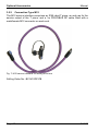
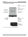
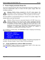
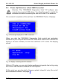
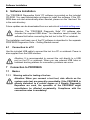
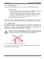
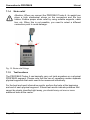
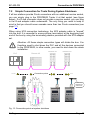
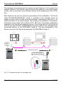
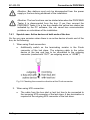
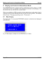
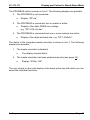
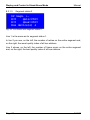
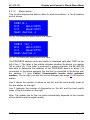
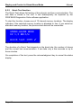
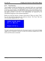
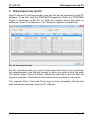
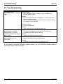
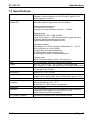
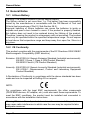
Manual
PROFIBUS Tester 4
BC-600-PB
FW version 1.13 (rev. 17)
Revision 2013-05-31
© Copyright 2013 Softing Industrial Automation GmbH
No part of this manual may be reproduced, photocopied, stored on a retrieval
system, transmitted, processed or translated without the express prior written
consent.
Contents
Introduction
1
1.1 General
1.2 Test Functions
1.2.1 Stand-alone mode of operation
1.2.2 PC mode of operation
2
Delivery Scope
3
Optional Accessories
3.1 D-sub adapter cable for testing live systems
3.2 Adapter Set for M12 Connection Technology
3.3 Fieldbus Shield Digital Leakage Current Clamp
3.4 Portable Power Supply
3.5 Service Interface for PROFIBUS DP
3.5.1 Connection Type D-sub
3.5.2 Connection Type M12
4
Connectors and Controls
5
Power Supply and Auto Power On
5.1 Power-Up Behaviour without USB Connection
5.2 Power-Up Behaviour when USB Connected
6
Software Installation
6.1 Connection to a PC
7
Connection to PROFIBUS
7.1 Basics
7.1.1 Warning notice for testing a live bus
7.1.2 Connection types
7.1.3 Adapter cable
7.1.4 Strain relief
7.1.5 Test locations
7.2 Simple Connection for Tests During System Shutdown
7.3 Connection for Testing a Live Bus
7.3.1 Connection via D-sub connector with service socket
7.3.2 Direct cable connection
7.3.3 Connection via M12 connector
6
6
6
6
7
8
9
9
9
10
10
11
11
12
13
14
14
15
16
16
16
16
16
17
17
18
18
19
20
21
22
23
7.4 Master Simulator and Topology Scan
7.4.1 Special case: Active devices at both ends of the bus
8
Display and Control in Stand-Alone Mode
8.1 Main Display
8.2 Operating Concept
8.3 Functions
8.3.1 Live Status function
8.3.1.1 Bus status summary
8.3.1.2 Segment status 1
8.3.1.3 Segment status 2
8.3.1.4 Station status
8.3.2 Quick Test function
8.3.3 Trend function
8.3.4 Master Simulator function
8.3.5 Settings and help functions
9
Data Import into the PC
10 Firmware Update
11 Maintenance and Servicing
12 Troubleshooting
13 Specifications
14 General Notes
14.1 Lithium Battery
14.2 CE Conformity
23
25
26
26
28
29
29
29
31
32
33
34
35
36
36
37
38
39
40
41
42
42
42
Introduction
1
Manual
Introduction
1.1
General
The PROFIBUS Tester 4 is a powerful tool that allows full testing of the bus
physics and bus communication on PROFIBUS DP segments.
Using the integrated master simulator, you can also test the bus physics if the
PLC is currently not in operation, or individually check “suspicious” bus
stations.
The tool is powered either through an external AC adapter, by direct
connection to 24 VDC or through an optional portable power supply unit.
1.2
Test Functions
The PROFIBUS Tester 4 automatically detects the baud rate or open circuit
voltage as soon as you connect it to a PROFIBUS DP segment.
You can then choose between two modes of operation for bus testing
depending on if you run it in stand-alone mode, or connect the PROFIBUS
Tester 4 to a PC or notebook. If required the master simulator can be enabled
in both modes if no other master is active.
1.2.1
Stand-alone mode of operation
In the stand-alone mode three test functions with simultaneous analysis of bus
physics and bus communication are available:
1. The Live Status shows the bus status and the details of the analysis
in real-time on the display.
2. To evaluate the bus health up to ten Quick Tests can be executed,
stored internally and imported by the PC software then.
3. To locate the causes of sporadic bus faults the long-term Trend logs
data for up to 41 days and stores them internally for later import by the
PC software.
Page 6
© 2013
BC-600-PB
1.2.2
Introduction
PC mode of operation
The PC software provides many additional features for performing, analyzing
and managing bus tests. Quick Tests and Trends stored in the tool can be
imported.
In the PC mode four main functions are available. Two of them provide
complex functionality that only experts need and that are accessed separately
from the standard functionality.
Standard functions:
1. The Network Status is a collection of information and test data
relating to a PROFIBUS network. It provides the basis for a
comprehensive evaluation of the bus health.
o
o
o
o
Quick test and user-controlled test with simultaneous analysis
of bus physics and bus communication
Topology scan
Test report
Master simulator
2. If sporadic faults occur in a PROFIBUS installation, the quality indexes
and critical protocol events should be monitored with the long-term
Trend over a prolonged period to locate the causes of bus problems.
Expert functions:
3. The function Frames enables the classic frame analysis.
4. The Oscilloscope permits the detail analysis of signal waveforms.
Softing
Page 7
Delivery Scope
2
Manual
Delivery Scope
The PROFIBUS Tester 4 comes in a carrying case comprising:
•
•
•
•
•
•
•
•
Test tool with RS485 interface
Wide-range power supply with European and US mains power cables
Connecting cable for direct power supply with 24 VDC
RS485 D-sub adapter cable BC-600-PB-CB-DSUB-2 “Standard”
(cable petrol blue, light connector) for PROFIBUS DP
USB cable, 3 m
Terminal block for trigger input/output
CD-ROM with driver software, PC software and detailed integrated
help system in English and German
PROFIBUS Tester 4 user manual and Getting Started manual for the
PROFIBUS Diagnostics Suite PC software
Fig. 1: BC-600-PB with carrying case
Page 8
© 2013
BC-600-PB
3
3.1
Optional Accessories
Optional Accessories
D-sub adapter cable for testing live systems
This D-sub adapter cable is optimized for reduced influence on live
PROFIBUS DP segment operation. Thereby it is most suitable for testing of
running plants. The risk of critical influences on bus operation which can cause
a plant standstill is significantly reduced. Attention: Using this cable it is not
possible to use the both active functions master simulator and topology
detection (see page 23).
Fig. 2: D-sub adapter cable with reduced influence on bus operation
Softing Order No.: BC-600-PB-CB-DSUB-1
3.2
Adapter Set for M12 Connection Technology
Using the M12 adapter set, you can connect the PROFIBUS Tester 4 to field
devices with M12 connectors. The set comprises an M12 adapter cable with
special pin layout and an M12 terminating resistor that you can screw on, if
required.
Fig. 3: Special adapter set for M12
Softing Order No.: BC-600-PB-CB-M12
Softing
Page 9
Optional Accessories
3.3
Manual
Fieldbus Shield Digital Leakage Current Clamp
When routing PROFIBUS cables in high-interference environments,
electromagnetic interference can affect the signal quality. By measuring the
shield currents with the digital leakage current clamp, you can locate EMC
problem areas and take appropriate countermeasures. The digital leakage
current clamp is supplied in a handy case, including measuring cables. There
is also an empty compartment for the fieldbus shield digital leakage current
clamp in the carrying case of the BC-600-PB.
Fig. 4: Fieldbus shield digital leakage current clamp
Softing Order No.: PB-LSZ-CHB3
3.4
Portable Power Supply
The portable power supply unit allows up to 4 hours of portable operation. The
power supply kit also includes a charger and a carrying case. Attention: Mains
connector type of charger station available for Europe only.
Fig. 5: Portable power supply
Softing Order No.: BC-MOST-PB
Page 10
© 2013
BC-600-PB
3.5
Optional Accessories
Service Interface for PROFIBUS DP
3.5.1
Connection Type D-sub
The D-sub service interface provides a PROFIBUS access point for testing if
the existing D-sub connectors have no service socket or if the bus stations are
connected via a terminal block. The service interface can power the
terminating resistor of the D-sub connector. You can thus use it as an active
bus termination at the beginning or end of the bus.
If the PLC allows dropping and adding bus stations on the live bus, you will
need this external bus termination to be able to exchange the first and last bus
stations without causing problems on the bus.
The compact unit is rail mounted like a terminal block and powered by an
external 24 VDC power supply. The package includes an 90° angled
PROFIBUS connector with a switchable terminating resistor.
Fig. 6: D-sub service interface for testing a live bus
Softing Order No.: BC-PBMB-PB-S
Softing
Page 11
Optional Accessories
3.5.2
Manual
Connection Type M12
The M12 service interface comprises an IP68 rated T piece, an end cap for the
service output of the T piece, and a 1m PROFIBUS DP cable fitted with a
male/female M12 connector on each end.
Fig. 7: M12 service interface for testing a live bus
Softing Order No.: BC-M12DP-PB
Page 12
© 2013
BC-600-PB
4
Connectors and Controls
Connectors and Controls
RS485
Connection to PROFIBUS DP
Display
Status display & operation
Function key 2
Detail selection
Funktionstaste 3
Start
Function key 1
Function selection
Funktionstaste 4
Back/Cancel
Power
Connection to
power supply
24 VDC
USB
Connection to notebook/PC
Status LED
Trigger input
Status LED
Trigger Output
Detail view:
Terminal block for
trigger input/output
Fig. 8: Connectors and status displays on the BC-600-PB
Softing
Page 13
Power Supply and Auto Power On
5
Manual
Power Supply and Auto Power On
The tool is powered with 24 VDC either through the external AC adapter or by
using the single-ended cable for direct 24 VDC power supply. Both are
included in delivery.
Attention: Before being connected to the AC mains power, the
PROFIBUS Tester 4 and the AC adapter must be acclimated to room
temperature to avoid condensation. This may take up to 60 minutes.
The tool switches on automatically when you connect it to a power supply. The
display lights up and self-test starts.
Attention: When the tool is connected directly to 24 VDC, there is no
galvanic isolation to the external power supply. Insufficient potential
equalization between the power supply and the PROFIBUS will lead
to equalizing currents which can falsify the test results and, in the
worst case, even destroy the PROFIBUS Tester 4 and part of the bus
installation. In these cases, use of the supplied AC adapter is
mandatory for operating the PROFIBUS Tester 4.
On completion of initial setup, the PROFIBUS Tester 4 displays the following
dialog in English:
You can now select the desired display language. The following languages are
available: German, English, French, Italian, Polish and Spanish.
5.1
Power-Up Behaviour without USB Connection
The PROFIBUS Tester 4 starts up in stand-alone mode in this case (see
page 26) and is immediately ready for testing.
Page 14
© 2013
BC-600-PB
5.2
Power Supply and Auto Power On
Power-Up Behaviour when USB Connected
Attention: The “PROFIBUS Diagnostics Suite” PC software also
includes the required USB driver. You therefore need to install the
software first before connecting the test tool to the PC or notebook.
On successful completion of the self-test, the PROFIBUS Tester 4 displays:
Fig. 9: Power-up display when USB connected
When you start the PROFIBUS Diagnostics Suite control and evaluation
software on your computer and select the PROFIBUS Tester and a network for
testing in its user interface, the test tool switches to PC mode. The display
shows:
Fig. 10: Display at testing with PC software
While in PC mode, you can only display readings and operate the tool by using
the control and evaluation software on the computer.
At this point, you can also start a firmware update instead of using the control
and evaluation software. See page 38.
Softing
Page 15
Software Installation
6
Manual
Software Installation
The “PROFIBUS Diagnostics Suite” PC software is provided on the included
CD-ROM. You need administrator privileges to install the software. If the CDROM does not start automatically when inserted, please run the “start.exe” file
in the main directory.
Future updates can be downloaded from our web site at industrial.softing.com.
Attention: The “PROFIBUS Diagnostic Suite” PC software also
includes the required USB driver. You therefore need to install the
software first before connecting the test tool to the PC or notebook.
The installation and basic use of the PC software is described in the separate
PROFIBUS Diagnostics Suite – Getting Started manual.
6.1
Connection to a PC
Use the included USB cable to connect the tool to a PC or notebook. Power is
also supplied from the USB interface.
Attention: It is recommended to connect the unit directly to a USB
port on the PC or notebook. When you use external USB hubs or
notebook docking stations for connection, problems can occur.
7
Connection to PROFIBUS
7.1
7.1.1
Basics
Warning notice for testing a live bus
Attention: When you connect a test tool, side effects on the
system under test are generally unavoidable. If the PROFIBUS is
already disturbed to a certain degree or if Simatic Diagnostic
Repeaters are used, the operation of the PROFIBUS might
nevertheless be affected occasionally. Compliance with the
connection notes is mandatory!
Page 16
© 2013
BC-600-PB
7.1.2
Connection to PROFIBUS
Connection types
There are several ways to connect a bus station to a PROFIBUS network:
•
•
Using connectors
o D-sub connectors, most of which have an integrated terminating
resistor and, optionally, an additional service socket
o M12 connectors for environments requiring increased IP ratings
o Special vendor-specific hybrid connectors; they are used in
combination with special cables to supply power via the bus
Using terminals for direct connection
Due to the typical daisy-chain topology, the connection points of the bus
stations are the only possible points for connecting the test tool in most cases.
7.1.3
Adapter cable
The PROFIBUS Tester 4 is supplied with the D-sub adapter cable BC-600-PBCB-DSUB-2 „Standard“ (light connector). For testing on live systems the
optional D-sub adapter cable BC-600-PB-CB-DSUB-2 is recommended. An
M12 adapter set is optionally available, see on page 9.
Attention: Use only the short original cables with special pin layout to
connect the unit to a PROFIBUS network. Do not cascade more than
two D-sub connectors with service sockets at the same time:
Fig. 11: Unallowed cascading of D-sub connectors
Active connection cables with integrated repeaters, such as Softing's BC-131PB, cannot be used for testing.
Softing
Page 17
Connection to PROFIBUS
7.1.4
Manual
Strain relief
Attention: When you connect the PROFIBUS Tester 4, its weight can
place a high mechanical stress on the connectors and the bus
station. Ensure proper strain relief by using suitable supports, cable
ties, etc. When this is not possible, you need to select a different
connection point to avoid damage.
Fig. 12: Strain relief fittings
7.1.5
Test locations
The PROFIBUS Tester 4 can basically carry out tests anywhere on a physical
PROFIBUS segment. Please note that the use of repeaters creates separate
physical segments that each need to be measured individually.
For the best and most informative results, perform the tests at the beginning
and end of each physical segment. If these test results indicate problems that
cannot be clearly classified right away, you should carry out one or more
additional tests at the centre.
Page 18
© 2013
BC-600-PB
7.2
Connection to PROFIBUS
Simple Connection for Tests During System Shutdown
If all bus stations provide D-sub connectors with an additional service socket,
you can simply plug in the PROFIBUS Tester 4 at that socket (see figure
below). If a D-sub connector does not provide a service socket, you can plug
in the D-sub adapter cable underneath. The only thing you need to keep in
mind is that you should never cascade more than two D-sub connectors (see
page 17).
When using M12 connection technology, the M12 adapter cable is “looped”
into the bus. It is essential to ensure proper termination at the beginning and
end of the bus by using the terminating resistor provided with the M12 adapter
set.
Attention: All these simple connection types will divide the bus. You
therefore need to shut down the PLC and all the devices connected
to the PROFIBUS; in other words, you need to shut down the whole
installation.
Remote I/O
PLC
Remote I/O
Remote I/O
D-sub
Connection points
M12
Termination
at begin and
end of bus!
or
Fig. 13: Connection points at system shutdown
Softing
Page 19
Connection to PROFIBUS
7.3
Manual
Connection for Testing a Live Bus
To test a live PROFIBUS with the PROFIBUS Tester 4 during operation,
appropriate connection possibilities have to be provided. If no suitable
connection points are available in the existing installation, it is recommended
to install them during system shutdown. This will make future maintenance
work much easier.
Attention: When installing additional connection points, you divide the
bus. Before doing so, you therefore need to shut down the PLC and
all the devices connected to the PROFIBUS; in other words, you need
to shut down the whole installation.
Attention: For testing on live systems the optional D-sub adapter
cable BC-600-PB-CB-DSUB-1 with reduced influence on bus
operation is highly recommended! See page 9.
Page 20
© 2013
BC-600-PB
7.3.1
Connection to PROFIBUS
Connection via D-sub connector with service socket
If all bus stations provide D-sub connectors with an additional service socket,
you can simply plug in the PROFIBUS Tester 4 at that socket (see figure
below).
PLC
D-sub
Remote I/O
MPI Operator Panel
Remote I/O
Connection points
Fig. 14: Connection points for the D-sub adapter cable
Softing
Page 21
Connection to PROFIBUS
7.3.2
Manual
Direct cable connection
To test a live PROFIBUS, you will need additional D-sub service interface of
the type BC-PBMB-PB-S (see page 11).
FC
Diagnostic
repeater
PLC
PBMB
D-sub
FC
PBMB
PBMB
Connection points
Fig. 15: Service interface provide connection points at direct cable connection
Page 22
© 2013
BC-600-PB
7.3.3
Connection to PROFIBUS
Connection via M12 connector
Tests on a live PROFIBUS are only allowed on bus segments providing D-sub
connection technology. Only D-sub connectors with service socket can be
used as connection points for the test tool. For this reason, tests can often only
be performed at a bus end.
PLC
D-sub
Remote I/O
Remote I/O
Remote I/O
Connection point
Fig. 16: Connection points for the M12 adapter cable
7.4
Master Simulator and Topology Scan
The master simulator allows checking the bus cabling and the station
addresses during installation and commissioning, when the PLC (master) is
not in operation yet. In addition, you can use this mode to check individual
“suspicious” bus stations that have been disconnected from the bus.
Softing
Page 23
Connection to PROFIBUS
Manual
The topology scan determines the sequence and distances of all passive bus
stations (slaves). This feature requires correct bus cabling, a very good signal
quality, and a connection point located directly at the beginning or end of the
bus.
Both features can only be used during shutdown of the installation. The D-sub
cable BC-600-PB-CB-DSUB-2 which is included in the standard scope of
supply must be used. As long as communication is detected on the bus, i.e. at
least one device is an active master, the functions are disabled. If necessary,
disconnect every single active device (PLC, MPI and, if necessary, diagnostic
repeaters) from the power supply or the bus. If an active device is at the end of
the bus you want to test, its PROFIBUS connector needs to be unplugged and
connected directly to the PROFIBUS Tester 4. The bus termination in the
device connector will then be powered by the PROFIBUS Tester 4.
PLC
MPI Operator Panel
Remote I/O
Remote I/O
Disconnect from bus
w/o
adaptor
cable
Connection points
D-sub
D-sub cable „Standard“
BC-600-PB-CB-DSUB-2
Fig. 17: Connection points for topology scan
Page 24
© 2013
BC-600-PB
Connection to PROFIBUS
Attention: Bus stations must only be disconnected from the power
supply or the bus during shutdown of the installation.
Attention: The two functions can be started also when the PROFIBUS
Tester 4 is disconnected from the bus. If you then connect the
PROFIBUS Tester 4 to a live bus despite the yellow bus status bar
indicated by the PC software, this can cause bus communication
problems or a shutdown of the installation.
7.4.1
Special case: Active devices at both ends of the bus
On the very rare occasion when there is an active device at each end of the
bus, do the following:
1. When using D-sub connection:
•
Additionally switch on the terminating resistor in the D-sub
connector of the last slave. The outgoing cable to the active
device at the bus end has to be connected to the outgoing
connector (marked with “OUT”, an outgoing arrow, or “A2/B2”).
Fig. 18: Checking the connection direction at the D-sub connector
2. When using M12 connection:
•
Softing
The cable from the bus start or test tool has to be connected to
the incoming M12 connector of the last slave. A bus termination is
required at the outgoing M12 connector of the last slave.
Page 25
Display and Control in Stand-Alone Mode
8
Manual
Display and Control in Stand-Alone Mode
The PROFIBUS Tester 4 always starts in stand-alone mode unless it is USB
connected to a PC or notebook. The readings are shown on the display. You
can control the tool with the four function keys.
When you establish a USB connection during stand-alone mode while a test is
running, the test will be aborted and the tool will be reset (restart). The display
briefly shows: “Changing operating mode – Please wait …”.
8.1
Main Display
The baud rate of a connected PROFIBUS network is detected and displayed
automatically:
Fig. 19: Main display - example of a live PROFIBUS at 1.5 Mbit/s
Page 26
© 2013
BC-600-PB
Display and Control in Stand-Alone Mode
The PROFIBUS status is shown in line 2. The following displays are possible:
3. The PROFIBUS is not connected:
•
Display: “DP n/a”
4. The PROFIBUS is connected, but no master is active:
•
Display of the static RS485 bus voltage,
e.g. “DP 1015 mV stat.”
5. The PROFIBUS is connected and one or more masters are active:
•
Display of the detected baud rate, e.g. “DP 1.5 Mbit/s”
The status of the integrated master simulator is shown in line 3. The following
displays are possible:
1. The master simulator is disabled:
•
The display remains blank.
2. The master simulator has been enabled manually (see page 36):
•
Display: “M.Sim. ON”
The only control on the main display is the down arrow key with which you can
select the individual functions.
Softing
Page 27
Display and Control in Stand-Alone Mode
8.2
Manual
Operating Concept
Fig. 20: Display control with the four function keys
Page 28
© 2013
BC-600-PB
8.3
Display and Control in Stand-Alone Mode
Functions
8.3.1
Live Status function
The Live Status function very quickly gives you an overview of the bus status.
Even transient disturbances during the test are reliably detected. Once you
start the function, the tool determines and continuously updates the status for
the segment and for each bus station.
8.3.1.1
Bus status summary
Fig. 21: Live Status with bus status summary
Line 1 shows the overall bus status. It results from the substatus for bus
communication and the substatus for bus physics, which are displayed in lines
2 and 3.
Bus communication:
1. “Error”
•
•
2.
Bus stations were dropped or added during the test
Configuration errors or parameter errors occurred
(the actual structure of modular slaves differs from the
configuration stored in the PLC, or an incorrect GSD file was
used)
„Warning“
•
•
Frame errors, retries or diagnostics occurred during the test
One or more bus stations have not been configured in the PLC
3. „OK“
•
Softing
No critical states or events
Page 29
Display and Control in Stand-Alone Mode
Manual
Bus physics:
1. “Error”
•
2.
One or more bus stations failed to respond during the last physical
test cycle
„Warning“
•
3.
One or more quality indexes* are below the user-defined limit
value (default: 2500)
„OK“
•
All quality index* results are above the limit value
* .. See the “Interpretation of the signal quality test results” chapter
in the PROFIBUS Diagnostics Suite manual.
Page 30
© 2013
BC-600-PB
8.3.1.2
Display and Control in Stand-Alone Mode
Segment status 1
Fig. 22: Live Status with segment status 1
To the right of “DP Segm.” in line 1, the display shows changes in the live list
(added and dropped bus stations). The following displays are possible:
1. The number of bus stations has not changed during the test:
•
No display of live list changes
2. One or more bus stations have been added during the test:
•
“+” display
3. One or more bus stations have been dropped during the test:
•
“-” display
4. One or more bus stations have been added and one or more dropped
during the test:
•
“+ -” display
The live list should usually not change when a PROFIBUS system is stable.
In line 2, you see the number of masters (M) and slaves (S). For the slaves,
the first figure indicates the number of slaves addressed by the master(s). If
not all slaves respond, the number of slaves that failed to respond is indicated
after a “-” sign.
Line 3 indicates the token rotation time. Note: The token rotation time does not
necessarily equal the bus cycle time.
Softing
Page 31
Display and Control in Stand-Alone Mode
8.3.1.3
Manual
Segment status 2
Fig. 23: Live Status with segment status 2
Line 1 is the same as for segment status 1.
In line 2 you see, on the left, the number of retries on the entire segment and,
on the right, the worst quality index of all bus stations.
Line 3 shows, on the left, the number of frame errors on the entire segment
and, on the right, the best quality index of all bus stations.
Page 32
© 2013
BC-600-PB
8.3.1.4
Display and Control in Stand-Alone Mode
Station status
This function displays the station status for each bus station, i.e. for all masters
and all slaves.
Fig. 24: Live Status with station status of a master
Fig. 25: Live Status with station status of a slave
The PROFIBUS address of the bus station is displayed right after “DP#” on the
left of line 1. The letter in the middle indicates whether the device is a master
(M) or slave (S). If the letter is enclosed in square brackets, the BC-600-PB
was able to determine the address of the PROFIBUS device to which it is
connected. In the above example, the test tool is connected to the device with
the address 11 (see Fehler! Verweisquelle konnte nicht gefunden
werden.). On the right, you see the live list changes (see page 31) for this bus
station.
Line 2 shows the number of retries on the left, and the worst quality index of
this bus station on the right.
Line 3 indicates the number of diagnostics on the left, and the best quality
index of this bus station on the right.
Note: The update rate for the live status substantially depends on the number
of bus stations and the signal quality.
Softing
Page 33
Display and Control in Stand-Alone Mode
8.3.2
Manual
Quick Test function
The Quick Test allows full testing of bus physics and bus communication. The
test data is stored in the tool. It can subsequently be imported by the
PROFIBUS Diagnostics Suite software application.
To start the function, choose one of 10 internal memory locations. The display
indicates if the selected memory location is allocated or free. If you select an
allocated memory location, the previous test data will be overwritten.
Fig. 26: Quick test completed
The duration of a Quick Test depends on the baud rate, the number of slaves
and the current bus communication. It can take only a few seconds or up to
three minutes.
On completion of the test, press the acknowledgment key to cancel the status
display.
Page 34
© 2013
BC-600-PB
8.3.3
Display and Control in Stand-Alone Mode
Trend function
Trend logging is used for detecting rare or sporadic faults over a prolonged
period of time. The function monitors both the bus physics and critical events
in the bus communication. The PROFIBUS Tester 4 can automatically test the
bus in stand-alone mode from within the control cabinet for up to 41 days. The
test data is stored in the tool. It can subsequently be imported by the
PROFIBUS Diagnostics Suite software application.
Before you start the function, choose a test interval. When you select “Auto”
the tool automatically determines the optimum interval. The Trend Test runs
until manually stopped with the “x” key.
Fig. 27: Trend running for 23 h and 52 min.
The test is aborted automatically when the power supply is interrupted (all data
logged so far is retained in memory) or when the maximum logging time of 999
hours and 59 minutes is reached.
Softing
Page 35
Display and Control in Stand-Alone Mode
8.3.4
Manual
Master Simulator function
The master simulator is disabled by default when you switch on the tool. You
can only select a baud rate on the display and thus start the master simulator if
no other master is active.
8.3.5
Settings and help functions
The following options are available:
•
Settings/Delete all internal memory locations: Deletes all quick tests
and trend recordings
•
Settings/Current language: Toggles between English, German,
French, Italian, Polish and Spanish (all w/o national specific
characters)
•
Settings/Limit signal quality: Sets the limit value in increments of 100
(default: 2500)
•
Settings/Time-out signal quality: Sets the time-out value in increments
of 5 (default: 5 seconds)
•
HW Information: Displays on two screens the firmware and FPGA
versions and the date and time of the last factory calibration.
•
Help: Briefly describes the functionality of the four function keys.
Page 36
© 2013
BC-600-PB
9
Data Import into the PC
Data Import into the PC
Quick Tests and Trend logs stored in the test tool can be imported into the PC
software. To do this, start the PROFIBUS Diagnostics Suite. If a PROFIBUS
Tester is connected to the PC via USB and contains stored test data, an
additional “Import Test Data from Tool” dialog box appears automatically.
Fig. 28: Importing test data
For ALL the stored data, you need to fully select the action to be performed,
the network/project, and the test location to which you want to store the data.
The default action “Import & Delete“ deletes the test data in the tool after the
import is complete. This frees the allocated memory locations for new tests.
The imported Quick Tests and Trend logs are fully compatible with the test
data that can be acquired using the PC software.
Softing
Page 37
Firmware Update
Manual
10 Firmware Update
Firmware updates are made available as required. They are provided with the
updates to the PC software (see page 16) and allow access to new or
improved functionality. How to update the firmware is described in detail in the
separate “PROFIBUS Diagnostics Suite – Getting Started” manual.
Page 38
© 2013
BC-600-PB
Maintenance and Servicing
11 Maintenance and Servicing
The PROFIBUS Tester 4 is maintenance-free and does not require calibration.
Repairs may only be carried out by the device manufacturer. All returns must
be made in the supplied carrying case. Please also include a brief fault
description and a phone number at which we can contact you should we need
further details. In case of returns within the warranty period, please also
enclose a copy of the invoice or delivery note.
Softing
Page 39
Troubleshooting
Manual
12 Troubleshooting
Problem
The display of the
PROFIBUS Tester 4 remains
blank.
The display shows the
following error message:
“USB ERROR - Refer to
manual or disconn. for standalone mode”.
The baud rate is not detected
automatically on a live
PROFIBUS.
Causes and remedies
Possible cause:
• The PROFIBUS Tester 4 always needs an additional
external power supply.
Remedy:
• Use the supplied external AC adapter to connect the tool to
the mains power supply.
• When connected directly to a 24 VDC power supply: check
the voltage at the terminals
Alternative cause:
• The tool is defective.
Remedy:
• Return the tool for servicing (see page 39)
Possible cause:
• This error message can be caused by poor physical
connection via USB (“loose” contact).
Remedy:
• Check the USB cable and connector.
Possible cause:
• Massive disturbances in the bus physics.
Remedy:
• Manually set the baud rate and repeat the test.
If you need to contact Softing's support team, you will find the contact data on
the back cover of the manual.
Page 40
© 2013
BC-600-PB
Specifications
13 Specifications
Power supply
RS485 (DP)
Via external AC adapter 100 V .. 240 VAC 50/60 Hz (galvanically
isolated) or direct connection to 24 VDC ±20%, approx. 0.5 A
(without galvanic isolation)
PROFIBUS D-sub connector (female), 9-pin,
switchable power supply for ext. bus termination
Protocol and frame analysis:
PROFIBUS DP and DPV1,
automatic baud rate detection 9.6 kbit/s .. 12 Mbit/s
Signal analysis:
PROFIBUS DP, DPV1, FMS and MPI;
signal quality index 0 .. 5000 determined from signal waveform
as well as signal/noise ratio and rise time;
signal sampling with 8/16 samples per bit
Oscillogram display:
Test range ±5V at 10mV resolution (differential), 0V…15V at
15mV resolution (A or B to DGND)
sampling rate: up to 384 MSamples/s,
for signal details: 2,400 sampled points,
for oscillogram analysis: 8,192 sampled points
Topology scan:
Active, maximum distance 230 m, accuracy ±2 m
USB
Trigger
Internal memory capacity
V 2.0, high speed 480 Mbit/s, galvanically isolated
IN : L=0 .. 0.8 V; H=2.4 .. 24 V; pulse > 10 μs, active high
OUT: approx. 5 V, active low (connection to storage oscilloscope)
10 memory locations for Quick Tests,
1 Trend log, max. 41 days
Dimensions
Weight
HxWxD: 35 x 170 x 110 mm
Test tool without cable: approx. 0.45 kg,
complete with carrying case, without accessories: approx. 3.9 kg
Protection class
Permissible ambient
conditions
IP 20
Operating temperature 0 .. 50 °C
Storage temperature -20 .. 70 °C,
Air humidity 10 .. 90% without condensation
Conformity
Operation
CE, FCC, VCCI
Via four-line display and four function keys or via PC/notebook.
Localization of the display: DE+EN+FR+IT+PL+ES
(without national specific characters)
PC operating software
PROFIBUS Diagnostic Suite, see separate manual
Softing
Page 41
General Notes
Manual
14 General Notes
14.1 Lithium Battery
Warning! This product contains a lithium backup battery.
The lithium content is not more than 1 g. The battery has been successfully
tested by the manufacturer in accordance with the UN Manual of Test and
Criteria (test procedures of Part III, Sub-Section 38.3).
Improper handling of lithium batteries can cause the batteries to ignite or
explode and pose a burn hazard to users. If the product is properly handled,
this battery does not need to be replaced during the lifetime of the product.
Therefore, opening the product is unnecessary and not permitted. The product
must only be operated within the specified temperature range. Do not expose
to heat above this temperature range and keep away from open fire. Store in a
dry place.
14.2 CE Conformity
This product complies with the requirements of the EC Directives 2004/108/EC
Electromagnetic Compatibility (EMC directive)
Emission: EN 61000-6-4 Generic Emission Standard (industrial environments)
EN 55011 Group 1 Class A (ISM Product Standard)
EN 55022 Class A (ITE Product Standard)
Immunity: EN 61000-6-2 Generic Immunity Standard (industrial environments)
EN 61326-1 (Measurement, Control and Laboratory Equipment
Product Standard)
A Declaration of Conformity in compliance with the above standards has been
made and can be inspected at Softing AG on request.
NOTE:
For compliance with the legal EMC requirements, the other components
(PROFIBUS devices, AC adapter, etc.) must also meet these requirements. To
meet the EMC conditions, the product must be installed and connected in
accordance with the installation instructions.
Warning! This is a Class A product. In a domestic environment this product
may cause radio interference in which case the user may be required to take
adequate measures.
Page 42
© 2013
Softing
Industrial Automation GmbH
Richard-Reitzner-Allee 6
85540 Haar
Germany
industrial.softing.com
Tel. +49 89 45656-326 (Support)
Tel. +49 89 45656–340 (Sales)
Fax +49 89 45656–488
Email: [email protected]