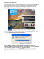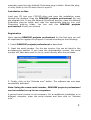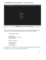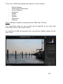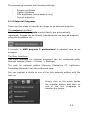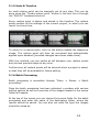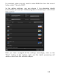
1
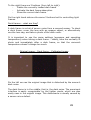
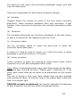
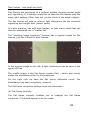
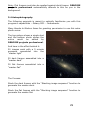
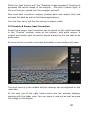
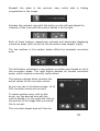
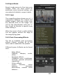
DENOISE projects professional
User Manual
Dipl.-Math. Michael Piepgras
Installation on Windows
The start screen for the installation will normally be automatically displayed.
If the auto-start function of your CD/ DVD drive is deactivated, open the
start screen manually by going to My Computer, double clicking on the
CD/DVD drive symbol and then “Starter.exe” or “Starter”.
Once you are at the CD start screen, choose your language and then click
on “Install DENOISE projects professional”.
Choose German, English or French as setup language and follow the
installation assistant’s instructions. During the installation, you will be asked
if you would like to install the Adobe® Photoshop plug-in.
If you agree to this, you can use DENOISE projects professional as a
plug-in for Adobe® Photoshop. Alternatively, the plug-ins can also be
2
manually copied into the Adobe® Photoshop plug-in folder. Select the plugin entry folder in the CD start menu to open it.
Installation on Mac
Load your CD into your CD/DVD drive and open the installation menu
through the desktop. Drag the DENOISE projects professional file into
the program link. To use the Adobe® Photoshop plug-ins, open the Adobe®
Photoshop plug-ins folder and copy the appropriate plug-ins into your
Photoshop plug-ins folder. You can now use DENOISE projects
professional to edit your photos!
Registration
Upon opening DENOISE projects professional for the first time you will
be requested to register the program. Proceed according to the following:
1. Install DENOISE projects professional as described.
2. Input the serial number. For the box version, this can be found in the
accompanying booklet. If you have the downloadable version, the serial
number will have been sent to you by email directly after the purchase.
3. Finally, click on the “Activate now” button. The software has now been
successfully activated.
Note: Using the same serial number, DENOISE projects professional
can be installed on up to two computers.
A second serial number is not necessary. For an additional installation on a
different computer, enter the serial number and then click on “Activate
now”.
3
1. Image Noise - what is it?
Image noise in digital image production occurs in many different ways.
One example is so-called low noise, a sensor-dependent noise caused
by CDD and CMOS sensors. An additional multiplier is the reading
strength in digital cameras, which produces read noise.
Hot pixels can appear with increased age of the camera or through
image sensor manufacturing defects. These are individual pixel sensors
that were incorrectly manufactured or have a significantly higher light
sensitivity compared to the pixels around them.
It generally the case, that the higher the ISO Number (the camera’s
exposure setting) is, the more visible the noise will be.
What types of image noise can you reduce or remove with DENOISE
projects professional?
-
Chroma Noise (colour noise)
(Filter: Denoising - colour)
-
Luminance Noise (bright noise)
(Filter: Denoising - HD)
-
Hot pixels
(Filter: Hotpixel noise suppression)
-
Salt & Pepper (individual defective pixels)
(Filter: Hotpixel noise suppression)
-
Gaps
(Filter: Denoising - fill gaps)
-
Banding
(Filter: Denoise - banding)
-
Colour Clouds
(Filter: Denoising - colour clouds)
In most cases, the different types of image noise do not appear
individually, but rather in a mixed form. This is why it is important to
remove noise in the correct order, as shown above, to obtain optimal
results.
4
2. DENOISE projects professional – the start screen
The start screen for DENOISE projects professional is simply set
up.
You can find the main menu and tool list at the top edge of the screen.
This tool list includes the following functions (from left to right):
-
Image data browser
-
Load image
Stacking image sequence
Open project
-
Batch processing
-
Load sample 1
Load sample 2
Load sample 3
Alternatively, photo files can also be dragged and dropped into the
program. They will be automatically uploaded.
5
3. The Work Area
As soon as the photo file has been uploaded to the program, the virtual
work area will open.
This interface is divided into four main areas:
-
Menu and tool list (top)
Presets (left)
Image (middle)
Noise removal and expert mode (right)
You can remove the individual sections of the work area from the
interface and place them in other spots or on another window.
To reset the work area to its original layout, go to “View” in the main
Menu and select “Restore window defaults”.
3.1 Tool List
The tool list is divided into two sections. The left side refers to the
program’s control functions and the right tool list manages the image
overview.
The functions in the tool list (from left to right):
-
Start (new project)
-
Save current project
-
RAW-processing
Post processing
-
Save image
Transfer image to selected projects program (Selection in the
list to the right)
-
Export image to external program
Exposure bracketing and transfer to external program
6
-
Create restore point
Timeline
-
Histogram
Certain primary functions of DENOISE projects professional will
now be explained in greater detail.
3.1.1 Uploading and Saving Files
To load images into the program, you can either drag and drop them,
use the button in the tool list in the start menu or use “File”, “Load
image”.
When importing a file into the program with drag and drop, the image
data browser will automatically open to display the folder’s contents
with preview images.
A double click on the preview in the image data browser directly loads
the file.
Photo formats:
DENOISE projects professional
can upload all photo formats. This
also includes camera RAW images
from various manufacturers.
If a RAW file is available, you should
always use it. This file type contains
considerably more information than,
for example, a JPEG file.
7
3.1.1.1 Stacking Image Sequence – Noise stacking
The stacking image sequence feature is based on the so-called Signal
to Noise Ratio (SNR).
Here a sequence of images of a subject, taken with the most similar
conditions as possible, are assembled as one image with reduced
noise.
The image noise is reduced by the ration 1:“Root of the number of
photos”.
For example, if you take a photo with an ISO 12800, you can expect a
high amount of noise.
Using a tripod, consecutively take the same shot 4x and lay them one
on top of the other with image sequence stacking. You will obtain an
image with 1:”the root of 4” = 1:2, i.e. half of the original noise.
You can reduce this noise further with more photos. With 100 shots,
your image at 12800 would only have 1/10 (one tenth) of the initial
noise.
The following comparison is a practical example of stacking 10 images:
Single image
Noise stacking with 10 images
8
The image sequence stacking function stacks three different types of
images on the same spot: light frames, dark frames and flat frames.
Further information on these topics can be found in the chapter
“Correction Images”.
3.1.2 Projects
A project includes the entire work in progress for the subject at hand.
The current state of the project can be saved (File -> Projects -> Save
project), and you can return to it and continue from this exact point at
a later time.
In addition, the list of steps will be saved so that the work history can
be accessed later.
3.1.3 RAW Module
The RAW module is a RAW processor integrated into the program.
Simply click on the RAW symbol in the tool list to access this function.
9
There are 9 different adjustment options in this module:
-
White balance
Denoising & Sharpness
Colour Balance
Exposure
Detail
Colour
Palette
Distortion
General
Note: Editing is equally as possible with JPEG and TIF files.
The processing step for your image can be applied at any time and
more than once in the work history.
An example of RAW processing from a previously loaded image can be
seen here:
10
The processing includes the following settings:
-
Enhance brilliance
Lighten shadows
Dim brightness (more detail in sky)
Correct distortion
3.1.4 External Programs
There are two steps to transfer an image to an external program.
The projects Interface:
All programs in the projects product family are automatically
registered. Images can be directly transferred to the desired program
using the dropdown list.
A transfer to HDR projects 3 professional is selected here as an
example.
The Main Interface:
The main interface for external programs can be configured solely
through settings (Menu -> Extras -> Settings).
The path for external editors (General, Photoshop CC, Lightroom,
Photoshop Elements) can be configured here.
You can transfer a photo to one of the four external editors with the
tool list:
Simply click on the arrow beside
the transfer button and then on
one of the four programs to
transfer the image.
11
3.1.5 Undo & Timeline
An undo-restore point can be manually set at any time. This can be
done using the “Create restore point” button in the tool list or through
the “Shift+Z” keyboard shortcut.
Every restore point is shown and stored in the timeline. The restore
points contain all the settings of the current project, to which you can
revert to at any time.
To return to a restore point, click on the button beside the respective
image. The restore point will then be recovered and automatically
applied upon demand (provided changes have been made since).
With this method, you can switch at will between your restore points
and retrieve previous steps at any time.
Furthermore, all restore points will be secured when a project is saved,
so that they will be available for future editing.
3.1.6 Batch Processing
Batch processing is accessible through “Menu -> Extras -> Batch
processing”.
Once the batch processing has been activated, a window with various
setting options as well as a preview of the images located in the source
folder will appear.
At the top of the screen you can choose the source folder for the batch
processing and enter the name of the destination folder, where the
results should be saved. You can also set what file type the images
should be saved as.
12
For example, when you only want to select RAW files from the current
folder, select “Camera RAW”.
In the editing settings, you can choose if the denoising should
automatically proceed (in 3 different grades of intensity) or use a fixed
filter instead.
After you have arranged all the settings accordingly, click on the
“Start” button at the bottom right and the batch processing will
remove noise from the selected images.
13
3.2 Presets
Presets are located on the left side of the program’s interface and are
divided into 6 different categories.
The first two categories, Noise suppression and Sharpening levels,
include presets for different ISO ranges, from ISO 50 up to ISO
2000000.
The JPEG, RAW, Mobile and Web categories
customized denoising and optimizing presets.
contain
specially
The category All simultaneously displays all of the presets and the
Custom category shows only the presets that you have made yourself.
3.2.1 Favourite System
The favourite system allows preferred presets to be marked as
favourites.
To do so, click on the star beside the preset’s preview image.
Once you have selected one or more favourites, the favourite category
will be activated. With a single click on the favourite category, you are
presented with all of your favourites.
3.2.2 Import & Export
The import and export functions are used to transfer presets. These
data will be saved as .ini files.
The export button allows you to save the presently selected presets.
The import button lets you import the previously exported presets at a
later time.
This way you can save your work or exchange presets with other
users.
14
3.2.3 Search Field
You can enter any desired text you wish to search in the search field,
located directly underneath the import area. All of the presets will
then be searched by name based on the entered text and displayed
accordingly.
For example, if you are looking for a preset with a soft look, simply
enter soft.
A list of previously searched terms can be found to the right of the
search box.
3.3 Denoise Section (Noise Properties)
The denoise section on the right side
of the program’s interface is the
core
of
DENOISE
projects
professional. Here you will find
details about the noise properties,
can activate various processes,
display colour channels, etc.
This topic will be introduced in detail
in the following section.
Additionally, this group of functions
provides the option of integrating
corrective images such as dark
frames and flat frames into the
current project.
A more specific explanation can be
found in section 3.3.7.
15
3.3.1 ISO Display
There are three ISO displays in the first segment of the denoise
section.
The above display indicates the ISO sensitivity of the original
exposure, the example here being at “Image ISO Value: ISO 1600”.
Directly below are the mathematical analyses of the image noise.
Source image noise:
Here the noise in the image will be measured by a special process and
assigned an average ISO sensitivity, for example “Source image noise:
2.3% ISO 400”.
The analysed image then contains 2.3% noise.
Note: Don’t be disturbed by the fact that the ISO value of noise
analysis does not match the ISO number of the shot. Camera sensors
react differently to the set sensitivity. This is how noise properties are
distinctly distinguished between a D810 and an EOS7D Mark II.
The image noise must be based on an analysed ISO value, which will
be displayed here.
Resulting image noise: Directly under the source image noise you will
find the analysed noise value for the result image, in the example here
“Result image noise 0.5% ISO 80”.
The ISO value can be reduced from ISO 400 to ISO 80 with the noise
removal.
Note: Be careful not to denoise the images too much, since the natural
look can be lost. A result image noise of 0.5% to 1.0% is usually
sufficient in most cases.
16
3.3.2 Image Noise Measurement
Image noise is analytically determined by a process which scans and
categorizes the entire image for consistent surfaces without actual
image data.
Image noise is measured in this “pure” type of noise.
Since measuring image noise throughout the entire image
automatically occurs, a manual search for potential image noise is not
necessary.
Click on the “Show measured noise areas” to display this calculation
section.
Note: You cannot access the automatic noise removal while the
calculation window is open. Simply deactivate the display.
3.3.3 Automatic Noise Removal and Optimization
Automatic Denoising
The automatic noise removal function analyses the current image and
looks through the denoising presets for the optimal filter.
Three different degrees of intensity are available with this automatic
process.
The balance option will be automatically applied after loading the
image.
17
If you want an image with a softer or grainier noise removal result,
you can adjust the automatic preset with one click on the
corresponding photo.
Automatic image optimization
Once the noise removal has taken place (which automatically occurs
following the initial uploading) you can select the “Automatic
denoise/optimize” button.
One click selects the appropriate automatic noise removal optimizing
filter from the default Sharpen category.
Manual Noise Removal
Directly to the right of the automatic sharpening and optimizing is the
manual noise removal interface. Clicking this mode will temporarily
deactivate the automatic system and you receive a pre-made preset
with all of the important noise removal and sharpening effects.
You can directly edit this preset in expert mode.
3.3.4 Denoise Colour Space
The denoise colour space is a distinctive feature of DENOISE projects
professional.
This colour space allows you to improve the noise removal quality of
specific tones, with reduced loss to other colours.
18
There are a total of 10 different colour spaces available (from left to
right):
-
Colour space automatically selected based on image
Brightness sensitivity appropriate for the human eye
Neutral grey
Red dominant
(e.g. rose blossom)
Orange dominant
Yellow dominant
Green dominant
(e.g. landscape)
Turquoise dominant
(e.g. sky)
Blue dominant
(e.g. water)
Violet dominant
Let’s look at an example of a red rose:
We see the original image on the left side with ISO 25600, an
automatic noise removal with the neutral grey colour space selected
and the image on the right with the red dominant colour space.
You can distinctly see the improved detail in the inside of the rose in
the shot on the right.
Note: Choose the noise removal colour space based on the area of the
subject that you want to highlight.
19
3.3.5 Channel Displays
The channel displays serve as the optical analysis of your image.
Note: Make sure that “Real-time calculation” is active in the tool list, so
that the display will be refreshed.
There are 7 different channel displays to choose from:
(a) Full colour view
This display shows an image with all of the colour channels:
red, green and blue.
(b) Luminance view
The brightness of the image (depending on the selected noise
removal colour space).
(c) Chromatic view (Colour map view)
With the colour map view, you will very quickly see if your
subject contains colour noise. If the colours are very
“unsettled”, you should use the Denoise – colour at a high
intensity.
(d) Red channel
With the red channel, you can see brightness of the red
portion of the image.
(e) Green channel
With the green channel, you can see the brightness of the
green portion of the image.
20
(f) Blue channel
With the blue channel, you can see the brightness of the blue
portion of the image.
(g) Difference between the source and resulting images
The difference image shows you the noise removal from the
image.
Now what counts: the fewer details of the original image that
can be seen in the difference display, the better the noise
removal (the fewer details of the image were influenced).
Once the difference view has been activated, a controller will
appear where you can increase the contrast of the difference
display. For images with minimal image noise, the difference
is difficult to notice – in this case, simply increase the
difference contrast.
A comparison of the different views of the image clarifies the functions.
Original image – Luminance view – Chromatic view
It is clear to see the distinct noise in the chromatic view on the right
side, which indicates colour noise.
Note: Activate the measurement field to also display the colour noise
as a numerical value, here 30.8% colour noise.
21
The brightness noise in the luminance view in the middle is
significantly less noticeable.
Red channel – Green channel – Blue channel
The comparison of the noise properties in the colour channels provides
important information for choosing the correct noise removal colour
space.
In this section, prominent noise can be seen in the red and blue
channels. The green ratio contains relatively little noise.
Putting this information together indicates that a purple colour space
should be applied for the intense red and blue noise.
Note: What colour space should I use for which colour channel noise
combinations?
Red & Green
Red & Blue
Green & Blue
= yellow colour space noise removal
= purple colour space noise removal
= turquoise colour space noise removal
22
Original image – Denoised image – Difference view
The view of the light noise around the string of lights in the denoising
view (here with a difference contrast of 150%, i.e. enhanced) shows
that practically only noise was removed from the image.
This can be confirmed by the fact that basically no details can be seen
in the difference view.
3.3.6 Restricting areas
Area restriction allows you to limit the noise reduction to a specific
area.
In this case, there is a more obvious direct comparison between the
original image and the result after noise removal.
23
Also, you can save valuable time by restricting areas in the manual
noise removal setting. The smaller the noise reduction area, the faster
the calculation.
If you are satisfied with the results, reactivate the denoising for the
entire image.
The 8 restriction modes (from left to right):
-
Full image (entire image)
-
Diamond
Elliptical
Rectangle
-
Left side
Right side
Horizontal middle
Vertical middle
Once area restrictions have been activated, a controller will appear
where the size of the area can be regulated.
24
3.3.7 Correction Images
The correction image option
offers you the opportunity to
remove noise in a professional
manner with the help of
correction images.
Compared
to
classical
mathematical noise removal,
this method is an exact
procedure.
DENOISE
projects
professional
fundamentally
supports the application of socalled dark frames and light
frames.
The individual correction image buttons:
The buttons are divided into three categories.
In the middle there is the “Upload a correction image” function. This
button is active until two images have been uploaded. The software
automatically recognizes if the uploaded file is a dark or light frame.
25
To the right there are 3 buttons (from left to right):
Delete the currently loaded dark frame
Activate the dark frame absorption
Show the current dark frame
On the right hand side are the same 3 buttons but for controlling light
frames.
Dark frames – what are they?
A dark frame is a shot of sensor noise from a covered sensor. To shoot
a dark frame, cover the lens with an opaque object, or alternatively
use the lens cap, and take a photo of the dark noise.
It is important to use the same settings (exposure and operating
temperature) when taking a dark frame – ideally, take the normally lit
photo and immediately after a dark frame, so that the camera’s
temperature doesn’t change too much.
Original image – Dark frame – Calibrated image
On the left we see the original image that is disturbed by the sensor’s
dark noise.
The dark frame is in the middle, that is, the dark noise. The prominent
interface is easily recognizable by the lighter pixels, which are also
easily seen in the original image. This disturbance is usually caused by
a sensor micro defect.
26
The picture on the right is the corrected (calibrated) image, with help
from the dark frame.
There are 4 parameters for dark frame correction settings:
(a) Iteration
Iteration shows the number of cycles of the dark frame correction
algorithms. These correction processes work very accurately. A high
iteration value improves the precision but probably generates a softer
result.
(b) Threshold
The threshold determines the minimum brightness of the dark frame,
so that a correction for the respective pixel can occur.
(c) Correction radius
Use the correction radius to select the pixel area in which the
correction should take place.
A radius of 1 uses an area of 1 pixel, so in total 3x3 pixels, a radius
generates a correction matrix of 7x7 pixels.
(d) Colour correction
Colour correction is option for reducing so-called colour clouds. Colour
clouds are very soft and widespread colour noise.
Note: Often in astrophotography many dark frame shots will be taken,
which are then summed up into a “Master dark”. Definitely 50, if not
more, dark frame shots can be taken to be assembled into the master
dark.
The rule of thumb is that more dark frames than normally exposed
shots should be taken, so that the noise in the master dark is less than
that in the master light.
DENOISE projects professional can directly assemble the sequence
of dark frames for you with the batch processing function.
27
Flat Frames – and what are they?
Flat frames are exposures of a uniform surface showing sensor spots
and vignetting. It is thereby important to take the flat frames with the
same optic settings (filter, lens etc.) as the shots of the actual subject.
The flat frames will help to remove light distortions like the camera’s
vignetting and caught dust (sensor spots).
It is also practice, like with dark frames, to take many shots that can
then be assembled into a “master flat”.
The “stacking image sequence” function has a special modus for flat
frames, just like it does for dark frames.
In the original image on the left, a light interference can be seen in the
upper left half.
The middle image is the flat frame (master flat) – which also clearly
shows the shadowing defect in the brightness.
On the right side we have the flat frame calibrated result. The
disturbance has been completely removed.
The flat frame correction settings have one parameter:
(a) Flat frame intensity
The flat frame intensity enables you to readjust the flat frame
correction, if it should appear to be too weak.
28
Note: Flat frames must also be applied against dark frames. DENOISE
projects professional automatically attends to this for you in the
background.
3.4 Astrophotography
The following example is meant to optically familiarize you with this
program’s capabilities – Galaxy M31 – Andromeda.
Many thanks to Markus Janes for granting permission to use this astro
photo series.
The top picture shows a single shot
and the bottom photo shows the
entire
result
as
edited
by
DENOISE projects professional.
And here is the effort behind it:
20 images each with a 5 minute
exposure assembled into the
“master light”
20 dark frames assembled into a
“master dark”
30 flat frames assembled into a
“master flat”
The Process:
Stack the dark frames with the “Stacking image sequence” function to
generate the master dark.
Stack the flat frames with the “Stacking image sequence” function to
generate the master flat.
29
Stack the light frames with the “Stacking image sequence” function to
generate the actual image of the subject – this shot (master light) is
the one that you upload into the program yourself.
Now load both correction images (master dark and master flat) and
activate the dark as well as flat frame applications.
You can then carry out the fine tuning in expert mode.
3.5 Scratch & Sensor Spot Correction
Scratch and sensor spot correction can be found on the right hand side
in the “Finalise” window, down at the bottom, with good reason. A
scratch and sensor spot correction should always be the last task to be
performed.
As soon as the correction has been activated, a new window will open:
The work area is in the middle and the settings can be adjusted on the
right side.
At the very top of the right hand column are the preview settings,
starting with the radar view. You can zoom in and out as well as move
the image in this display.
30
Beneath the radar is the contrast view, which aids in finding
irregularities in the image.
Activate the contrast view with the button on the left and adjust the
intensity of the view with the control beside it to the right.
Both of these buttons respectively activate and deactivate displaying
corrective areas (left) as well as the correction area targets (right).
The two buttons in the section below effect the complete correction
area.
The left button calculates a new optimal correction spot based on all of
the correction areas. The right button deletes all current correction
areas, which requires a security confirmation.
The bottom settings block contains the
actual values of the correction areas:
As you can see in the above image, 14 of
200 correction areas are set here.
To select another area, click on the
brush, set the desired size with the
control beside it on the right and click on
the portion of the image that you would
like to correct.
The correction target area will then be
31
automatically found, accordingly placed and displayed to you.
You can shift this target area with your mouse if you are not content
with the automatic proposal.
The “Size” control under this section enables modification of correction
area. Simply click on the correction area and adjust the size with the
controller.
The bottom left button allows you to switch the currently selected
correction area back to the automatic mode, as long as you have
modified the area.
With the bottom right button, you can delete the currently active
correction area.
The keyboard configuration for this window can be found in the
“Keyboard Shortcuts” chapter.
32
3.6 Expert Mode
Expert mode serves to fine tune your
images. After you have found an
automatic noise removal setting, you
can adjust all details in expert mode.
3.6.1 Lupe
The magnifying glass shows you a 1:1
comparison between the original and
edited images. Hold your cursor over
any desired point on the image. You
can fix the magnification with the “L”
key (Lock) to monitor a specific area
while editing it.
When the area is fixed, a white dotted
line will appear around the edge of
the magnifying glass.
3.6.2 Post-Processing Effects
The list of available post processing
effects (filters) includes all of the
tools used to assemble the presets.
Different types of effects can be found
here:
-
-
-
Edge effects
Denoise, sharpen, erode,
dilate...
Exposure effects
Gradation curve, brightness,
contrast, gamma correction,
vignetting...
Colour effects
Colour
intensity,
colour
balance,
chromatic
aberrations, manual white
balance...
33
-
Soft focus effects
Smooth colour tone, soft focus
The so called context menu can be opened with a right click. Here you
can disable individual effect groups to get a better overview of the
effect of a singular category.
The most important effects for denoising your images are with the
edge effects, notably all effects beginning with “Denoise -” here. (An
exact overview can be found in Chapter 1.)
If you want to add a post processing effect to those of the current
filter, double click on the list entry and the effect will be automatically
added to the end of the “Effects you have selected” section.
3.6.3 Effects you have selected
The list of effects you
have
selected
represents the entire
calculation process for
the current image.
The effects can be
turned on and off by
selecting the check
marks
beside
the
names.
A small icon to the
right of the checkmark shows you if a layer effect (light bulb) or
selective editing (red-green circle) is active.
If you have an effect that you would like to have at a different position
in the order of edits, simply use the mouse to pick it up and slide it to
the desired place. The result will be automatically refreshed.
Note: The order of the effects has a crucial influence on the results,
depending on the combination. If you want to reduce the chromatic
aberration for example, you should always do so before enhancing
colour intensity. By boosting the colours first, the aberration will also
be amplified.
34
A right click on the effects you have selected menu will open a context
menu with the following functions:
-
Activate effect
Activate all effects
Activate all other effects
Activate this effect only
Deactivate all effects
Duplicate effect
Restore effect
Send to top of list
Send to end of list
Delete effect
Remove all the effects
As soon as you have selected an effect in this field, the settings for the
effect at hand will appear directly below this area.
3.6.4 Parameters – layer methods
At the very beginning of the parameter section for the selected effect
(here Denoise – colour) is the tool to set the calculation method for
this effect layer.
The calculation method for this effect layer can be chosen in the
dropdown menu. Numerous variations are available here, starting with
simple methods like brighten and darken to colour burning and linear
dodging.
Note: Feel free to try out these techniques – the layer calculations can
be restored back to normal at any time when you deactivate them.
On the right side, the opacity of the effect layer can also be adjusted.
If an effect is too strong for you, you can reduce the opacity some until
you are pleased with the result.
35
3.6.5 Parameters – Selective Editing
Underneath the layer calculations are the buttons for selective editing.
From left to right:
-
Open selective editing
-
Copy selective areas to the clipboard
-
Copy selective areas from the clipboard into the currently
selected effect (existing areas will then be replaced)
-
Delete all selective areas from the selected effects
Selective areas present a special feature. You can set up to 32
selective layers for every effect layer.
Selective areas can be either positive (green) or negative (red), and
you can be mixed according to your preference.
What establishes a positive selective area?
A positive area allows you to specify an area of the effect layer to be
modified while the rest of the image remains unaffected.
And what establishes a negative selective area?
Negative selective areas do the exact opposite. This effect excludes
selected areas from the current effect layer.
A new window will open once the selective editing has been activated.
Here you can fix the selective area for the chosen effect layer (here
colour intensity).
36
The below tool list enables the creation of areas and the generation of
masks using these areas.
The individual functions are (from left to right):
-
Add positive selective area
Add negative selective area
-
Inverts the selective areas (positive becomes negative and
vice versa)
Duplicate currently selected area
Delete currently selected area
-
Invert all selective areas
-
Deactivate the display of selective areas
Show only the selected selective areas
Show all selective areas
37
-
Select next selective area
Select the previous selective area
In the example image we see a positive selective area over the top of
the tree for the colour intensity effect.
The area can be shaped however you like. Grab the marked edge of
the area with your mouse and move the area’s borders into your
preferred form.
To move the entire area, simply grab the depicted right corner and
move the area to where you want it.
Once a selective area has been selected, the three controls on the top
edge of the window will be activated, giving you with additional
influence on the image.
Curvature:
Adjust the curvature of the selected area from a hash (controller to the
left) to a rectangle (controller to the right).
Sharpness (edge definition):
Adjust the edge definition of the selective area from soft (controller to
the left) to sharp (controller to the right). If you want to mask a
window,
for
example,
select
curvature=100%
and
edge
definition=100%
Strength:
The intensity sets the opacity of the selective area at hand. This way
you can somewhat reduce the effect.
When you are finished setting the selective areas, click “Exit”. The
adjustments will be applied and the results refreshed.
38
3.6.6 Parameters – Set values
There are different types of
data that you can modify
within the parameters of an
effect layer.
The
“Intensity”
control
parameter can be seen here
as an example.
You can either directly adjust
the control parameter with
the controller or by inputting
a numerical value.
Double
clicking
the
controller’s
handle
will
always reset the conditions
back
to
their
standard
values.
Directly below the controller
is a masking curve with a
few
presets
above
the
displayed curve.
You can automatically create
brightness masking with the
masking curve. Move the control points on the brightness curve to your
preferred levels. The top edge has a 100% effect intensity while the
bottom edge has a 0% effect intensity.
You can see a real time display of the curve’s masking while moving
the control points. The effect shows a high intensity in bright areas and
a lesser intensity in darker areas.
39
4. Keyboard and Mouse Shortcuts
General Functions
Function
Windows
Mac OS
CTRL + N
CTRL + SHIFT + O
CTRL + S
CMD + N
CMD + SHIFT + O
CMD + S
L
L
F4
F4
CTRL + H
CTRL + E
CTRL + F
CTRL + F / ESC
CMD + H
CMD + E
CMD + F
CMD + F / ESC
Call up home page
Help
About DENOISE
projects professional
@
F1
SHIFT + F1
@
F1
SHIFT + F1
Stacking
Settings
Timeline on/off
Save project
CTRL + B
CTRL + P
CTRL + T
SHIFT + Z
CMD + B
CMD + P
CMD + T
SHIFT + Z
Double click
Double click again
Right click
Double click
Double click again
Right click
New project
Upload image
Save result image
Lock magnifying glass
RAW processing
Show histogram
EXIF information
Full screen view
Quit full screen view
Image to fit
Image to fit 1:1 view
Quick comparison
40
Selective Editing
Function
Windows
Mac OS
Move selected area
Arrow keys
Arrow keys
Select previous field
Select next field
Delete current
Image up
Image down
Delete
Image up
Image down
Delete
1
2
1
2
3
3
Function
Windows
Mac OS
Move selected
correction area
Enlarge selected
correction area
Reduce selected
correction area
Arrow keys
Arrow keys
+
+
-
-
Select previous
Select next
Delete current
Image up
Image down
Delete
Image up
Image down
Delete
N
C
N
C
Deactivate mask display
Display selected mask
areas
Display all mask areas
Screen & Sensor Spot Correction
Set new correction area
Activate all correction
areas
41
Hotline/Support
If you have questions regarding the installation, problems or errors of the software, please
contact the FRANZIS customer support team.
E-Mail: [email protected]
Phone (Monday to Friday 12am to 6pm): +49 (0)180 30 02 644
(0,09 EUR/minute from German landlines, prices from mobile phones might vary)
Fax: +49 (0)180 300 26 45 (0,09 EUR/minute from German landlines, prices from
mobile phones might vary)
Please understand that your questions can only be answered directly by FRANZIS customer
support. This is to give us the opportunity to constantly enhance our customer service for you
and to make sure that you receive only the most qualified answers to all of your questions as
fast as possible.
This is how our customer support works best:
Please have the most important details about your computer and about our product at hand
when you call our customer support. These include:
• Name of the product
• Product ISBN (which you can find on the back of the packaging, above the easy to
spot barcode).
• Operating system of your computer
• Technical details of your PC including all your peripheral devices
Copyright
Franzis Verlag GmbH has prepared this product with the greatest possible care. Please read
the following conditions:
All the programs, routines, controls, etc., contained in this data media or within this download
are protected by their respective authors or distributors as mentioned in the respective
programs. The purchaser of this data media or of this download is authorised to use those
programs, data or data groups that are not marked as shareware or public domain for his/her
own purposes within the provisions of their designated use. He/she is authorised to use
programs or parts of programs that are marked as shareware, freeware or public domain
within the restrictions given by the respective programs or parts of programs. A reproduction
of programs with the intent of distributing data media containing programs is forbidden.
Franzis Verlag GmbH holds the copyright for the selection, arrangement and disposition of the
programs and data on these data media or these downloads.
The data and the programs in this data media or within this download have been checked with
the greatest possible care. Considering the large quantity of data and programs, Franzis
assumes no warranty for the correctness of the data and a flawless functioning of the
programs. Franzis Verlag GmbH and the respective distributors do not undertake neither
warranty nor legal responsibility for the use of individual files and information with respect to
their economic viability or their fault-free operation for a particular purpose.
Additionally, there is no guarantee that all the included data, programs, icons, sounds and
other files are free to use. Therefore the publisher cannot be held liable for a possible breach of
third party copyrights or other rights.
Most product designations of hard- and software and company names and labels mentioned in
this product are registered trademarks and should be treated as such. The product
designations used by the publisher are basically as the manufacturer describes them.
© 2015 Franzis Verlag GmbH, Richard-Reitzner-Allee 2, 85540 Haar, München
42