1
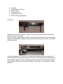
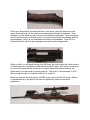
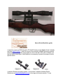
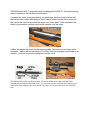
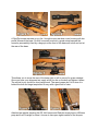
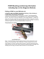
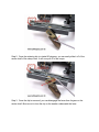
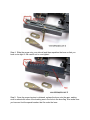
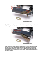
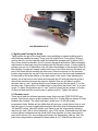
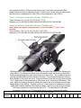
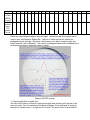
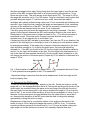
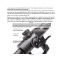
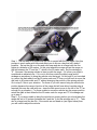
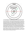
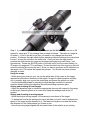
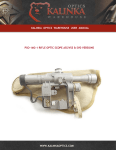
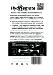
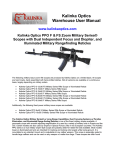
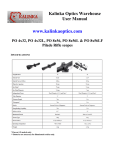
Kalinka Optics Warehouse
User Manual
www.kalinkaoptics.com
-
Kalinka Optics Presents:
Installing a side plate on your SKS for mounting a
rifle scope.
Mounting your SKS with a scope.
Adjusting a side mount to securely fit your installed
side rail.
Zeroing Information for Dragunov scope reticules.
Mounting your SKS is easy. It takes a basic level of mechanical aptitude, some
simple tools and attention to detail. To mount your SKS you will need the Kalinka Optics
Warehouse Universal AK/SKS/SVD Side Plate, Undrilled which can be found in the
Mounts & Rings section at www.kalinkaoptics.com. Once you have attached the plate to
your SKS you can use any AK, SKS/SVD or Russian Small Arms mount including all of
our side mounts and the POSP/PSO series of scope. Mounting your SKS by drilling and
tapping a plate is the absolute only way to mount an SKS, using a receiver cover is
strictly for those who don’t know any better.
This guide has a general manual, then a step by step walk-through by Ernie
Burdick and then a commentary with helpful tips by Roman Polaski. Special thanks to
these two gentlemen for allowing us to reprint their letters.
Due to the fact that there are so many variants of the SKS rifle, this procedure is
provided as guide and reference tool. We hope that the information contained herein is
helpful in mounting your SKS. Remember it is only a guide and if in doubt, you should
use the services of a professional gunsmith. Kalinka Enterprises, LLC is in no way liable
for the use or misuse of this information.
Recommendations for mounting the scope plate:
1. 13/64 High tensile strength Drill
2. ¼-28 High tensile strength Tap
3. Drill Press
4.
5.
6.
7.
8.
9.
C Clamps
Small Rotary cut-off tool
Center Punch
Countersink Bit
A coping or pull saw
220 and 120 grit sandpaper
First Step:
I drilled the holes 2 5/8 on center, 2 3/8 O/C from the end to the first drill hole and 3/8
O/C from the top of the body.
NOTE: The above picture was provided to show the whole layout but to ensure a proper
alignment I recommend clamping the mount plate to the body and then drill, countersink
and tap the holes.
It will be necessary to cut your stock, to determine the dimensions, use a pencil and
draw a along the bottom edge and right and left side of the mount followed by drawing a
line along the edge of the stock. Remove the plate and measure the distance between
the two marks. These dimensions will provide you with depth of cut necessary to allow
proper fit.
Check your dimensions, and draw the lines on the stock, verify the dimension once
again, place the body into the stock and compare the markings for alignment. Now
proceed to cut the small amount of wood to complete the application. Upon completion,
verify fit with the body, stock and mount, if it is a good fit proceed with sanding with fine
grit sandpaper, if the fit is too small sand with heavy grit sandpaper. Once the fit is
confirmed finalize with fine grit sandpaper and stain or paint as applicable.
When you drill, you will break through the SKS body, be sure to grind the inside surface
to ensure there is no interference with the bolt and bolt carrier. Also keep in mind when
you mount the plate that the screws do not extend beyond the interior surface, you
might need to cut the screw to ensure proper fit. This is why I recommended ¼-28 to
allow enough threads on the plate and body for a tight fit.
Below you can see the final results, A POSP scope mount with a 4X32 scope. Based
on the placement on the plate it will allow for adjustment based on the user’s
preference.
Here is Ernie Burdick’s guide:
I wanted to scope my SKS rifle with a PO 4x24 Russian scope (figure 1) that I already
had from Kalinka Optics. I didn't like most of the currently available mounting systems
which seem to me to put the scope either too far to the rear of the rifle or directly over
the bolt where some type of shell deflector is necessary to protect the scope from the
ejected cases.
I wanted a Russian mounting system. I found what I wanted at Kalinka Optics
Warehouse at www.kalinkaoptics.com in the rings and mounts section. It is an
SVD/SKS mount with 1" rings and a side mounting plate for $24.97. The side mounting
plate is attached to the left side of the receiver.
I mounted the scope in the permanently mounted rings, slid the mount onto the side
plate and locked it down with the lever. Next I held it in place on the rifle to check the
eye relief of the scope and marked the stock once it was good. I then transferred the
marks to the receiver and then removed the receiver from the stock.
I drilled and tapped two holes for the mounting plate. The holes are very large in the
side plate, I had to drill and tap using a 10-24 tap. Once the side plate is mounted to the
receiver, I next had to remove some wood from the stock.
The MIT machinist reference describes tapping as -
The finished rifle looks very Russian now. The scope mount easily comes off and makes
cleaning and storing the rifle much easier. You can even take the scope off at the range so you
can load up with stripper clips. Just remount the scope, lock it down and it always returns to
zero.
A Red-Dot scope was next on my list. I bought a new rear dust cover housing with low
profile Weaver style base. On this I mounted a red dot, a great setup because the
mount is permanently fixed by a large pin at the front of the base and a bolt and nut at
the rear of the base.
This allows you to move the rear of the base right or left to correct for gross windage.
Once you have your alignment set, apply a little loc-tite on the bolt and tighten it down.
The red-dot is my choice for short range work. The spent cases don't hit it since it is
behind the bolt and target acquisition is easy with a good field of view.
Attached are photos showing the PO 4x24 scope and Red-dot scope plus my Williams
peep and front Firesight for when I choose to use open sights instead of the scopes.
Roman Polaski’s Yugoslavian SKS w/ Kalinka Optics POSP 4x24 SVD/SKS
mounted using a Kalinka Optics AK/SKS/SVD Universal Side Plate.
I purchased a few of the AIM Yugos. This one was an all matching $89 model. I'm a
C&R and I didn't want to damage a good rifle. This one is in about 85% condition, good
bore and ok metal. I also didn't want to damage the stock as it, too, had matching
numbers. So, I purchased a spare stock, stripped, altered, cleaned, and refinished it.
After cutting the stock to accommodate the mounting plate, it took a little time to get the
wood on the left side of the stock thin enough to slide the scope on but you can hardly
tell.
I will tell you this also. I put my laser bore sighter in it this evening to see how the scope
tracked with the rifle. I am extremely pleased to report that the scope was dead on! I
couldn't believe it myself. I'm going to site it in this week at the range and expect to only
crank in a little "up" at 100 yards. From there I'll use the scope to make distance
adjustments.
These scopes are an incredible buy. I'm going to order another in the near future just to
have for an AK47 that I'm planning on adding to my MBR semi-auto collection. They are
rugged, accurate, extremely well built and above all, reasonably priced.
BTW, the mounting plate was drilled and tapped for three 6/32 x 1/8" screws. I recessed
the flat head screws into the plate and drilled and tapped the side of the SKS wall. If I
decide to remove the scope and plate and return the original stock, the holes will be
below the skirt of the stock keeping the rifle looking 100% stock. Overall, I'm a happy
camper and hope you enjoy the photo. Feel free to use it as much as you'd like if you
find it attractive.
Roman J. Polaski
Enfield, CT
PS I'm going to build a cheek piece for the stock although I can shoot it easily the way it
is. The cheek piece will make it even easier, however.
RJP
POSP Mounting and Zeroing Information
including tips on the Dragunov Reticule
Putting a POSP on your SKS side rail.
LOCKING CLAMP ADJUSTMENT REQUIRES NO SPECIAL TOOLS OR SKILLS,
PLEASE READ THE INTSRUCTIONS BELOW
Locate the locking clamp assembly, (see picture on the left). The locking assembly
consists out of the locking rail (1) round adjustment nut (2), spring (3) and the locking
lever (4). The round nut controls the tightness of the locking mechanism. To adjust the
clamp, turn the scope up side down, presses down and hold the locking rail (1) with the
thumb of your left hand. With your right hand adjust the nut (2) by turning it. Turn the nut
clockwise to tighten the mount and counterclockwise to loosen it up.
Clamp Adjustment- In-depth
Step 1: As with all directions read through the directions in their entirety before even
thinking of touching anything. Then re-read them. Sit down and place the top of the
scope between your legs so that the scope is inverted. Locate the retaining clip that is
holding the lever onto the scope. Place a small flat screwdriver blade on the edge of the
retaining clip, and using your thumb rotate the retainer out of its indentation.
Step 2: Once the retaining clip is rotated 90 degrees, you can easily slide it off of the
center shaft of the clamp lever. It will now pull off of the scope.
Step 3: Once the clip is removed, you can disengage the lever from its gear on the
center shaft. Be sure not to lose the clip or the washer underneath the lever.
Step 4: Slide the scope onto your side rail and then reposition the lever so that you
have a nice tight fit. Be careful not to over-tighten!
Step 5: Once the proper tension is obtained, replace the lever onto the gear, making
sure to relocate the stem of the bushing arm in the hole in the lever flag. Also make sure
you have not lost the special washer that fits under the lever.
Step 6: After reassembling, replace the lever retaining clip by inserting the center shaft
into the large hole in the clip.
Step 7: Simply slide the clip back into the indentation. Try the fit, make sure the scope
will slide onto the plate easily, and will also tighten up. There should be a moderate
amount of tension on the lever when it is about 85 percent closed, and it should take
mild pressure to lock it completely. Do not over-tighten. Repeat the procedure to adjust
the tension if needed.
5. Sighting and Zeroing the Scope
Tightly secure the gun at the firing station using sandbags or special sighting rack to
avoid shooter related inaccuracy. Using your iron sights fire 4-5 shot group. Without
moving the rifle, look through the scope and determine average point of impact (API).
One or two shots may deviate, this it is normal, disregard those shots. Make necessary
adjustments to the scope using the windage and the elevation turrets. If during sighting
process you run out of adjustment room on either the windage or the elevation turret do
the following: Loosen two screws located on the top of the turret and turn the black, top
part of the turret without touching the silver cam. Once the reticule is in the required
position stop turning the top part of the turret and now move the silver cam somewhere
to the middle of the scale relative to the dash mark on the scope. After adjusting the
reticule, fire a few more control shots and compare the API with the previous group of
shots if the result are the same the scope is sighted. Now you will have to put the
elevation cam to “zero” position which in some cases may not be the actual “0” on the
elevation cam. Please refer to the table bellow to see where the actual “zero” is on your
scope. To adjust the elevation cam to “zero” position loosen the two screws on the top
of the turret and carefully move the cam to proper position. Tighten the screws.
5.1 Elevation turret
There are at least two different elevation turrets that come with POSP/PO/PSO type
scopes. One has an uneven scale numbered from 0 to 10 with different number of clicks
between the numbers. The other turret has a scale from 0 to 20 with evenly
incremented clicks. Bellow are two tables that will give you a rough idea on how to us e
the both types of turrets to make adjustments for the bullet drop at distances between
100 and 850 meters. After 850 meters you'll have to use the consequently following
chevrons for each 100 m of the distance for up to 1200 meters. Remember that the data
in these tables is estimated as the actual bullet drop depends on many other factors,
such as the ammo, rifle, surrounding environment, air temperature, and etc. Also, the
bullet drop compensation presented in these tables is for 7.62x54R and with some
minor adjustments the .308 round can also be use. If you have a scope with 400m
range-finding reticule it is calibrated for the 7.62x39 round. In this case you should use
the chevrons to compensate for each 100 m of the distance for up to 300 m.
Table 1, for Elevation Turret with 0-10 scale, 7.62x54R round
Turret Position 0 1 2 3 3.5 4 4.5 5 5.5 6 6.6 7 7.5 8
Distance, m 100 200 300 350 400 450 500 550 600 650 700 750 800 850
Table 2, for Elevation Turret with 0-20 scale, 7.62x54R round
Note: When zeroing the scope assume 1.5 (one click past "1") as a "zero"
position.
Turret Position 1.5 2 3 3.5 4 4.5 5 5.5 6.5 7.5 8 9 10 11
Distance, m 100 200 300 350 400 450 500 550 600 650 700 750 800 850
Windage/Line of sight correction: The dial on the side of the scope is for adjusting for
wind effects. The numbers in black move the reticule to the left which you would do if
the wind was blowing from right to left across your line of fire. The numbers in red are
just the opposite and move the reticule to the right. The movement direction of line of
site is shown on the nut of the turret. Each movement of the dial one full notch is equal
to 0.1 meters line of site movement at 100 meters and 0.3 meters at 300 meters. The
lock, which is located on the turret, allows the turret to be set in between two notches.
Range/Angle of aim (MOA): The dial on the top of the scope is for adjusting for range.
Again each number indicates 100 meters of range. Hence if you are firing at a target
200 meters distant you would set the dial on "2". The dial adjusts in 50 meter
increments. Setting it on "0" would be for close in firing of less than 50 meters.
POPS/PSO Dial Settings
Scale
1
2
3 4 5 6 7 8 9 10 11 12 13 14 15 16 17
fraction
18
19
s
Angles
of aim
(MOA)
(in min)
LOS
movem
ent at
100
meters
in cm
3.6 7.1 11 14 18 22 25 29 32
10
21
36
39
43
47
50
54
57
61
65
68
31 42 52 63 73 82 94 104 115 125 136 146 156 167 177 188 198
There are a few different ways to zero this sight. I will first explain the method that is
used to zero the Dragunov Sniper rifle. I did not do it this way but for a purist it’s
perhaps the most accurate. But since I didn't know much about zeroing a sight and
hadn't read this I did it differently. The reticule is displayed below with an explanation of
its features and how to determine range to target:
Dragunov/POSP zeroing:
1.1 Zeroing with the iron sights first:
The rifle is test-fired by four shots, aiming thoroughly and uniformly with the aid of the
open iron sight. Fire is conducted at the black rectangle, 20 cm wide and 30 cm high,
secured on a white board, 1 m high and 0.5 m wide. The point of aim is the middle of
the black rectangle bottom edge. During firing when the open sight is used the normal
position of the MPI is marked with chalk or a colored pencil by the plumb line, 16 cm
above the point of aim. This point serves as the check point (CP). The range is 100 m;
the range dial should be set on 1 for 100 meters. Firing is conducted in any position that
provides adequate support. To test-fire and zero a rifle, use should be made of
cartridges with ordinary bullets having a steel core. Fire is conducted with knife bayonet
removed. Upon firing the shots, examine the target and arrangement of hits; determine
accuracy of fire and position of the MPI. The rifle fire accuracy is considered normal, if
all the four hits are arranged within the circle, 8 mm in diameter.
If the shot group does not meet the requirements, test-firing is repeated. If the shot
group is found normal, determine the MPI and its position relative to the check point.
Determination of the mean point of impact is shown in Fig. 1. The rifle fire accuracy is
considered normal, if the mean point of impact coincides with the check point or
deviates from it in any direction by no more than 5 cm.
If during test-firing the MPI deviates by more than 5 cm from the CP in any direction, the
position of the front sight (as to its height) or that of its body (as to side position) should
be changed accordingly. If the mean point of impact is below the check point, the front
sight should be screwed in, if it is above the check point, the front sight should be
screwed out. If the MPI is to the left of the CP, the front sight body should be shifted to
the left, if to the right, shift the body to the right. The front sight body displacement by 1
mm to the side and one complete revolution of the front sight (when screwed in or out)
will change the position of the mean point of impact by 16 cm when fire is delivered at a
range of 100 m.
Fig. 1. Determination of mean point of impact (MPI): 1 - by consequent division of lines;
2 - with symmetrical arrangement of hits. CTn means MPI
Repeat test-firing to make sure that the above displacement of the front sight and its
body is properly done.
1.2. Zeroing with the POSP scope:
To zero the rifle with the optical sight, attach it to the rifle. Rotate the knobs to set the
range dial on 1 the windage/deflection dial at 0. Perform the test-firing with the aid of the
optical sight, the conditions being the same as for test-firing of the rifle with the aid of
the open sight, but the check point in this case is marked at a height of 14 cm from the
point of aim. If, as a result of the test-firing, all four hits are arranged in a circle, 8 cm in
diameter, but the mean point of impact deviates from the check point by more than 3
cm, determine the deviation of the MPI and rotate the dials for range and windage
appropriately to bring the shots on target.
Displacement of the nuts by one division relative to the scales on the bands of the
knobs in firing at 100-m range will change the position of MPI by 5 cm. To introduce
corrections release screws on the knob ends by 1љ1 1/2 turns and while rotating the
sight angle nut and the deflection correction nut, manually, displace them by a
necessary amount and tighten the screws. (See diagrams below on which screws to
loosen and the necessary procedures)
After the corrections have been introduced in the knob setting, repeat the test-firing. If,
as a result of the repeated test-firing, all the four hits are arranged in a circle, dia. 8 cm,
the MPI has matched with the check point or deviated from it to either side by no more
than 3 cm, the rifle is considered zeroed.
Now if you are like me then you didn't understand how to adjust the sight and all of that
MPI stuff was confusing. Hence I have put together a couple of other methods. There
are a couple of additional methods to zero the scope as outlined in the steps below.
First I show a couple of diagrams that identify the relevant parts and their functions.
Range:
Windage:
Step 1: The first step is to ensure that the rifle is zeroed with the iron sights. Also this
process is much easier with little wind effects so do this on a day that isn't windy if
possible. Set up the rifle on a firm and solid base and aim at a target with the iron
sights at a distance of 50 meters. At this point attach the scope and set the range on
the tick between the "0" and the "1" which is the 50 meter mark. Set the windage to
"0". Now see if the aiming reticule is lined up with the target. If it is then your sight is
considered an adjusted one. If it is not in line then rotate the dials (range and/or
windage as necessary) to bring the reticule onto the target. At this point if you have had
to a move the dials away from the 50 meter mark and "0" then you will have to move the
dial back to 50 meter mark and "0" without changing the position of the aiming reticule.
Go to step 3 if this is your situation. For those of you who cannot bring the reticule into
position because the range of motion of the range dial will now allow it another step is
required (this was the case with me - since the dial cannot move to the left of the "0" far
enough for my situation). For those unable to move the reticule into the proper position
return the dials to their default at the 50 meter mark for range and "0" for windage and
go to step 2.
Step 2: If you were unable to bring the reticule into proper position you should have the
range dial set to 50 meters (between the 0 and the 1) and the windage set to "0". Take
aim at a target and fire the rifle. If the results are not dead on (see figure below) then
you will need to adjust the reticule.
To move the reticule to the shot (assuming you can keep the rifle in the same position
as you make adjustments - otherwise trial and error will do the same thing...just take
more ammo) you have to loosen the two silver screws on each dial. Loosen the screw
but do not remove them. As an example we will walk through the above example. We
need to move the reticule over to the right since the rifle is hitting to the right. Rotate
the windage dial clockwise until the reticule is approximately under the bullet hole when
looking through the scope (make sure the silver part of the dial with the numbers on it
does not move (I had to hold the range dial with pliers)). If you have to pick up the rifle
to do this or otherwise can't keep it on target you will have to do guess work when
moving the reticule. This may cause you to overcompensate but several iterations of
firing and adjusting should zero the rifle. Then rotate the range dial counterclockwise to
raise the reticule. Once you believe that you are close to where the bullet hit, screw the
silver screws back in and repeat firing the rifle. Repeat this process until the rifle is
zeroed. When you have a good zero at 50 meters set the range to "1" and move the
target to 100 meters. Fire again to confirm your zero is still good. You should only have
fine tuning to do at this point but you may have to repeat the above steps to refine the
settings. Now go shoot something with confidence!
Step 3: If you believe you have an adjusted sight (but the dial numbers are not on 50
meters for range and "0" for windage then proceed as follows. Take aim at a target at
50 meters. If you hit the bull’s-eye then you need to only change the silver dial
position. If however the sight needs further adjusting rotate the dials per the instructions
in step 1 to bring the reticule to the bullet hole. Once you have the sight zeroed
unscrew the silver screws for range and windage (assuming both need fixing - see
figure below). Rotate the SILVER portion of the dial until it is at the correct setting (i.e.
50 meters for range and "0" for windage). Prevent the black top from moving or you will
move the reticule thus ruining the zero. Once you have a good zero at 50 meters move
the target out to 100 meters and repeat the process. You should only have minimal
changes to make.
Using the scope
- While aiming you must put your eye on the optical axis of the scope so the image
appears flat and without shadows on the edges. Using soft rubber eyepiece will help
you to properly align your eye on the optical axis and ensure the proper eye relief.
- Use the extendable shade for shooting at bright daylight conditions to prevent
sunshine directly striking the objective lens and preventing excessive glare.
Aiming and shooting at fixed targets.
- Adjust the elevation turret or chose the appropriate chevron with respect to the range
to the target. Assuming there is no cross wind, keep the windage turret at the “0”
position.
Aiming and shooting at moving targets
- While shooting at moving targets it is necessary to aim ahead of the target.
- To determine how far the aiming point has to be taken out you’ll need to estimate the
speed of the target and the distance to it. The faster the target moves and the further
the distance to it the further ahead you’ll have to aim.
- Have the moving target aligned with horizontal hairs of the reticule as you aiming.
RETICULE FOR 7.62X54R
Rangefinder
The rangefinder works by placing the target (1.7 m or 5’8” in height) between the
horizontal and the top reclining line with numbers. On the reclining line locate the
number closest to the point where the target touches the line. Multiply that number by
100; this is the distance to the target in meters. 1meter = 1.11 yards.
Windage scale / rangefinder
Windage scale can be used to make horizontal adjustments or as a rangefinder. Shifting
the aiming point by one division left or right will move the point of impact by 10cm / 4”
for every 100m / 333 ft of the distance. The distance to the target can be determined by
assuming that a 1m / 3’4” wide/long object fits between the small divisions at 100 m /
333 ft.
Aiming chevrons
The chevrons designed to adjust for bullet drop at 1000, 1100 and 1200 meters, aiming
with 2nd, 3rd and the 4th chevrons accordingly.