1
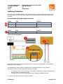
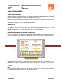
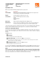
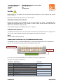
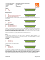
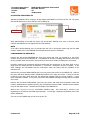
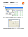
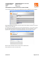
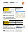
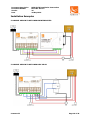
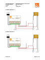
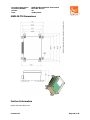
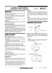
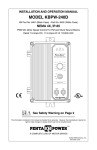
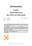
MERLIN
Transformer Rectifier Monitor
(MERLIN TR)
Version 26
Abriox Limited
Imperial House
Imperial Park
Newport
NP10 8UH
Technical Support +44 (0)2921 250094
www.abriox.com
Document Description
Document Number
Version
Date
MERLIN TR Installation Instructions
DOC-001-01-017
26
26 May 2010
Contents
Contents....................................................................................................................................... 2
Safety Information ........................................................................................................................ 4
Maximum Input Voltage for ON/OFF Potential Channel ................................................................ 4
Maximum Input Voltage for MERLIN TR Volts Channel ................................................................. 4
Maximum Input Voltage for MERLIN TR Shunt Channel ................................................................ 4
Danger of Electric Shock ............................................................................................................ 4
Channel Input Protection............................................................................................................ 4
Battery Replacement.................................................................................................................. 4
Lightning Protection ...................................................................................................................... 5
Recommended Lightning Surge Arrestors .................................................................................... 5
Installation Diagram................................................................................................................... 5
Before Going to Site ...................................................................................................................... 6
Install the Software ................................................................................................................... 6
Check the TR ............................................................................................................................. 6
Check and Designate the MERLIN TR Monitors ............................................................................ 6
Equipment Check ....................................................................................................................... 7
Setting-up Your Mobile phone .................................................................................................... 7
On Site ......................................................................................................................................... 8
Housing the MERLIN TR and PSU ............................................................................................... 8
Powering the MERLIN TR ........................................................................................................... 8
Connecting the MERLIN TR to the Transformer Rectifier .............................................................. 8
Activating the MERLIN TR ........................................................................................................ 10
Configuring the MERLIN TR ...................................................................................................... 10
Post Site Configuration ................................................................................................................ 11
Check the Shunt Values in the CPSM Software........................................................................... 11
Check the Shunt Values in the iCPSM Software .......................................................................... 12
Configuring the Alarm Values in the CPSM Software................................................................... 13
Configuring the Alarm Values in the iCPSM Software .................................................................. 14
Configuring Reports in the CPSM Software ................................................................................ 15
Configuring Reports in the iCPSM Software ............................................................................... 15
Installation Examples .................................................................................................................. 16
5 Channel MERLIN TR with MERLIN Interrupter ......................................................................... 16
5 Channel MERLIN TR with Mercury Relay ................................................................................. 16
4 Channel MERLIN TR .............................................................................................................. 17
3 Channel MERLIN TR .............................................................................................................. 17
Commercial
Page 2 of 18
Document Description
Document Number
Version
Date
MERLIN TR Installation Instructions
DOC-001-01-017
26
26 May 2010
MERLIN TR Dimensions ............................................................................................................... 18
Further Information .................................................................................................................... 18
Commercial
Page 3 of 18
Document Description
Document Number
Version
Date
MERLIN TR Installation Instructions
DOC-001-01-017
26
26 May 2010
Safety Information
Please ensure you are familiar with the Electrical Safety Regulations of your Company and observe
them at all times.
MAXIMUM INPUT VOLTAGE FOR ON/OFF POTENTIAL CHANNEL
The ON/OFF Potential channel of the MERLIN Transformer Rectifier Monitor (MERLIN TR) is intended
to measure +/-5V. It can handle a maximum input voltage of 70V(AC) and 70VDC without damage.
MAXIMUM INPUT VOLTAGE FOR MERLIN TR VOLTS CHANNEL
The TR Volts channel of the MERLIN TR has a maximum input voltage range of 150V(AC) and
150VDC.
The MERLIN TR has protection against high voltage transients built in, but there is a limit to the
amount of energy it can dissipate.
A high energy voltage clamp rated up to 150V(AC) or 200VDC maximum is recommended to ensure
the Transformer Rectifier (TR) is protected and the MERLIN TR internal protection is not overloaded.
This is especially important in areas prone to lightning strikes.
MAXIMUM INPUT VOLTAGE FOR MERLIN TR SHUNT CHANNEL
The TR Shunt channel of the MERLIN TR provides readings up to 100mV(AC) and 100mVDC. The
channel itself should not be exposed to voltages greater than ±4Vpeak. Voltages greater than this
will cause the channel input protection to activate which can only protect the unit for a limited period
of time.
DANGER OF ELECTRIC SHOCK
When using the MERLIN TR on Transformer Rectifiers with an output greater than 30VAC or 60VDC
care should be taken as there is a danger of electric shock.
CHANNEL INPUT PROTECTION
Channels 1 and 3 have CAT IV surge protection at their rated input voltage ranges. Channel 2 has
CAT III surge protection at its rated input voltage range.
BATTERY REPLACEMENT
The MERLIN TR battery pack is specific to the product; please contact Abriox to order replacements.
Commercial
Page 4 of 18
Document Description
Document Number
Version
Date
MERLIN TR Installation Instructions
DOC-001-01-017
26
26 May 2010
Lightning Protection
For areas at risk of lightning strikes/surges, Abriox strongly recommends surge arrestors are fitted.
No surge arrestor can deal with a direct strike but this arrangement should provide a high level of
protection.
RECOMMENDED LIGHTNING SURGE ARRESTORS
Model
Type
Position
ASZH240C201
240V Single Phase 3 Wire Service
AC Supply
LPC11895-2120
0-180VDC
Transformer Rectifier Output
For Transformer Rectifiers that will not accept the LPC11895-2120:
Model
Type
Position
Epcos B60K130
Screw Terminals, 0-130V
Transformer Rectifier Output
INSTALLATION DIAGRAM
Ensure that the AC used to power the MERLIN TR PSU and Transformer Rectifier is isolated before
installing the surge arrestors.
The ASZH240C201 surge arrestor is installed across the MERLIN TR PSU AC input and the
Transformer Rectifier’s Positive Output/Ground Bed connection:
•
•
The white ground wire of the arrestor is connected to the Rectifier’s Positive Output/Ground
Bed connection (not electrical ground).
The black AC line wires are connected to the AC supplying the MERLIN TR PSU.
It is vital to keep the connections as short as possible.
Commercial
Page 5 of 18
Document Description
Document Number
Version
Date
MERLIN TR Installation Instructions
DOC-001-01-017
26
26 May 2010
Before Going to Site
INSTALL THE SOFTWARE
Make sure the iCPSM or CPSM software and its GSM modem are installed and running (essential).
Refer to the CPSM Installation Instructions for details on how to do this.
Make sure you have written down the phone number of the iCSPM or SIM card in the GSM modem
used by each CPSM. You must use the international format (+44 for UK, +1 for USA, then the area
code without a leading zero) for all MERLIN communications.
CHECK THE TR
The MERLIN TR Power Supply Unit (PSU) should be powered from the AC supply to the TR. Make
sure beforehand that there is a suitable power point available so that you can plug or wire the
MERLIN TR in easily on site. The AC supply needs to be fused (with 3A fuse).
CHECK AND DESIGNATE THE MERLIN TR MONITORS
Check that MERLIN TR has a SIM card installed and the phone number of the SIM card is written or
printed on the label on the front of the MERLIN TR. If you have purchased the MERLIN TR with a
communications package from Abriox, then this will have been completed for you.
MERLIN TR SIM Number
Pipeline and Location Printed Labels
Write the Pipeline name (up to 30 characters) and the Location name (up to 50 characters) on the
MERLIN TR front label with a permanent marker pen or printed label. Remember – you will have to
text these details to the CPSM / iCPSM so, to avoid mistakes, do not make them longer than
necessary.
NOTE
Do not exceed the character limitation for Pipeline and Location. If you do so the system will shorten
the names and they will not install as you had intended, if at all.
Commercial
Page 6 of 18
Document Description
Document Number
Version
Date
MERLIN TR Installation Instructions
DOC-001-01-017
26
26 May 2010
EQUIPMENT CHECK
Make sure you have the following equipment prior to going on site.
Item
Current Shunt
Description
Make sure you have the appropriate** current shunt for the output of the
TR. 20A 200mV or 50A 50mV is recommended.
Magnet
A strong magnet to activate the unit on site.
Consumables
Wires of suitable lengths and colours (1.5mm)
Crimps
Ring terminations
Tool Kit
Multi-meter
DVM to check the voltage and current readings on site.
Mobile Phone
Used for setting up the MERLIN TR monitors. See below for messages you
can store in your phone before going to site to make installation easier.
**The shunt needs to be able to handle the full output of the TR (and lightning strikes) whilst also
bearing in mind the MERLIN TR has an input range of 0 to +/-100mV on its TR Shunt channel.
SETTING-UP YOUR MOBILE PHONE
If you store the text messages required for installation beforehand it will be easier and save time in
the field. Write the messages on your mobile phone and save them as a Draft, Template or Outgoing
Message.
Commands to save:
CMD:READ
Tells the MERLIN TR to take an immediate reading.
CMD:CONFIG HQ1:+441234567891 HQ2:+441234567892
Tells the MERLIN TR the headquarters (HQs) to report in to (where the numbers in light grey are the respective
telephone numbers of your CPSM / iCPSM HQs).
CMD:INSTALL PIPE:PIPELINE NAME LOC:TR NAME
Sets the MERLIN TR Pipeline name and Location.
You can use the CMD:READ and CMD:CONFIG commands for all the MERLIN TR monitors you are
going to install. You will need a separate CMD:INSTALL for each MERLIN TR to give it its own name.
NOTE
You will need to set the phone’s SMS message validity to 1 hour to prevent an SMS message getting
stuck. For example, if an install message gets stuck in the network and arrives 3 days late, the units’
clock will be set 3 days slow. Setting the message validity to 1 hour stops this happening. Please
refer to your mobile phone’s user manual for information about this setting.
Commercial
Page 7 of 18
Document Description
Document Number
Version
Date
MERLIN TR Installation Instructions
DOC-001-01-017
26
26 May 2010
On Site
Please ensure you are familiar with the Electrical Safety Regulations of your Company and observe
them at all times.
Open the TR and ensure that power to the TR is isolated.
HOUSING THE MERLIN TR AND PSU
Prepare the mounting for the MERLIN TR and its Power Supply Unit (PSU). The MERLIN TR is
supplied with fixings that allow it to be screwed to a panel or wall. The PSU has four holes that also
allow it to be screwed to a panel or wall.
A dimensioned drawing of the MERLIN TR unit is on page 16.
POWERING THE MERLIN TR
The MERLIN TR monitor comes with its own PSU and should be powered from the AC supply to the
TR. You may need to identify the positive and negative wires using a multi-meter.
NOTE
The PSU needs to be fused (at 3A).
CONNECTING THE MERLIN TR TO THE TRANSFORMER RECTIFIER
The MERLIN TR has 12 connections (labelled A to L) and are briefly described on the front label of
the unit. The connections correspond with the labelled terminal block.
MERLIN TR Front Label
Terminal Block
For wiring we recommend rigid solid core or flexible 0.2 to 2.5mm2 (AWG 24-12).
Wire up the terminal block as follows:Terminal
A
B
C
D
E
F
G
H
I
J
K
L
Commercial
Description
0V – PSU Connection
+12V – PSU Connection
0V
FS (Fail Safe) Electromechanical Relay Drive
INT (Interrupt) Solid State Relay Drive
Not Used – Leave Unconnected
ON/OFF Potential –ve
ON/OFF Potential +ve
TR Volts –ve
TR Volts +ve
TR Shunt –ve
TR Shunt +ve
Function
MERLIN TR PSU
Relay Control
N/A
ON/OFF Potential
TR Volts
TR Amps
Page 8 of 18
Document Description
Document Number
Version
Date
MERLIN TR Installation Instructions
DOC-001-01-017
26
26 May 2010
Power
A
B
0V
+12V
Relay Control
C
D
E
0V
FS Electromechanical Relay Drive
INT Solid State Relay Drive
If a MERLIN Interrupter or Mercury Relay are not being installed these connections should all be left
unconnected.
Not Used
F
Not Used
ON/OFF Potential
G
H
ON/OFF Potential –ve
ON/OFF Potential +ve
Connect –ve to the reference cell, connect +ve to the pipe, ideally via a test wire connected directly
to the pipe (this will allow IR free ON potential reads). If this is not available then connect to the
pipe side of the MERLIN Interrupter or Mercury Relay. The connection must be made on the pipe
side of the relay to allow OFF potential reads to be taken.
If there is no reference cell, or pipe potentials are not required, link G to H.
NOTE
The pipe will be connected to the –ve output of the TR. MERLIN TR’s ON/OFF Potential +ve is
connected to the pipe (and therefore the -ve output of the TR). This means MERLIN TR will read
conventionally i.e. a negative ON potential.
TR Volts
I
J
TR Volts -ve
TR Volts +ve
Connect across the TR output terminals.
TR Shunt
K
L
TR Amps -ve
TR Amps +ve
The shunt can be installed on either output of the TR. The correct shunt needs to be selected to
handle the maximum output of the TR, and lightning surges, whilst giving the best resolution to the
current reading. The TR Shunt channel can read 0 to 100mV. If the TR has a current shunt that can
be accessed then this can be used. If there is no current shunt then link K to L. With all connections
made, plug the terminal block into the unit and apply power to the TR and the MERLIN TR’s PSU.
Commercial
Page 9 of 18
Document Description
Document Number
Version
Date
MERLIN TR Installation Instructions
DOC-001-01-017
26
26 May 2010
ACTIVATING THE MERLIN TR
Activate the MERLIN TR by running a strong magnet past RESET on the front of the unit. The green
LED should flash twice to show that the unit is waking up.
Reset
Green LED
After approximately 60 seconds the green LED should start flashing once every 2 seconds, which
confirms the MERLIN TR has logged onto the GSM network.
NOTE
If the LED is double-flashing every 2 seconds then the unit is running but cannot log onto the GSM
network. Please refer to the MERLIN LED Descriptions document for full details.
CONFIGURING THE MERLIN TR
Retrieve the pre-stored CMD:READ text from your phone and send (or forward) it to the phone
number on the front of the MERLIN TR. The MERLIN TR will take a reading and send it back to your
phone, typically within 60 seconds (note that the current shunt reading is displayed in microvolts).
Check the levels are all consistent with those taken with the multi-meter. If the shunt input is overrange then the reading will clip at maximum i.e. 150.00mV. Change the shunt if necessary. If any
other readings are inconsistent with the multi-meter check the wiring and the condition of the
reference cell.
Retrieve the pre-stored CMD:CONFIG text from your phone and send it to the MERLIN TR. Wait for
the reply, and check that the CPSM / iCPSM HQ numbers in the reply are correct. If they are not the
numbers of your HQs, check that your pre-stored text message sent the correct numbers – it may
have contained a mistake. In any case, resend the CMD:CONFIG message ensuring that the numbers
are correct.
Retrieve the pre-stored CMD:INSTALL text from your phone and check that the Pipeline name and
Location descriptions are spelled correctly (this is important because CPSM / iCPSM uses the Pipeline
name as the folder name). Send this text message to the MERLIN TR.
Wait for the “Pipeline/Location successfully installed” reply - this could take a minute or two
depending on the network and GSM signal strength. You will get a separate confirmation from each
CPSM / iCPSM HQ.
The unit is now installed and you can close up the TR.
Commercial
Page 10 of 18
Document Description
Document Number
Version
Date
MERLIN TR Installation Instructions
DOC-001-01-017
26
26 May 2010
Post Site Configuration
CHECK THE SHUNT VALUES IN THE CPSM SOFTWARE
To check/configure the shunt value on the MERLIN TR, from the main CPSM window select the
MERLIN TR unit to configure.
Right-click the unit and select Properties, from the new window, select the Scaling tab.
Enter the shunt values in the voltage and current fields. You can select millivolts/Volts and
milliamps/Amps from the drop-down menus. When the shunt information has been entered, click the
Update Now button. An acknowledgement message will be received. You can now close this window.
Commercial
Page 11 of 18
Document Description
Document Number
Version
Date
MERLIN TR Installation Instructions
DOC-001-01-017
26
26 May 2010
CHECK THE SHUNT VALUES IN THE ICPSM SOFTWARE
To check/configure the shunt value on the MERLIN TR, from the main iCPSM window select the
MERLIN TR unit to configure.
On the right-hand side of the window, scroll down and click the Configure Location link. In the new
window, select the Scaling tab.
Enter the shunt vales in the voltage and current fields. You can select millivolts/Volts and
milliamps/Amps from the drop-down menus. When the shunt information has been entered, click the
Update button.
Click the Back link to return to the main screen.
Commercial
Page 12 of 18
Document Description
Document Number
Version
Date
MERLIN TR Installation Instructions
DOC-001-01-017
26
26 May 2010
CONFIGURING THE ALARM VALUES IN THE CPSM SOFTWARE
To set the alarm thresholds, right-click the unit and select Properties, in the new window, select the
Alarms tab.
Low and High alarm thresholds can be set on all the monitored channels. The Low alarm is always
the more negative threshold and the High alarm is always the more positive threshold. This is
important when setting alarms for the ON and OFF potentials, which are negative numbers.
Enable the alarms by checking the “Alarms Enabled” check box and click “Update Now”. A message
box will state that the alarm thresholds will be sent to the unit. Only when the unit acknowledges
these will the database be updated. Click the Close button to return to the main screen.
Commercial
Page 13 of 18
Document Description
Document Number
Version
Date
MERLIN TR Installation Instructions
DOC-001-01-017
26
26 May 2010
CONFIGURING THE ALARM VALUES IN THE ICPSM SOFTWARE
To set the alarm thresholds, from the main iCPSM window select the MERLIN TR unit to configure.
On the right-hand side of the window, scroll down and click the Configure Location link. In the new
window, select the Alarms tab.
Low and High alarm thresholds can be set on all the monitored channels. The Low alarm is always
the more negative threshold and the High alarm is always the more positive threshold. This is
important when setting alarms for the ON and OFF potentials, which are negative numbers.
When the alarm information has been entered, click the Update button.
Click the Back link to return to the main screen.
Commercial
Page 14 of 18
Document Description
Document Number
Version
Date
MERLIN TR Installation Instructions
DOC-001-01-017
26
26 May 2010
CONFIGURING REPORTS IN THE CPSM SOFTWARE
The MERLIN TR will report as follows:
Report
Data
For the first 7 days
Daily at the programmed time.
The min, max and average for each of
the monitored parameters for the day
(MERLIN checks the TR hourly)
After the first 7 days
Weekly on the programmed day and
time (default is Monday at 2am).
The min, max and average for each of
the monitored parameters for the
previous week (MERLIN still checks the
TR hourly)
To configure the reports select the MERLIN TR unit,
right-click and select Properties. Click on the Reporting
tab and set the options as you require.
Click the Update button to save changes, once saved click
the Close button to return to the main screen.
NOTE
During installation CPSM will automatically allocate a
reporting time to each unit. Report times are staggered
by two minute intervals to allow the system to operate
efficiently. These times can be changed if required.
CONFIGURING REPORTS IN THE ICPSM SOFTWARE
The MERLIN TR will report as follows:
Report
Data
For the first 7 days
Daily at the programmed time.
The min, max and average for each of
the monitored parameters for the day
(MERLIN checks the TR hourly)
After the first 7 days
Weekly on the programmed day and
time (default is Monday at 2am).
The min, max and average for each of
the monitored parameters for the
previous week (MERLIN still checks the
TR hourly)
To configure reporting, from the main iCPSM window
select the MERLIN TR unit to configure. On the righthand side of the window, scroll down and click the
Configure Location link.
In the new window, select the Reporting tab and set the
options as you require. Click the Update button to save
changes, once saved click the Back link to return to the
main screen.
NOTE
During installation iCPSM will automatically allocate a
reporting time to each unit. Report times are staggered
by two minute intervals to allow the system to operate efficiently. These times can be changed if
required.
Commercial
Page 15 of 18
Document Description
Document Number
Version
Date
MERLIN TR Installation Instructions
DOC-001-01-017
26
26 May 2010
Installation Examples
5 CHANNEL MERLIN TR WITH MERLIN INTERRUPTER
5 CHANNEL MERLIN TR WITH MERCURY RELAY
Commercial
Page 16 of 18
Document Description
Document Number
Version
Date
MERLIN TR Installation Instructions
DOC-001-01-017
26
26 May 2010
4 CHANNEL MERLIN TR
3 CHANNEL MERLIN TR
Commercial
Page 17 of 18
Document Description
Document Number
Version
Date
MERLIN TR Installation Instructions
DOC-001-01-017
26
26 May 2010
MERLIN TR Dimensions
Further Information
Please visit www.abriox.com
Commercial
Page 18 of 18