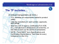
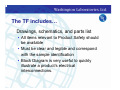
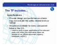
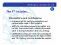
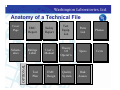
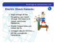
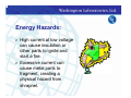
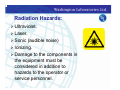
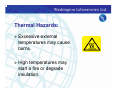
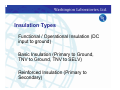
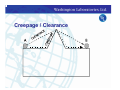
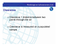
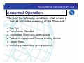
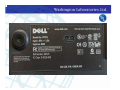
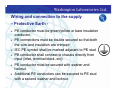
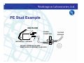
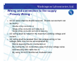
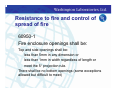
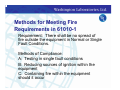
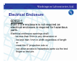
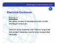
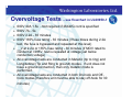
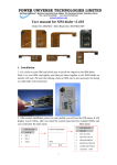
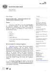
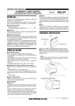
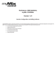
1
Designing for Success
Product Safety
Compliance
Berri Remenick
NARTE Certified Product Safety Engineer
Product Safety Manager
Washington Laboratories, Ltd.
Laboratory Workshop
June 18, 2004
Frederick, MD
Washington Laboratories (301) 417-0220 web: www.wll.com
7560 Lindbergh Dr. Gaithersburg, MD 20879
Overview
¾ North
American Requirements
¾ European Requirements
¾ Product Safety Hazards
¾ Product Safety Design Guidelines for
60950-1 and 61010-1
North American Safety
Requirements
•
Product Liability
•
•
Customer demands
•
•
Threat of Product Liability Lawsuits
Contractual Requirements
Legal requirements
•
•
•
•
•
Occupational Safety and Health Agency
(OSHA) (CFR 1910.399) for workplace safety
National Electric Code: NEC requires listing of
products connected to telephone lines
Local Laws. Enforced by local authorities
Canadian Provincial Laws
Mexican Product Safety Requirements
North American Safety
Requirements
Routes to Conformance
•
•
•
•
USA
- Underwriters Laboratories, Inc. (UL)
- NRTL: Nationally Recognized Testing Laboratories
accredited by OHSA (TUV, NTS, etc)
Canada
• CSA
• c-UL
• c-NRTL (cTUV)
Mexico
- NOM
UL Standards (a short list)
UL 60950-1*: Information Technology Equipment
(formerly UL1950)
UL 6500*:
Audio-Video Products and Accessories
(formerly UL1492 and UL1409)
UL 60601-1: Medical Electrical Equipment
(former UL 2601-1)
UL 508:
Industrial Control Equipment
UL61010A-1: Lab equipment
(formerly UL3101-1)
* WLL is in the UL CAP Engineering Program for these
standards
European Safety Requirements
¾
¾
¾
¾
¾
¾
New Approach Directives
• Self-Certification
• Technical Construction File
Evidence of conformity to essential requirements
• EMC and Safety
Intended for Market Inspectors
Documentation to support the use of the CE Marking
is required.
Manufacturer Affixes CE Mark
Notified Body Required for some products
European Safety Requirements
Routes to Conformance
¾ Self
declare by using CE Mark
¾ Use CE Mark with a competent body
review
¾ Obtain TUV, VDE, or other European
safety approval mark in addition to CE
Mark
•
Member States
•
•
•
•
•
•
•
•
Austria
Luxembourg
The Netherlands
Portugal
Spain
Sweden
United Kingdom
Ireland
Italy
Belgium
Denmark
Finland
France
Germany
Greece
New members coming…..
•
•
•
•
•
•
•
Norway
Iceland
Lichenstein
Czech Republic
Cyprus
Estonia
Latvia
Hungary
Lithuania
Malta
Poland
Slovakia
Slovenia
Low Voltage Directive
¾
¾
¾
¾
¾
Has been around since 1973 - recently amended
(1993) to include the use of the CE Marking.
For products intended for connection to Mains
voltages between 50 and 1000V~.
Generally for household products, office or laboratory
equipment - NOT for machinery or medical products.
For products where hazards are primarily electrical in
nature.
Documented internal QUALITY ASSURANCE
required.
Low Voltage Directive
Common Standards
¾Information Technology
Equipment EN60950
¾Laboratory Equipment EN61010
¾Audio Video Equipment EN60065
¾Household Appliances EN60335
Other Common Directives
¾
¾
¾
¾
RTTE Directive: For products connecting to the
telephone network or containing radio transmitters.
Requirements for the Low Voltage Directive apply
without minimum voltage limitations.
General Product Safety Directive: “Catch all”
directive stating that all products must be safe.
Machinery Directive: For devices with hazards
primarily mechanical in nature.
Medical Devices Directive: For Medical Devices.
NEW APPROACH DIRECTIVES
•
•
•
•
•
•
•
•
•
•
•
•
•
•
•
•
•
•
•
•
•
- Low Voltage (73/23/EEC) Amended by 93/68/EEC
-Simple Pressure Vessels (87/404/EEC) Amended by 90/488/EEC
-Toy Safety (88/378/EEC) Amended by 93/68/EEC
-Construction Products (89/106/EEC) Amended by 93/68/EEC
-EMC (89/336/EEC) Amended by 93/68/EEC
-Machinery (98/37/EEC)
-Personal Protective Equipment (89/686/EEC)
-Non-Automatic Weighing Instruments (90/384/EEC) Amended by 93/68/EEC
-Appliances burning gaseous fuels (90/396/EEC) Amended by 93/68/EEC
-Radio Equip & Telecom Terminal Equipment (91/263/EEC)
-Hot Water Boilers (92/42/EEC) Amended by 93/68/EEC
-Medical Devices (93/42/EEC)
-Recreational Craft (94/25/EEC)
-Active-implantable medical devices (90/385/EEC) Amended by 93/42/EEC
-Explosives for civil uses (93/15/EEC)
-Equipment explosive Atmospheres – ATEX (94/9/EC)
-Packaging and Packaging Waste (94/62/EEC)
-Lifts (95/16/EC)
-Pressure Equipment (97/23/EC)
-In-vitro diagnostic medical devices (98/79/EC)
-Cableway installations designed to carry persons (2000/9/EC)
Other Directives based on New
Approach
•
•
•
•
•
•
•
-Interoperability of trans-European high speed rail
system (96/48/EC)
-Energy Efficiency requirements (96/57/EC)
-Marine Equipment (96/98/EC) Amended by
98/85/EC
-Interoperability of trans-European conventional rail
system (2001/16/EC)
-Transportable pressure equipment (1999/36/EC)
-Noise emission in the environment by equipment for
use outdoors(2000/14/EC)
-Energy efficiency requirements for ballasts for
fluorescent lighting (2000/55/EC)
What is a TF ?
¾
A Technical File (TF) brings together all
required elements to show compliance with
applied standards and incorporates the items
outlined in the directive.
¾ The TF is a neat, organized, professionally
prepared report which will be accepted by any
authority in Europe
¾ The TF should make the product as
understandable as possible to a third-party not
familiar with the product
The TF includes…
•
A Test Report
• A clause-by-clause description of how the
product complies with the requirements
• Or why a particular requirement does not
apply.
The TF includes…
•
A Critical Component List (CCL)
• CCL identifies all components related to product
safety
• Lists the manufacturer, part number, approvals,
and ratings
• Must be a link to agency certificates(TUV,VDE,
UL), manufacturer’s declarations of conformity, or
test data to back up the claims of compliance.
• NOTE: There MUST be a Specifications and
Certification/Declaration or Test Data for every
component in the CCL.
The TF includes…
•
Drawings, schematics, and parts list
• All items relevant to Product Safety should
be available
• Must be clear and legible and correspond
with the sample identification
• Block Diagram is very useful to quickly
illustrate a product’s electrical
interconnections.
The TF includes…
•
Specifications
• Provide design and performance criteriamay not indicate the safety related limits or
ratings
• Should be available for every component
listed in the CCL
• Used to verify proper application of the relevant
parts only when the information does not
appear on an official document (agency
certificate, mDOC).
Spec
Sheet
Example
The TF includes…
•
Declarations and Certifications
• Are required for verifying compliance of
components used in the systems
• mDOCs should be properly formatted and
contain the correct part number (traceable
back to the specification and CCL listing)
• Certifications should have the correct part
number (traceable back to the specification
and CCL listing) and the standards applied
Certificate
Example
The TF also includes…
¾ Installation/User/Service
Instructions
¾ Photographs
¾ Copy
of the Declaration of Conformity
Declaration of Conformity
Application of Council Directive (s):
89/336/EEC, 72/23/EEC
Standard(s) to which Conformity is Declared:
EN55022, EN60950
Manufacture’s Name:
Manufacture’s Address:
COMPANY NAME
ADDRESS
Importer’s Name:
Importer’s Address:
(EU Representative’s Name)
(EU Representative’s Address)
Type of Equipment:
EQUIPMENT DESCRIPTION
Model Number:
MODEL NUMBER
Year of Manufacturer:
(Year of Manufacture)
I, the undersigned, hereby declare that the equipment specified above conforms to the above Directive(s)
and Standard(s).
__________________________
(Full Name, Title)
__________________________
(Signature)
_
_________________________
(Date)
Anatomy of a Technical File
Cover
Page
OPTIONAL
Schematics
EMC
EMC
Report
Report
Safety
Safety
Report
Report
Test
Equip.
List
Parts
List
Photos
Photos
Ratings
Label
User’s
User’s
Manual
Manual
Theory
Of
Operat’n
Specs
Specs
Certs
Certs
Test
Plan
EMC
Design
Quality
System
Risk
Assess.
Product Safety Hazards addressed
in 60950-1 and 61010-1
¾ Electric
Shock
¾ Energy
¾ Fire
¾ Mechanical
¾ Radiation
¾ Thermal
Electric Shock Hazards:
¾
¾
¾
High voltage at low
frequency can travel
through the heart and
cause ventricular
fibrillation.
Higher frequencies can
cause burns.
Voltages above 30Vrms or
60Vdc considered
hazardous.
Energy Hazards:
¾
¾
High current at low voltage
can cause insulation or
other parts to ignite and
start a fire.
Excessive current can
cause metal parts to
fragment, creating a
physical hazard from
shrapnel.
Fire Hazards:
¾ Excessive
temperatures can
ignite materials inside the
equipment or in close
proximity to external
surfaces.
¾ Beside the danger of the fire
itself, the release of toxic
gases is a concern.
Mechanical Hazards:
¾ Moving
parts.
¾ Expelled parts.
¾ Motor overspeed.
¾ Locked rotors or motor shafts.
¾ Sharp edges.
Radiation Hazards:
¾ Ultraviolet.
¾ Laser.
¾ Sonic
(audible noise)
¾ Ionizing.
¾ Damage to the components in
the equipment must be
considered in addition to
hazards to the operator or
service personnel.
Thermal Hazards:
¾ Excessive
external
temperatures may cause
burns.
¾ High
temperatures may
start a fire or degrade
insulation.
Product
Product Safety
Safety Design
Design
Guidelines
Guidelines for
for 60950-1
60950-1 and
and
61010-1
61010-1
¾
¾
¾
¾
¾
¾
¾
Design and Construction Requirements
Labeling and Markings
Instructions Manuals
Language
Wiring and Connection to the supply
Resistance to Fire and control of spread of
fire
Connection to Telecommunications Network
Design
Design Requirements
Requirements
Protection against electric shock and
energy hazards:
•
The OPERATOR can not touch bare or inadequately
insulated parts at hazardous voltage or energy levels.
•
Hazardous Voltage Level is typically >30Vrms,
42.4Vpeak, or 60VDC.
Hazardous energy is typically >240VA or 8A
Protection may provided via insulation, guarding or
interlocking.
What is Insulation?
•
Physical barrier between two parts
(tape, plastic shield, wire insulation,
enclosure, etc)
•
Separation between two parts
(creepage or clearance distance)
Insulation Types
•
Functional / Operational Insulation (DC
input to ground)
•
Basic Insulation (Primary to Ground,
TNV to Ground, TNV to SELV)
•
Reinforced Insulation (Primary to
Secondary)
Reinforced Insulation Example
Spacings
¾ Determine
insulation required for your
circuit.
¾ Determine maximum working voltage
for your circuit.
¾ Go to tables in standard and determine
required creepage and clearance
distances.
¾ Maintain these distances in your design.
Creepage / Clearance
Creepage
¾ Creepage
= distance between two
points along the surface
¾ Creepage
is measured on 1:1 artwork
or on a blank board
¾ Locations
of circuits determined by
reviewing schematics
Clearance
¾ Clearance
= distance between two
points through the air
¾ Clearance
sample
is measured on a populated
Abnormal
Abnormal Operation
Operation
“None of the following conditions shall create a
hazard within the meaning of the Standard:”
¾
¾
¾
¾
¾
¾
Fan Fail
Transformer Overload
Component Short- and Open-circuits
Failure of unapproved Thermal Limiting device.
Locked Rotor.
and others, depending upon equipment.
Labeling
Labeling and
and Marking
Marking
¾
¾
¾
¾
¾
¾
Rated voltage, current or power, frequency
Manufacturer’s name or registered
trademark.
Model or type number.
Fuse replacement info (if applicable).
IEC symbols wherever possible.
Warnings and Cautions appropriate for the
particular equipment.
User
User Instructions
Instructions
¾
¾
¾
¾
¾
¾
Installation Instructions - information
regarding mounting, connection to the supply,
ventilation, input ratings, etc.
All information regarding use, cleaning,
maintenance (if necessary).
All safety warnings and cautions.
Restricted Access Location statement if
applicable.
Rack Mount instructions.
Instructions for Racks.
Language
Language
¾
‘Safety-related’ information to be in
appropriate language.
¾
Service Instructions may be in English.
¾
Many times, the entire User Manual must be
translated (for specific market areas,
dependent on intended end-user, etc).
Wiring and connection to the supply
– Protective Earth ¾
¾
¾
¾
¾
¾
PE conductor must be green/yellow or bare insulation
conductor
PE connections must be double secured so that both
the wire and insulation are crimped
IEC PE symbol shall be marked adjacent to PE stud
PE conductor shall connect to chassis directly from
input (inlet, terminal block, etc).
PE conductor must be secured with washer and
locknut.
Additional PE conductors can be secured to PE stud
with a second washer and locknut.
PE Stud Example
EMI FILTER
CHASSIS
CONNECTION
MECHANICALLY SECURED
GROUND: GREEN/YELLOW WIRE
SAME GAUGE AS OR BIGGER THAN SUPPLY
TO OTHER
GROUNDS
Wiring and connection to the supply
– Primary Wiring ¾
•
•
•
¾
All AC wires shall be double secured. Double securement can
be met by:
Double crimp connector or
Single crimp connector and cable tie or
Single crimp connector and shrink sleeving.
AC wiring shall be rated for the maximum working voltage and
current.
¾ AC wiring shall be isolated from low voltage wiring or low
voltage parts, this can be accomplished by:
•
Shrink sleeving the AC conductors or
•
By routing the AC conductors away from low voltage wires
•
and securing with cable ties or
•
By using UL1015 Reinforced Insulation wire.
Resistance to fire and control
of fire spreading
Flammability of enclosure, internal,
and external parts
• Flammability ratings
•
•
•
•
•
•
•
•
5VA
5VB
V0
V1
V2
HB40
HB75
Resistance to fire and control of
spread of fire
60950-1
• Fire enclosure openings shall be:
•
•
•
•
•
•
Top and side openings shall be:
less than 5mm in any dimension or
less than 1mm in width regardless of length or
meet the 5° projection rule.
There shall be no bottom openings (some exceptions
allowed but difficult to meet)
Methods for Meeting Fire
Requirements in 61010-1
•
Requirement: There shall be no spread of
fire outside the equipment in Normal or Single
Fault Conditions.
•
Methods of Compliance:
A: Testing in single fault conditions
B: Reducing sources of ignition within the
equipment
C: Containing fire within the equipment
should it occur
•
•
•
Electrical Enclosure
•
60950-1
•
Even if fire enclosure is not required an
electrical enclosure is required for hazardous
parts.
•
Electrical enclosure openings shall:
- be less than 5mm in any dimension or
- be less than 1mm in width regardless of length
or
- meet the 5° projection rule or
- not allow access to hazardous parts via the test
finger or test pin.
•
•
•
•
•
•
Electrical Enclosure
•
61010-1
•
Not allow access to hazardous parts via the
test finger or test pin.
•
Test pin 4mm diameter and 100mm long shall
not contact hazardous parts when suspended
vertically.
Connection to
Telecommunications
Networks (60950-1)
¾
¾
¾
TNV-1: Within SELV limits, but subject to
overvoltages (goes outside the building). T1,
T3, DS1, DS3, etc.
TNV-2: Exceeds SELV voltages, but not
subject to overvoltages (does not leave the
building). Unit which generates a ringing
signal to connect to a local phone.
TNV-3: Exceeds SELV limits and is subject
to overvoltages (goes outside the building).
Port that connects to the PSTN.
Overvoltage Tests – see flowchart in UL60950-1
¾
¾
¾
¾
¾
¾
¾
600V 40A 1.5s - Not required if 26AWG cord is specified
600V 7A - 5s
600V 2.2A - 30 minutes
600V 135% fuse rating - 30 minutes (if fuse blows during 2.2A
test, the fuse is bypassed and repeated at this level)
__V at 2.2A or 135% fuse rating - 30 minutes (if MOV rated to
conduct at >285V, test is repeated at voltage just below
conduction voltage)
All overvoltage tests are conducted in Metallic (tip to ring) and
Longitudinal (Tip and Ring to ground) modes. If unit does not
have a ground connection, then only metallic mode is
performed.
All overvoltage tests are conducted in both On-hook and Offhook modes (therefore unit must be able to stay off-hook for 30
minutes)
Overvoltage Test Example
Overvoltage Test Example
Common Non-compliances
Discovered During Safety
Evaluations
¾
¾
¾
¾
Not using European approved
components (requires additional testing)
CE marked components meet EMC
requirements only, not safety (requires
additional testing).
Inadequate Labeling (Warning labels
don’t use IEC symbols, no voltage
ratings, no Protective Earth labels, etc.)
Overcurrent protection not provided
(Fuses, circuit breakers, etc.)
Common Non-Compliances Continued
¾
¾
¾
¾
Improper Primary Wire Connection Methods
Improper Protective Earth Connection
Methods
Not providing adequate documentation
(schematics, wiring diagrams, manuals, parts
lists, etc.)
Not considering Creepage / Clearance
requirements (Requires re-designing circuit
boards)
Washington
Washington Laboratories,
Laboratories, Ltd.
Ltd.
¾
¾
¾
¾
¾
¾
Help you select the proper Directives and
Standards to apply to your product.
Evaluate your product to the appropriate
Safety Standard and offer solutions for noncompliances.
Provide product design assistance.
Assist in obtaining UL or NRTL, c-UL or cNRTL, GS Mark, and other approvals.
WLL is approved under the UL CAP Program
for UL60950 and UL6500.
WLL is a Partner Test Lab for TUV Rheinland
of North America for 60950, 61010, and
60065
Washington Laboratories, Ltd.
•
Give us a call or send us info about your product we’re here to help!
•
Berri Remenick
Product Safety Manager
Phone:
301-473-1255
Fax:
301-473-1257
E-mail:
[email protected]
•
•
•
•