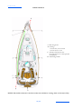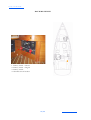
1
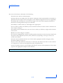
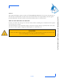
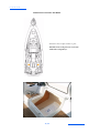
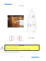
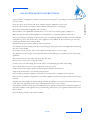
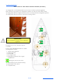
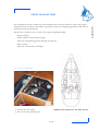
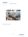
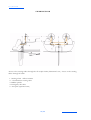
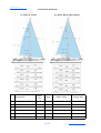
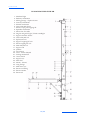
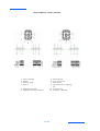
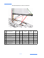
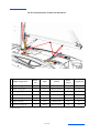
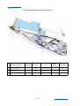
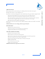
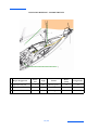
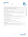
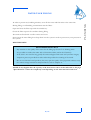
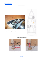
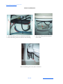
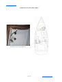
SUN ODYSSEY 42 DS
CROISIERE
OWNER'S MANUAL
5.1.2 ISO 10 240
CONTENTS
SUN ODYSSEY 42 DS Anglais
Update 08/2005
Index 0
Code: 986735
Total number of pages: 132
INTRODUCTION
HISTORY OF UPDATES
Chapter 1............................................................................................................................. Page 5
SPECIFICATIONS AND WARRANTY
Chapter 2 .......................................................................................................................... Page 13
SAFETY
Chapter 3 .......................................................................................................................... Page 27
HULL
Chapter 4 .......................................................................................................................... Page 37
DECK
Chapter 5 .......................................................................................................................... Page 49
RIGGING AND SAILS
Chapter 6 .......................................................................................................................... Page 71
ACCOMMODATIONS
Chapter 7 .......................................................................................................................... Page 81
PLUMBING
Drawings at the end of the manual
Chapter 8 .......................................................................................................................... Page 93
ELECTRIC SYSTEMS
Drawings at the end of the manual
Chapter 9 .........................................................................................................................Page 103
DIESEL ENGINE
Chapter 10........................................................................................................................ Page 119
LAUNCHING
Chapter 11 ........................................................................................................................Page 125
WINTER STORAGE
PERSONAL NOTES
At the end of the manual
APPENDIX AND OPTIONAL EXTRAS
At the end of the manual
5.1.3, 5.2 ISO 10 240
HISTORY OF UPDATES
• Index 0...................................................................................................................................... 08/2005
5.1.3, 5.2 ISO 10 240
INTRODUCTION
We share a common passion for the sea: we, JEANNEAU as shipbuilders and you who want to live
your passion on the Seven Seas.
We are delighted to welcome you to the great family of JEANNEAU boat owners and we congratulate
you on it.
This manual was meant to help you to enjoy your boat comfortably and safely. It includes the boat
specifications, the equipment provided or installed, the systems and tips on her operation and
maintenance.
Read this manual carefully before you put out to sea so that you can make the most of her and avoid
any damage and any trouble. Get to know your boat before you sail.
We keep improving our boats as we want you to benefit from the technological developments, new
equipment or materials and our own experience. That is the reason why the specifications and
information given are not contractual, they may be modified without prior notice or up dates.
This owner's manual is designed in accordance with the ISO 10 240 standard requirements, it has a
general purpose and it may sometimes list some equipment or accessories or deal with some points or
questions that are not relevant to your own boat. In case of doubt refer to the inventory list you were
given when you bought your boat.
Our network of JEANNEAU authorized dealers will be at your disposal to help you get acquainted with
your boat and will be the most qualified to take care of her maintenance.
If this is your first boat or if you change to a new type of boat which you are not used to, get some
training in boat control and sailing to ensure your safety and comfort. Your dealer, your international
sailing association or your yacht club will be very happy to recommend local sailing schools or
professional instructors.
Even if everything has been provided for and designed for the safety of the boat and the safety of her
users, don't forget that sailing highly depends on the weather conditions, the sea condition, and that
only an experienced and very fit crew, handling a well-maintained boat can sail satisfactorily.
1/132
5.1.3, 5.2 ISO 10 240
The sea and wind conditions that correspond to the design categories A, B or C are changeable and are
dependent on the hazards of unusually strong waves or gusty winds. Therefore total safety cannot be
guaranteed, even if your boat meets the requirements of a category.
Always listen to the weather forecast before you put out to sea.
Make sure the sea and wind conditions will correspond to the category of your boat and you and your
crew are able to handle the boat in these conditions.
The sea and the water are not the natural environment of Man and one has to respect their laws and
strength.
Adapt the use of your boat to her condition that wears out with time and use.
Any boat, however solid she may be, may be severely damaged if badly used. This is not compatible
with a secure navigation. Always adapt the speed and direction of your boat to the conditions of the sea.
The 'COLREG', an international regulation in order to prevent collision at sea, published by the
International Maritime Organization, specifies the steering and course regulations, the navigation lights
etc. throughout the world Make sure you know these regulations and you have on board a manual that
explains them.
In numerous countries, a licence, an authorization or a training course is requested. Make sure you have
this legal authorization before you use your boat.
Always use an experienced technician for the maintenance of your boat, the fitting of accessories and
the carrying out of small modifications. The written authorization of the builder or his legal
representative is compulsory for modifications that alter the specifications of the boat, in particular the
vertical layout of the grounds (putting up of a radar, modification of the mast, change of the engine etc.).
For the essential or optional equipment (engine, electronics etc.) refer to their respective manual
delivered with your boat.
2/132
5.1.3, 5.2 ISO 10 240
The users of the boat are informed of the following:
- The entire crew must be trained properly.
- The boat shall not be loaded more with than the maximum load recommended by the builder, in
particular the total weight of the food supplies, of the different equipment that are not supplied by
the builder and of the persons on board. The weight of the boat shall be properly distributed.
- The water in the bilge shall be kept at its minimum.
- The stability is reduced when you add weight in the upper parts.
- In case of heavy weather, the hatches, lockers and doors shall be closed in order to minimize the
risk of water coming in.
- The stability may be reduced when you tow a boat or when you lift heavy weights with the davits
or the boom.
- Breakers are serious dangers to stability.
- If your boat is equipped with a liferaft, carefully read the instructions. In the boat there shall be all
the proper safety equipment (harness, flares, liferaft etc.) depending on the type of boat, the
country, the weather
- The crew must be familiar with the use of all the safety equipment and the emergency safety
procedures (MOB, towing etc.).
- Anyone on the deck shall wear a life jacket or a buoyancy aid. Please note that in some countries
it is compulsory to wear an homologated buoyancy aid permanently.
- A part of the data is shown on the builder's plate fixed to the boat. The explanation of these data
is given in the appropriate chapters of this manual.
Keep this manual in a safe place and hand it over to the new owner if you sell your boat.
3/132
5.1.3, 5.2 ISO 10 240
1
SPECIFICATIONS AND WARRANTY
YOUR BOAT
TERMS AND CONDITIONS OF WARRANTY
5/132
5.1.3, 5.2 ISO 10 240
SPECIFICATIONS
L.O.A............................................................................................................................................. 12,93 m/42’ 5’’
Length of hull............................................................................................................................... 12,59 m/41’ 3’’
L.W.L............................................................................................................................................. 11,60 m/38’ 0’’
Max. beam ...................................................................................................................................... 4,13 m/13’ 6’’
Waterline beam ............................................................................................................................ 3,33 m/10’ 11’’
Ballast weight Deep keel.......................................................................................................2 553 kg/5 628 lbs
Draft Deep keel ............................................................................................................................. 2,13 m/6’ 11’’
Ballast weight Shallow keel .................................................................................................. 2 781 kg/6 131 lbs
Draft Shallow keel ........................................................................................................................... 1,60 m/5’ 2’’
Light displacement - Deep keel.........................................................................................8 925 kg/20 063 lbs
Light displacement - Shallow keel.....................................................................................9 122 kg/20 506 lbs
Maximum load displacement - deep keel.......................................................................11 152 kg/25 070 lbs
Maximum load displacement - shallow keel..................................................................11 349 kg/25 512 lbs
Maximum load recommended by the builder ................................................................... 2 382 kg/5 355 lbs
Including the mass of the persons who are authorized on board (75 kg/165 lbs per adult), the supplies,
the liquids that can be used (fresh water and fuel) in fixed completely full tanks, the additional loads, the
optional equipments, the liferaft and the scope for load.
Water tank capacity .................................................................................................................... 355 l/94 US gal
Fuel oil tank capacity.................................................................................................................. 130 l/34 US gal
Refrigeration unit capacity ........................................................................................................ 140 l/37 US gal
Recommended engine power (diesel engine).......................................................................... 53 CV (39 kW)
Battery capacity .......................................................................................................................................................
Cabins..................................................................................................................................................................... 2
Berths .................................................................................................................................................................5/7
CE CATEGORY
2 cabins
A
8 persons
B
10 persons
C
14 persons
Architect................................................................................................... Marc LOMBARD, Jeanneau Design
SAILS
Furling mainsail...................................................................38 m2/409 sq.ft
Furling genoa.......................................................................43 m2/463 sq.ft
Spinnaker ........................................................................125 m2/1 345 sq.ft
I ..............................................................................................15,76 m/51’ 8’’
J ..............................................................................................4,86 m/15’ 11’’
P ..........................................................................................15,24 m/49’ 11’’
E .................................................................................................... 4,90 m/16’
The sails are the main propulsion means of the SUN ODYSSEY 42 DS.
6/132
5.1.3, 5.2 ISO 10 240
Category A 'In the open sea'
This boat is designed for sailing in winds that may exceed force 8 on the Beaufort scale and in waves of
a significant height of 4 m and more, and the boat is to a large extent self-sufficient. Unusual conditions
such as hurricanes are excluded. You may meet with such conditions when you sail long crossings, for
instance across the oceans, or close to the shore, when you are not protected from the wind or waves
over several hundreds of nautical miles.
The significant height of a wave is the average height of the upper third of the waves, that approximately
corresponds to the height of a wave an experienced observer can assess. Some waves will be twice as
high as this value.
The conformity of the SUN ODYSSEY 42 DS model to the 94/25/CE directive is attested by Bureau
Veritas.
7/132
SPECIFICATIONS AND WARRANTY
1
5.1.3, 5.2 ISO 10 240
YOUR BOAT
Version
..............................................................................
NAME OF THE BOAT
..............................................................................
NAME OF THE OWNER
..............................................................................
ADDRESS
..............................................................................
..............................................................................
..............................................................................
HULL NUMBER
..............................................................................
SERIAL NUMBER
..............................................................................
REGISTRATION NUMBER
..............................................................................
DELIVERY DATE
..............................................................................
DOOR KEY NUMBER
..............................................................................
MAKE OF ENGINE
..............................................................................
ENGINE SERIAL NUMBER
..............................................................................
ENGINE KEY NUMBER
..............................................................................
Your agent
CHANTIERS JEANNEAU - BP 529 - 85505 LES HERBIERS cedex - FRANCE
Tel. (33) 02 51 64 20 20 - Fax (33) 02 51 67 37 65
Internet : http://www.jeanneau.com(fr).
8/132
5.7 ISO 10 240
TERMS AND CONDITIONS OF WARRANTY
1
At the time of delivery of the boat the parties sign the Certificate of Delivery supplied by CHANTIERS
JEANNEAU for this purpose and this is equivalent to an agreement of compliance by the
purchaser-user.
The acceptance of delivery of the boat by the purchaser-user without reserve is equivalent to the
acceptance of the apparent condition of the boat in pursuance of the provisions of Section 1642 of the
Civil Code.
The terms of warranty are engaged only upon:
- the return to the After Sales Department in CHANTIERS JEANNEAU of the duly filled in
tear-away section of the Certificate of Delivery and of the Warranty Registration Card,
- the carrying out of the controls and service set forth by CHANTIERS JEANNEAU, being made
clear that the possible expenses of handling, transportation, parking, escorting which have been
incurred in the execution of the above mentioned directives are born exclusively by the
purchaser-user.
Article 2
The warranty is valid for a duration of 12 months from the date of delivery of the boat to the first
purchaser-user and it is strictly limited as the manufacturer chooses, to the replacement or free repair
of any part that has been found defective by the technical specialists of the latter and no compensation
whatsoever shall be paid in this respect.
As for components and accessories which visibly bear the trademark of another supplier, the warranty
shall be limited to the warranty provided by said supplier.
Article 3
With the exception of any prototype boats, RIGIFLEX boats, boats used for business purposes, or
boats specifically designed and/or equipped for racing, which have as a contractual warranty only that
indicated in article 2 above, the structure of the hull, the deck and the hull to deck joint and the hull to
keel joint is warranted against all manufacturing defects identified by the technical specialists of
CHANTIERS JEANNEAU, for a period of 5 years for monohull boats and 3 years for motor boats
and multihull boats.
However, any incident that affects the structure and does not result from a manufacturing defect
covered under the conditions of warranty, that would have resulted or not in the repair of the deck or
hull, shall effectively cancel all terms and conditions of warranty and without prejudice immediately.
The warranty period starts from the date of the first commissioning of the boat and at the latest from
the last day of the model year in which the boat was built, i.e. August 31 of the said year.
This warranty is strictly limited to the free repair of the manufacturing defects either in our yard or by
a repair shop or shipyard we authorized and no compensation whatsoever shall be paid in this respect.
9/132
SPECIFICATIONS AND WARRANTY
Article 1
Article 4
The following items are excluded from the terms of warranty as stated in articles 1 and 2 above:
- The transport and carriage expenses for the boat and parts as well as expenses and/or possible
losses resulting from the inability to use the boat and/or accessories, shall be born by the
purchaser,
- The deterioration or damages hereinafter listed as well as their consequences:
• Normal wear and tear,
• Cracks, cracking or fading of the gel coat,
• Damages resulting from:
- changes and modifications or repairs, even partial, performed in workshops different from
those authorized by our company,
- the failure to follow the recommended maintenance procedures stated in the owner's manual
delivered with the boat, or failure to follow the professional procedure,
- improper use, in particular careless use, or rash use, misuse or abnormal use,
- the participation in competitive events,
- acts of negligence as regards to the necessity to take the necessary measures of conservation,
- an accident or catastrophe such as explosion, fire, flood, storm, lightning, transport, riot,
theft, collision,
- unsuitable storage or transport conditions.
Article 5
The bringing into play of the warranty shall extend the period of warranty for a period equal to the one
that is necessary to carry out the repair work under the warranty, on the condition that the
afore-mentioned repair work requires an immobilization of the boat for minimum 7 consecutive days.
Article 6
In order to enjoy the above-specified warranty, the purchaser-user shall present the duly filled in
Certificate of Delivery and Warranty document each time a claim is presented and in a written, precise
and justified document he shall notify his authorized dealer-seller the defect or fault within 15 days from
the day when the defect or fault is discovered otherwise he will not enjoy this warranty.
The authorized dealer-seller shall inform the builder about the purchaser-user's claim within a period of
8 days from its receipt otherwise he shall have to bear the consequences resulting from his delay.
10/132
1
The authorized dealers, agents or sellers of CHANTIERS JEANNEAU do not have the authority to
alter the above warranty but, on their own account and in their own responsibility, they may grant
possible additional warranties which can bind the builder under no circumstances.
PRECAUTION BEFORE ANY REPAIR
Contact your seller who will give you the best advice and the suitable parts or materials for the repairs
you can carry out yourself.
It would be better to have important repairs of the hull or engine done by a professional. Your seller
can carry out these repairs or appoint a skilled person to carry them out.
DANGER
Contact your seller to find out what is possible for you to repair and above all what you must not do !
You could endanger your safety and lose your warranty.
11/132
SPECIFICATIONS AND WARRANTY
Article 7
5.3, 5.5, 5.6 ISO 10 240
2
SAFETY
SAFETY EQUIPMENT
GAS SYSTEM SAFETY INSTRUCTIONS
FIGHT AGAINST FIRE
BILGE PUMP SYSTEM
EMERGENCY TILLER
13/132
5.3.3 d) ISO 10 240
POSITION OF THE LIFERAFT
Liferaft in the cockpit locker to port
NOTE: If over 10 persons on board:
2 liferafts compulsory.
14/132
SAFETY EQUIPMENT
2
LIFERAFT
RECOMMENDATION
When sailing, never padlock or lock the liferaft locker.
Before you sail to sea, carefully read the instructions indicated on the liferaft to launch it.
WARNING
- Before you sail, list the compulsory safety equipment.
- Don't exceed the number of persons indicated in the chapter 'Specifications'.
- When you don't take into account the number of persons, the total weight of the persons and
equipment shall never exceed the maximum load recommended by the manufacturer.
- Use the seats provided.
RECOMMENDATION
Close the deck hatches and fore portholes each time before each trip
(including the companionway hatch in heavy weather).
ADVICE: Don't store anything below the floorboards.
15/132
SAFETY
The liferaft should be placed in a cockpit locker.
5.3.3 d) ISO 10 240
GAS VALVE
1. Valve on appliance
2. Valve on cylinder
Open valve
Closed valve
WARNING
- Don't use a solution containing ammonia.
- Don't use a flame to detect leaks.
- Don't smoke, don't use a naked flame when you change the gas cylinder.
NOTE: See gas circuit at end of manual.
16/132
GAS SYSTEM SAFETY INSTRUCTIONS
2
Close the valves on the system and on the cylinder when the appliances are not used.
Close the valves before you change cylinders and immediately in case of emergency.
Never leave unattended an appliance that is working.
Don't install or store flammable materials above or over the stove (curtains, papers, napkins etc.).
Make sure that the valves of the appliances are closed before you open the cylinder or hose valve.
In case you smell gas or find that the burners have gone out (although appliance models cut off automatically
if the flames go out), turn off the valves of the appliances. Do ventilate the boat in order to get rid of any
residual gas. Find the cause of the problem.
Regularly test the gas system in order to detect any gas leak.
Check all the connections using water and soap or detergent, closing the valves of the appliances and opening
the valve on the cylinder.
If you detect a leak, close the valve of the cylinder and repair before you use it again.
The appliances use the oxygen of the cabin and release combustible gases. Ventilate your boat when using
appliances.
Don't obstruct the air vents and at least leave the door open.
Don't use the oven or stove as back up heaters.
Lock the stove oven when being not used in order to avoid damaging the tubes when sailing.
Never obstruct the fast access to the components of the gas system.
Keep the taps of the empty cylinders turned off and the cylinders disconnected.
Keep the protection, lids, covers and taps in their places.
Store the empty and spare cylinders on the deck or in a locker with a ventilation to the open air.
Don't use the gas cylinder storage place to store other equipment. Only use the proper locker to store the gas
cylinders.
Regularly check and replace the rubber tubings that link the cylinder to one end of the circuit and the stove
to the other one, depending on the norms and regulations in force in your country.
Pay particular attention to keep in good condition the screw thread of the cylinder on which the regulator is.
Check the condition of the regulator every year and change it if necessary. Use regulators identical to the ones
that are fitted.
Have the repairs carried out by someone skilled.
17/132
SAFETY
Type of cylinder: 'Camping-Gaz' (butane, service pressure 10 kg/cm2 or according to current standards
of your country).
5.3.3 i) ISO 10 240, ISO 9094-1
LOCATION OF THE FIRE EXTINGUISHERS (ISO 9094-1)
An extinguisher or a fire blanket shall be set less than 2 m from any flame appliance.
Other locations are possible, the extinguishers shall be less than 5 m from all the berths.
An extinguisher shall be compulsorily set less than 2 m away from the extinguisher aperture.
An extinguisher shall be less than 1 m from the steering station.
WARNING
The extinguishers are part of the compulsory
equipment.
Extinguisher, per unit, minimum capacity
5 A/34 B.
For the SUN ODYSSEY 42 DS: 10 A/68 B
(2 extinguishers at least).
1. Against mast bulkhead
2. Under map table
3. In aft cabin
4. In cockpit locker
5. Extinguisher aperture of the engine
compartment
Emergency exits in case of fire
A. Deck hatch(es)of the forward cabin(s)
B. Deck hatch of the saloon
C. Companionway
18/132
2
The extinguishers must be within easy access and kept away from a possible fire source. The engine
compartment has an aperture that makes it possible to inject the extinguishing product inside without
opening the usual access hatches.
Instructions to follow in case of a fire in the engine compartment bilge:
- Stop the engine.
- Switch off power and stop fuel supply.
- Inject the extinguishing product through the aperture.
- Wait a minute.
- Open the access hatches and repair.
5.3.3 c); 5.3.3 k); 5.5.1 ISO 10 240
NOTE: Same position for the other layouts.
1. Fuel oil valve for engine
2. Fuel oil valve for generating set
19/132
SAFETY
FIGHT AGAINST FIRE
WARNING
Keep an extinguisher handy in case the fire should start again.
It is the owner's or the skipper's responsibility:
- To have the extinguishers checked in pursuance of the instructions given.
- To replace the extinguishers by others with an equal or a greater capacity if the extinguishers have
expired or are empty.
- To tell the crew:
• where the extinguishers are and how they work,
• where the release aperture is situated in the engine compartment,
• where the emergency exits are.
- Make sure the extinguishers can be reached easily when people are on board.
WARNING
Never:
- Obstruct the ways to the emergency exits.
- Obstruct the safety controls (fuel oil valves, gas valves, power switches).
- Block the extinguishers placed in shelves.
- Leave the boat unattended when a stove or heater is working.
- Use gas lamps in the boat.
- Alter the boat systems (electricity, gas or fuel oil).
- Fill up a tank or change a gas cylinder when an engine is running, a stove or heater is on.
- Smoke while handling fuels or gas.
21/132
SAFETY
2
2
Use only compatible spare parts for the extinguishers. The parts shall have the same specifications or
be technically equivalent as to their resistance to fire.
Always fasten the curtains open when the gas cooker is working.
Combustible products shall not be stored in the engine compartment. If you store non combustible
products in the engine compartment, they shall be fastened so that they cannot fall on the machine and
block the way.
WARNING
The CO2 extinguishers shall be used only to fight electrical fires.
Clear the area immediately after use in order to avoid suffocation.
Air before entering.
BILGE PUMP SYSTEM
ELECTRIC BILGE PUMP
You can energize the electric bilge pump from the electrical panel.
Each pump starts automatically thanks to a release mechanism situated in the sump area or in the
bottom of the hull.
EMERGENCY BILGE PUMP
Emergency bilge pump with crank handle in cockpit.
The control arm of the pump shall be kept accessible whatever the circumstances.
NOTE: Plan of bilge pumping system at end of chapter.
23/132
SAFETY
Keep the bilge clean. Regularly check whether there is fuel oil or gas vapour.
5.3.3 h) ISO 10 240
EMERGENCY TILLER
NOTE: See page 46: Steering Gear.
24/132
EMERGENCY TILLER
2
To operate the tiller:
- Use a winch handle and unscrew the tiller cover situated at the back of the cockpit.
- Insert the tiller into the rudder stock and make sure it is fully secure in the square.
RECOMMENDATION
The emergency tiller is designed only to sail at a reduced speed in case of a wheel failure.
25/132
SAFETY
The emergency tiller is in an aft locker and shall be easy to get to.
5.3, 5.4, 5.5 ISO 102 40
3
HULL
CONSTRUCTION
MAINTENANCE OF THE HULL
CARREENING
INSTRUCTIONS TO REPAIR THE GEL COAT
27/132
CONSTRUCTION
3
The inner moulding that is stuck and laminated to the hull distributes the stresses over the whole
bottom surface. The iron ballast is fastened to the hull with bolts and backing plates.
The deck is made of balsa wood sandwich with solid web where the deck fittings are to be installed. The
deck to hull joint is made of a filler and is reinforced by the fastening of the teak foot strap.
MAINTENANCE OF THE HULL
The materials and equipments of your boat have been selected because of their high quality and
performance and ease of maintenance. However you shall carry out a minimum maintenance in order
to protect your boat from outside attacks (salt, sun, electrolysis ...).
Preferably wash your boat on shore.
Use as few cleaning agents as possible.
Don't use aggressive detergent agents or solvents (read next page).
Don't discharge your cleaning product into the water.
PRECAUTION
We strongly advise you against using a pressure washer.
You shall not use hot water or steam.
29/132
HULL
Your boat is built in GRP.
5.3.3 i) ISO 10 240
CARREENING
Wetted area: 37 m2 - (These measurements are for 'light boat')
A. Water line
B. Deck line
30/132
CARREENING
3
A (tin-free) anti-fouling painting every year will make it possible to avoid tedious and frequent
careening. An epoxy coat is recommended beforehand. You are reminded that any excessive sanding
before your antifouling paint attacks your gel coat and impairs its reliability.
ADVICE: Gently sand.
Your boat may regain her shine as new if polished. If a lasting and isolated problem arises, contact your
dealer.
The builder tested and approved a certain number of biodegradable cleaning and restoring products that
protect both material and environment.
31/132
HULL
Refer to chapter 10 for launching instructions.
INSTRUCTIONS TO REPAIR THE GEL COAT
3
Our products contain an accelerator, you just have to add the catalyst (a colourless liquid). The usual
ratio is 2 %.
The gel setting time (working time) is about 1/2 h, curing takes about 10 h.
WARNING
Please respect the following conditions to repair successfully:
- Dry weather.
- Temperature between 15° C and 25° C.
APPLICATION
- To fill up a blister hole or a scratch, sand and clean the area with acetone.
- Prepare the necessary amount of gel coat, preferably on a glass plate.
- Apply the product with a spatula or a point and the layer shall be thick enough to make possible a
further sanding.
- In order to blend minor touching up on smooth surfaces, stick sellotape (or even better, a mylar
tape) on the freshly applied gel coat.
- Remove sellotape after curing.
- To get a highly shiny finish, sand with extra fine abrasive and water then polish.
DANGER
The catalyst is a dangerous product:
- Keep it out of the reach of children.
- Avoid contact with skin and mucous membranes.
- In case of contact wash with soapy water and rinse thoroughly.
33/132
HULL
MIXING RATIO
3
STORAGE
Keep the components 6 months maximum.
Polyester products are flammable ; take the usual precautions.
CLEANING YOUR TOOLS
Clean all your tools with acetone.
35/132
HULL
To keep them properly, store the gel coat components in a cool dry and dark place.
5.3, 5.4, 5.5 ISO 10 240
4
DECK
NAVIGATION
MOORING
TOWING
ANCHORING
MAINTENANCE OF THE DECK
STEERING GEAR
37/132
5.3.1 ISO 10 240
DECK LAYOUT
A. Mooring cleats
B. Towing:
• at the bow, to be towed
• at the stern, to tow
C. Lifeline (fastened on the
mooring cleats or on the optional
chainplates)
D. Swimming ladder
NOTE: The ladder situated at the back of the boat facilitates coming back on board (ref. D).
38/132
4
DANGER
Wear your life jacket.
In heavy weather, wear your safety harness and fasten yourself to the boat.
When sailing, close and lock the door or doors giving access to the transom extension..
MOORING
A sufficient number of mooring lines suitably sized and suitable for the environment shall be on board
for mooring your boat.
- Always manoeuvre your boat using the engine.
- Make allowance for the current and wind when you handle your boat.
- Protect your boat to the highest degree with suitably sized fenders.
- Always keep the mooring ropes unfouled and stored away.
- Handle your boat at a reduced speed.
DANGER
Don't try to stop the boat with your foot, your hand or a boat hook.
AFTER MOORING
- Protect the mooring lines against chafing with plastic sleeves.
- Make allowance for the variations in tides if need be.
TOWING
TOWING BOAT
- Tow another boat at a reduced speed and as smoothly as you can.
- Pay particular attention when you throw or catch the towing rope (it may foul on the propeller).
NOTE: The stability may be reduced when you tow a boat.
TOWED BOAT
- Keep steering your boat and see to it that you stay in the wake of the towing boat.
39/132
DECK
NAVIGATION
ANCHORING
4
PRECAUTION
Before anchoring check the depth of water, the power of the current and the nature of the sea bed.
ANCHORING
PRECAUTION
Keep the engine running during the anchoring operations to avoid discharging the batteries.
- Have your boat pointed into the wind and without speed.
- Pay out the chain while moving back slowly.
- Secure the cablet on the mooring cleat.
41/132
DECK
As a rule, set the anchor in at least 3 times the depth of water.
4
HEAVING UP THE ANCHOR
- Ensure the chain is properly set on the cable lifter.
- Slowly go near the anchor, using your engine (Don't use your windlass to winch the boat).
- Heave the anchor completely.
- Visually check the last meters till the anchor gets into contact with the davit.
- If you just change berth, check the position of the anchor on the stem fitting.
- When sailing, store the anchor in the chain locker.
- With an electric windlass, switch the power off as soon as the chain is fast.
STERN ANCHORING
Stern anchoring shall be performed with the engine declutched.
- Secure the required length of cablet on the mooring cleat.
- Pay out the anchor line slowly.
- Take care you don't damage the propeller or rudder.
WARNING
Windlass operations are dangerous:
- Always keep the anchor line unfouled and free.
- Always proceed with care, using gloves and always wearing shoes.
- If your boat is equipped with the twin control optional extra, make sure you use only onecontrol
at the same time..
MAINTENANCE
RECOMMENDATION
After each trip rinse the windlass and mooring line with fresh water.
Refer to the manufacturer's instructions for windlass maintenance at the beginning or end of the
season.
43/132
DECK
- Lock the cable lifter snubber.
MAINTENANCE OF THE DECK
4
Preferably wash your boat on shore.
Don't use solvents or aggressive detergent agents (Refer to chapter 3 "Hull").
Don't discharge cleaning products into the sea.
Regularly brush the deck with a degreasing shampoo and fresh water.
ADVICE: Use only products similar to the ones that are included in the maintenance case you
have been delivered with your boat.
DECK FITTING
- Rinse thoroughly all your equipments with fresh water.
- Periodically lubricate blocks, sheaves, bottle screws, winches, rails and travellers with a
water-repellent grease.
- Clean and polish with "Rénovateur chrome et inox Jeanneau" (supplied in the maintenance case)
the stainless steel parts that may have small rusty spots or minor oxidation pits.
OUTSIDE TEAK WOOD/TEAK DECK
Regularly clean the woodworks with fresh water using a sponge (if need be add some gentle soap).
ADVICE: Don't use a pressure washer.
PLEXIGLAS
- Rinse plexiglas with fresh water.
- Brighten up with a soft rag soaked with liquid paraffin.
- Use polish paste to remove scratches.
PRECAUTION
Don't use solvent, alcohol, acetone on plexiglas.
45/132
DECK
Use as few cleaning agents as possible.
5.3.1 i) ISO 10 240
STEERING GEAR
Access to the steering cables through the aft cockpit locker (helmsman's seat) - Access to the steering
cables through aft cabin
1.
2.
3.
4.
5.
Steering wheel + Wheel column
5 mm diameter steering cable
Rudder spindle
Emergency tiller hole
Auto pilot (Optional extra)
46/132
STEERING GEAR
4
- Regularly check its tension.
- Lubricate all the elements.
Maintain the nylon, ertalon or teflon bushes only with WD40.
47/132
DECK
- Don't tighten the steering cables excessively.
5.3, 5.4, 5.5 ISO 10 240
5
RIGGING AND SAILS
STANDING RIGGING
RUNNING RIGGING
WINCHES
SAIL SETTING
SAILS
49/132
5.3.2 ISO 10 240
STANDING RIGGING
CLASSICAL MAST
Designation
1
Forestay
2
Backstay
3
V1
4
V2/D3
5
D2
6
D1
IN-MAST ROLLER FURLER
Number
Type
50/132
Diam. (mm)
Length (m)
STANDING RIGGING
5
To mast or unstep the mast yourself, proceed as follows:
BEFORE MAST INSTALLATION
- Protect the mast against possible chafing by the crane hook and cable.
- Tie down the shrouds and all the riggings to the base of the mast with a lashing long enough to
guide the mast heel when stepping the mast.
- Protect the spreader end fittings and the roller furler drum.
- Put a rope of about 1,50 m with an eye and thimble at both ends and covered with rags round the
mast. Place the rope under the second tier of spreaders. Link together both thimbles (that are ahead
of the mast) with a shackle large enough to receive the crane hook. Raise the whole till it is taut
under the spreader bases.
DANGER
Before you lift the mast, make sure you have room that is clear enough
(Risk of electrocution when in contact or near electric cables).
DURING MAST INSTALLATION
- Take the necessary steps to avoid damaging the mast head equipments.
- Use the backstay and lashing at the base of the mast to control the handling.
- Make sure the base of the mast integrally bears on its base plate.
51/132
RIGGING AND SAILS
Your JEANNEAU dealer was responsible for stepping the mast of your boat.
5.3.2 ISO 10 240
CLASSICAL MAST
1.
2.
3.
4.
5.
6.
7.
8.
9.
10.
11.
12.
13.
14.
15.
16.
17.
18.
19.
20.
21.
22.
23.
24.
25.
26.
27.
Masthead light
Backstay attachment
Wiring passage - Optional extra
Forestay attachment
Shroud attachment
Genoa halyard sheave
Sheave - Spinnaker boom topping lift
Spreader attachment
Mouse line for radar
Engine navigation light / Deck searchlight
Spi pole traveller sheave
Genoa halyard exit
Spi halyard exit
Spi pole topping lift exit
Boom topping lift exit
Main halyard exit
Spi pole rail
Jammer
Gooseneck
Main topping lift cleat
Cleat - Genoa halyard
Access hatch
Spi pole eye
Mast foot
Vang fittings
Main sheet eye
Boom end fitting
52/132
5
AFTER MAST INSTALLATION
- Lubricate all the bottle screws.
- Stretch tightly the rigging (Refer to chapter 5, "Cable adjustment").
- Reconnect the electric cables (Refer to chapter 8, "Electricity").
- Check the tightening of the fastening pins on the bottle screws. Protect the fastening pins with
adhesive tape.
- Put the boom back. Refit all ropes.
- Adjust the mast after a few trips.
53/132
RIGGING AND SAILS
- Check the spreaders for tightening and position (always above the horizontal position).
5.3.2 ISO 10 240
IN-MAST ROLLER FURLER
1.
2.
3.
4.
5.
6.
7.
8.
9.
10.
11.
12.
13.
14.
15.
16.
17.
18.
19.
20.
21.
22.
23.
24.
25.
26.
27.
28.
29.
30.
Masthead light
Backstay attachment
Wiring passage - Optional extra
Forestay attachment
Shroud attachment
Genoa halyard sheave
Sheave of spi pole topping lift
Spreader attachment
Mouse line for radar
Engine navigation light / Deck searchlight
Spi pole traveller sheave
Genoa halyard exit
Spi halyard exit
Spi pole topping lift exit
Boom topping lift exit
Main halyard exit
Spi pole rail
Jammer
Gooseneck
Cleat - Genoa halyard
Furling mechanism
Access hatch
Spi pole eye
Mast foot
Mount - Sheave
Vang fittings
Main sheet eye
Boom end fitting
Boom traveller
Boom rail
54/132
5
UNSTEPPING THE MAST
- Proceed in reverse order compared with the mast installation.
CABLE ADJUSTMENT
A professional carried out the pre-adjustment and the cable tightening.
After a few sea trips, adjust the mast definitively to get a perfect widthwise rectitude of the mast.
To keep the mast straight lengthwise when sailing get a balanced adjustment when in port:
- Classical mast:
• Slightly pre-bend the mast lengthwise, the middle of the mast bending forwards and the head
backwards.
• The pole shall be about half the section of the profile.
- In-mast roller furler:
• Pre-bend the mast lengthwise very slightly.
• The pole shall be smaller than the half of the profile section.
BALANCE ADJUSTMENTS IN PORT
- Before you fasten the backstay, tighten the upper shrouds (because the boat is rigged with swept
back spreaders).
- Tighten hard the whole rigging (when sailing with 15 to 20 knots, the leeward rigging is slightly
slack and it is normal).
- After getting a perfect widthwise and lengthwise rectitude when in port, symmetrically slacken the
aft lower shrouds (on portside and starboard) by 2 bottle screw turns.
- To end the lengthwise adjustment, tighten hard the backstay bottle screws till you get a fair stability
of the forestay when sailing with a wind at 15 to 20 knots.
Keep all the bottle screws adjusted and use the pins. Keep the adjustment throughout your sailing
season.
ADVICE: The forward lower shrouds serve only to keep the mast lengthwise. The lower
shrouds shall not be taut excessively.
55/132
RIGGING AND SAILS
- Mark the rope locations with stickers.
ADJUSTMENT LINE PASSAGE
1.
3.
5.
7.
Genoa halyard
Reef 2
Kicking strap
Reef 1
2.
4.
6.
8.
Main halyard
Foot tuning line
Main sheet
Spinnaker boom topping
lift
10. Genoa furler
12. Traveller - Mainsail
9. Spinnaker halyard
11. Spinnaker boom downhaul
56/132
5
MAINTENANCE
Periodically check the rigging tightening and the lock nut or pin locking (you should check it for the
first time after a few days sailing in all types of weather).
Secure and lubricate the bottle screws with tallow, graphite grease or other.
Never lubricate the bottle screws with silicone.
Check the bottle screw tightening.
Inspect the bottle screws for possible wear (due to the chainplate friction if the rigging is slack).
Change any shroud or stay with severed wires or kinks.
Regularly check the chainplates and inside tie rods for condition.
DANGER
To hoist a crew member up to the top of the mast, make a bowline with the halyard directly on the
bosun's chair ring
(never use the halyard snap shackle or shackle).
Do not hoist a crew member when sailing in heavy weather.
ADVICE: Your JEANNEAU dealer can carry out all the maintenance operations.
57/132
RIGGING AND SAILS
Before each trip, carefully inspect the mast from top to bottom.
RUNNING RIGGING CLASSICAL MAINSAIL
Rope designation
Number
Type
Colour
Diam.
(mm)
Length
(m)
1
Main halyard
1
FO
White/red
12
35
2
Reef 1 (Automatic)
1
FO
White/yellow
12
23,3
3
Foot tuning line
1
FO
White/red
10
12
4
Reef 2 (Automatic)
1
FO
White/green
12
33
5
Main sheet
1
FO
Red
12
18
6
Kicking strap
1
FO
Black
10
9
7
Traveller adjustment
2
FO
White
8
8
8
Boom topping lift
1
FO
White/yellow
8
29
FO: Halyard braid
58/132
RUNNING RIGGING
5
Lubricate the sheaves with silicone. Change any distorted or dented sheave. Inspect the pins of the
sheaves at the top of the mast once a year.
Regularly check the jam cleat jaws for condition.
Inspect the halyards for wear and condition.
Regularly clean the blocks (waste grease, corrosion spot).
Slightly lubricate the block pins.
Avoid untimely gybes in order to reduce the premature wear on the sheets and attachment points.
59/132
RIGGING AND SAILS
MAINTENANCE
RUNNING RIGGING FURLING MAINSAIL
Rope designation
Number
Type
Colour
Diam.
(mm)
Length (m)
1
Foot tuning line
1
FO
White/red
12
14
2
Main furling line
1
FO
White/yellow
10
13
3
Kicking strap
1
FO
Black
10
9
4
Main sheet
1
Braid
Red
12
18
5
Traveller adjustment
2
Braid
White
8
8
6
Main halyard
1
FO
White/red
12
20
7
Boom topping lift
1
Braid
White/yellow
10
33
FO: Halyard braid
60/132
WINCHES
Avoid rope jamming during winch handling. Do not leave loose ropes on the winches but fasten them
on cleats.
Adjust the winches on receipt of your boat (rinse them regularly during the season). The winches should
rotate freely, they need overhaul as soon as it slightly seizes.
MAINTENANCE
RECOMMENDATION
Carry out the complete maintenance of the winches regularly
(before and during the sailing season).
- Remove the drums and clean them.
- Lubricate the drums with a film of white grease or Teflon to reduce the friction and fight against
corrosion (this type of grease is clean, non toxic and biodegradable).
WARNING
Refer to the manufacturer's instructions to remove the winches and put them back.
Improper refitting may result in accidents (e.g. kick of the crank handle).
61/132
RIGGING AND SAILS
5
RUNNING RIGGING FOR THE GENOA
Rope designation
Number
Type
Colour
Diam.
(mm)
Length (m)
1
Genoa halyard
1
FO
White/blue
12
33
2
Genoa furler
1
Braid
White/yellow
10
18
3
Genoa sheet
2
Braid
Blue
12
13
FO: Halyard braid
62/132
5
CLASSICAL MAINSAIL
With the mainsail being on the deck:
- Screw the pins of the mast sliders for battens into their boxes.
- Slide in the battens through the leech.
- Screw the box cap until you get the required tension (the tightening screw shall not project beyond
the sail).
- Do not forget the small locking screw.
- Put the mainsail into the lazy-bag.
- Set the boom ring in velcro about level with the clew.
- Fit the mainsail onto its slides, begin with the headboard and finish with the tack.
ADVICE: Weather permitting, hoist the mainsail gradually.
63/132
RIGGING AND SAILS
SAIL SETTING
RUNNING RIGGING - SYMMETRIC SPI
Rope designation
Number
Type
Colour
Diam.
(mm)
Length
(m)
1
Spinnaker boom
topping lift
1
Braid
Black
10
38
2
Spinnaker halyard
1
FO
White/green
12
38
3
Spinnaker boom
downhaul
1
Braid
White
10
20
4
Spinnaker guy
2
FO
Black/green
12
24
5
Spinnaker sheet
2
FO
White/green
12
24
6
Spinnaker boom
traveller adjusting line
1
Braid
White
8
9,5
FO: Halyard braid
64/132
5
FURLING GENOA
Hand pre-roll the drum to set the furling line on it.
Pay attention to the drum winding direction: The sacrificial strip of the genoa shall be wrapped outside.
- Secure the head and halyard to the swivel. Secure the tack to the drum and sheets.
- Insert the bolt rope into the hole and hoist it and take care that you do not tear it.
- Have the halyard taut enough but hoist less taut than a sail on a normal stay. Hoist it until the
horizontal creases disappear (Adjust the tension of the luff after a few sea trips).
- Pull on the line from the cockpit to furl the genoa.
Never force it in case it seizes when you furl or unfurl the head sails. Make sure a halyard is not jammed
in the furler.
ADVICE: When you are not sailing, slacken the genoa halyard.
MAINTENANCE
- Regularly rinse the drum and swivel.
- Lubricate the bearings if recommended by the manufacturer.
- Unrig the sails if your boat is not to be used for long.
LAZY-BAG (OPTIONAL EXTRA)
- Spread out the lazy-bag on the deck.
- Slide the battens in and close the batten pockets.
- Hank on the lazy-bag until you have the front part about level with the gooseneck.
- Fasten the lazy-bag to the tack with the strap provided.
- Stretch the lazy-bag from the back before you fasten the lazy-jacks.
- Tighten up the port side.
- Put the mainsail into the lazy-bag.
- Tighten up the starboard side.
ADVICE: Install the lazy-bag before the mainsail.
65/132
RIGGING AND SAILS
Before getting under way take advantage of a windless period of time and hoist the genoa.
RUNNING RIGGING - SYMMETRIC SPI
Rope designation
Number
Type
Colour
Diam.
(mm)
Length (m)
1
Spinnaker halyard
1
FO
White/green
12
38
2
Tack
1
FO
White
12
20
3
Spinnaker sheet
2
FO
White/green
12
24
FO: Halyard braid
66/132
5
FURLING MAINSAIL (OPTIONAL EXTRA)
- Spread out the sail on the deck.
- Fasten the head (strap) to the shackle of the upper swivel. Pay attention to the winding direction.
- Insert the foot adjustment line into the clew block.
- Slowly hoist the sail. Guide the bolt rope (sometimes the groove leading edges may be insufficiently
smoothed off).
- When the sail is up, tack it to the lower shackle.
- Gently sweat up the halyard.
- Refit the hatch.
- Furl the sail facing the wind and keeping a very slight tension on the foot. The mainsail downhaul
and sheet shall be eased off.
ADVICE: When the sail is unfurled, adjust the halyard tightness.
RECOMMENDATION
Too much tightness may cause furling problems. After sailing, slightly slacken the halyard.
67/132
RIGGING AND SAILS
- Remove the hatch giving access to the furling mechanism.
SAILS
5
Piece of advice: At the end of the sailing season, and if possible before winter, leave your sails
to a specialist to have efficient maintenance and repairs.
When sailing, trim the sails properly in accordance with the stresses in order to reduce the harmful
strains on the fabric.
Avoid tears and wear: Use protective items against chafing on the the accessories with rough surfaces
(protective items for spreaders, stanchions etc.).
Between two sea trips, slacken the halyard (for the sails on furler) and the mainsail foot tuning line.
Have a sail maker's kit and a user's manual so that you may carry out the emergency repairs waiting for
the sailmaker's assistance.
CLEANING AND MAINTENANCE
Rinse the sails with fresh water from time to time and dry quickly in order to avoid mildew.
Avoid drying the sails to windward when on the mast (when the sails lift, the seams are worn, the sails
may be torn by the rigging).
To remove grease stains: Use trichlorethylene then immediately rinse with water.
SAIL STORAGE/FOLDING
Avoid storing a wet sail to prevent mildew from appearing.
Accordion fold the sail parallel to the foot, then roll it up to the bag dimensions.
PROTECTION
UV rays are harmful to polyester and nylon. If the sails remain on the mast, even for 24 h, protect them
with a cover or a protection fabric placed on the leech and foot of the furled sails.
Our agents' network offers you accessories that have been selected by the yard and are consistent with
your needs.
69/132
RIGGING AND SAILS
How long a sail lasts mainly depends on its regular maintenance.
5.3, 5.4, 5.5 ISO 10 240
6
ACCOMMODATIONS
MAINTENANCE
FABRICS
71/132
5.3.1 ISO 10 240
72/132
MAINTENANCE
6
INSIDE
- Put the cushions vertically if you leave the boat for long.
- Use blinds to protect the inside of the boat against UV rays.
- Carefully remove all crumbs.
- Make sure the bilges are clean and dry.
INSIDE VARNISH
- Rinse the inside varnish with fresh water mixed with spot remover and shampoo.
- Polish the inside varnish with shammy leather.
RECOMMENDATION
Preferably wash your boat on shore.
Use as few cleaning agents as possible.
Don't discharge your cleaning product into the water.
73/132
ACCOMMODATIONS
- Take advantage of the fine weather to take the settee and berth cushions out.
FABRICS
6
STAIN REMOVAL
- Remove as much stain as you can with a knife blade (from the edge towards the centre).
- Dab with a clean rag.
- Remove the stain with solvent on a clean rag. Never pour the solvent directly over the stain.
- Rub with a clean and dry rag.
- Brush the fabric against the grain.
- Use the vacuum cleaner when the fabric is dry.
PVC OR COATED FABRICS
- Use a sponge and water and soap (household soap type).
- Dab away resistant stains with a rag soaked with white spirit, do not rub them.
PRECAUTION
For the PVC fabrics, don't use any solvent or solvent based product
(pure alcohol, acetone, trichloroethylene).
75/132
ACCOMMODATIONS
ADVICE: Mark up each cover and foam when dismantling.
FABRICS
6
100% POLYESTER/DRALON JACQUARD
- Clean with the vacuum cleaner.
- Clean with synthetic foam (please refer to the product instructions).
If you can remove the fabric:
- Hand wash with an ordinary washing powder at 30° C.
In both cases, dry cleaning is possible. Remove the stains as soon as possible with a damp rag.
COTTON JACQUARD
- Dry clean.
- Do not iron.
- Do not use hypochlorite.
- Remove the stains with fractionated petrol.
ALCANTARA
- Wash in warm water with a neutral pH soap.
- Dry it naturally.
- Dry clean with perchloroethylene.
LEATHER
- Use a leather cream for ordinary care.
- Do not use detergent.
- Do not use silicone based products.
- Clean with a sponge and soapy water.
- Remove ball point pen marks with methylated spirit.
- Remove the grease stains with an absorbent powder (e.g. talcum powder).
77/132
ACCOMMODATIONS
If you cannot remove the fabric:
6
RECOMMENDATION
The builder tested and approved a certain number of biodegradable cleaning and restoring products
that protect both material and environment.
The related technical data is available at your JEANNEAU dealer.
79/132
ACCOMMODATIONS
MAINTENANCE
5.3, 5.5, 5.6 ISO 10 240
7
PLUMBING
WATER TANK FILLING
FRESH WATER SYSTEM
GAS SYSTEM
DRAINAGE SYSTEM
SANITARY APPLIANCE OPERATION
DRAWINGS AT THE END OF THE MANUAL
81/132
5.3.3 a); 5.3.3 g); 5.3.3 k) ISO 10 240
WATER AND GAS DISTRIBUTION
1.
2.
3.
4.
5.
Valve to select tank
Flowmeter
Pressurized water unit
Expansion chamber
Bilge pump (refer to "Draining")
82/132
WATER TANK FILLING
7
During filling, avoid handling contaminants near the fillers.
Open and close the filler caps with the suitable key.
Check the filler cap seals for condition during filling.
The tanks are fitted with overflow outlets and vents.
Never insert the water filling hose deep down into the system in order to prevent any over-pressure in
the systems.
MAINTENANCE
RECOMMENDATION
- Pay attention to the quality of the water for the filling up. Check if it is drinking water.
- It is possible to sterilize the tanks with a Clonazione tablet (sold at the Chemist's).
- If the boat is not used for long, purify the tanks and pipes with acetic acid (or white vinegar).
- Inspection ports are provided on tanks and make possible the cleaning of the inside.
- Do not use chlorine-based products (they may spoil the quality of the pipework stainless steel).
- For winter storage instructions and precautions, refer to Chapter 11.
NOTE: It may happen that the capacity of the fresh water tank or tanks indicated on the page
"Specifications" cannot be completely used depending on the trim and load of the boat.
83/132
PLUMBING
In order to prevent any handling mistakes, never fill the water and fuel tanks at the same time.
5.3.3 a); 5.3.3 g) ISO 10 240
SINK DRAINING
1. Thru-hull fitting with valve; Sink draining
THRU-HULL FITTING
Thru-hull fitting closed
Thru-hull fitting open
84/132
7
PRECAUTION
- Never operate the water system equipment when the valve is closed or the tank is empty (the
electrical equipment may be damaged).
- Check the water filter for condition (refer to manufacturer's instructions).
- Close the taps of empty tanks.
GAS SYSTEM
Refer to chapter 2, "Safety".
Refer to "Fresh water and gas" diagram.
When changing the cylinder, refit the cap in place on the regulator threaded section (to avoid corrosion).
RECOMMENDATION
Shut off the gas safety valve and the regulator tap when the stove is not in use.
85/132
PLUMBING
FRESH WATER SYSTEM
5.3.3 a); 5.3.3 d); 5.3.3 g); 5.3.3 k) ISO 10 240
FORE WASHROOM
1. Thru-hull fitting with valve; Washbasin draining
2. Thru-hull fitting with valve; Shower tray draining
1. Thru-hull fitting with valve; Heads
water intake
1.Thru-hull fitting with valve; WC evacuation
86/132
7
Waste water from the sink, washbasins and heads is drained off by thru-hull fittings with ball valves (the
valve is closed when the valve handle is perpendicular to the hose, the valve is open when the valve
handle is in line with the hose).
All the floors have holes (limber holes) for the water flow.
A watertight bilge tray under the engine receives the possible oil leaks.
A main sump above the ballast collects the water coming from the boarded floor.
The main sump is partially drained by an electric or a manual pump. Regularly dry the sump with a
sponge.
MAINTENANCE
RECOMMENDATION
- Regularly check the valves and thru-hull fittings for proper operation and watertightness.
- Turn off the valves when the water system is not in use.
- Visually check the water pump flow.
- Check the clamps and flexible hose connections for tightness.
- Pay attention to the seals for condition.
- Regularly make sure that the strum box and bilge are perfectly clean.
- Immediately switch off the electric system in case a pump is running while all the water supplies
are turned off.
- In case of a leak check the system.
WARNING
The bilge pump system is not designed to provide buoyancy to the boat in case of damage.
The bilge pump system is designed to drive out the water being either sea spray or leaks but
absolutely not the water coming through a hole in the hull, this hole being the result of a damage.
87/132
PLUMBING
DRAINAGE SYSTEM
5.3.3 a); 5.3.3 k) ISO 10 240
AFT WASHROOM
1. Thru-hull fitting with valve; Shower tray draining
2. Thru-hull fitting with valve; Washbasin draining
1. Thru-hull fitting with valve; Heads
water intake
1.Thru-hull fitting with valve; WC evacuation
88/132
SANITARY APPLIANCE OPERATION
7
USE OF THE MARINE HEADS
To empty the bowl:
- Set the control lever of the pump slantwise (FLUSH).
- Operate the pump.
To dry the bowl:
- Set the lever back vertical (DRY).
- Operate the pump.
In order to avoid clogging the heads, use absorbent paper exclusively.
Schedule a regular rinsing through of the heads with fresh water.
Close the valves after each use (in particular when the boat is unattended).
USE OF THE WASHBASINS AND SHOWERS
- Close the valves and turn off the taps after use.
- Operate the pump switch to drive the water out of the shower.
RECOMMENDATION
When you are in a marina, use the club-house sanitary facilities (if there are).
Since it is prohibited to discharge the waste waters in some marinas or countries, you shall use a waste
holding tank (WHT).
89/132
PLUMBING
Before you use the heads, check that the water intake valve and draining valve are open.
SIMPLE TANK
1.
2.
3.
4.
5.
Heads water intake hose with a thru-hull fitting and a valve
Tank draining hose with a thru-hull fitting and a valve
Heads filler
Tank vent hole
Waste holding tank (WHT) (about 45 l)
90/132
7
WARNING
Ask for information about the laws in force in your country or your marina about discharging your
waste waters into the sea.
Open the water intake valve (ref. 1) (valve handle parallel to the pipe).
In the case of a direct discharge into the sea: Open the draining valve (ref. 2).
In case you store the waste waters in the tank: Make sure the draining valve is closed (ref. 2) (valve
handle perpendicular to the pipe).
To drain the bowl, set the control lever of the pump slantwise (FLUSH) then operate the pump.
To dry the bowl, set the lever vertical (DRY) then operate the pump.
In order to avoid clogging the heads:
- Use absorbent paper exclusively.
- Schedule a regular rinsing through of the system with fresh water.
PRECAUTION
Close the valves after each use and above all when the boat is unattended.
91/132
PLUMBING
USE OF MARINE HEADS EQUIPPED WITH A WASTE HOLDING TANK (WHT) OPTIONAL EXTRA
To empty the tank:
- In an authorized area, open the draining valve (ref. 2).
- In a marina equipped with a system to suck the waste waters, put the sucking hose into the tank
through the deck filler (ref. 3). Start the pump of the sucking system. The filler caps are opened
and closed with an appropriate key. When the tank is empty, check the cap seal for condition then
close the filler.
PRECAUTION
Regularly check how full the tank is. High pressure due to too high a level may cause leaks or more
unpleasant troubles.
NOTE: The seacock is indicated in the boat by a label (ref. 2).
92/132
5.3, 5.4, 5.5, 5.6 ISO 10 240
8
ELECTRIC SYSTEMS
BATTERY SWITCH
BATTERIES
OPERATION
230 V SYSTEM
SHORE POWER
MAST HARNESS CONNECTION
ELECTRONICS
DRAWINGS AND DIAGRAMS (AT THE END OF THE MANUAL)
93/132
5.3.3 b); 5.5.1 ISO 10 240
BATTERY SWITCH
1.
2.
3.
4.
Battery switch + House
Battery switch + Engine
Battery switch Windlass circuit breaker
94/132
BATTERY SWITCH
8
The electrical system consists of service batteries. The batteries supply power to all the functions on
board. The engine has its own battery.
Switch on by turning the battery switches (12 V).
PRECAUTION
Switch off all the battery switches when the boat is unattended.
BATTERIES
The a.c. generator connected to the engine is used to charge the battery.
PRECAUTION
Never run the engine when the circuit to charge the batteries is disconected (it may destroy the a.c.
generator).
Keep the batteries charged enough (essential to ensure them a correct service life).
The discharge of the batteries must not exceed 70 % of the rating.
Use the battery charger when in a marina in order to start sailing with properly charged batteries
(optional extra).
Always check the battery and charge system condition before you put out to sea.
95/132
ELECTRIC SYSTEMS
The electricity onboard is 12 V DC.
8
RECOMMENDATION
- Keep the batteries clean and dry in order to avoid premature wear.
- Periodically check the electrolyte level. Add some distilled water if need be.
- Have the acidity level of the battery checked if unused for long.
- Tighten and maintain the terminal connectors lubricating them regularly with vaseline.
- Disconnect the batteries and remove them if winter stored or unused for long.
WARNING
- Handle the batteries with care (Please refer to the manufacturer's instructions.
- In case of electrolyte splashing, thoroughly rinse the part of the body that has been in conctact
with it.
- Obtain medical advice.
97/132
ELECTRIC SYSTEMS
MAINTENANCE
OPERATION
8
PRECAUTION
Never leave the boat unattended when the electric fitting is on (except the safety equipments directly
connected to the battery and protected by a circuit breaker).
Disconnect the 230 V before you open the electric panel or cupboard.
In case an electric appliance is not energized, check:
- The main power supply (batteries, battery switches).
- The switches and circuit breakers on the line.
- the relevant electrical unit.
You can use the automatic reset switch to read the fuel gauge (to avoid electrolytic problems).
WARNING
Never work on a live electric fitting.
PRECAUTION
- Never modify an electric fitting and relevant diagrams yourself.
- Call in a technician skilled in marine electricity to carry out any electric modification.
- Never change the breaking capacity (amperage) of the overcurrent safety devices.
- Never install or replace the electric appliances (or any electric equipement) by components
exceeding the capacity (amperage) of the circuit (Watt for bulbs).
99/132
ELECTRIC SYSTEMS
The electrical switchboard does not require any routine maintenance.
5.3.3 b) 5.5.1 ISO 10 240
SHORE POWER
100/132
8
(As far as possible) use electric appliances with double insulation or with three conductors (Neutral-Live
wire-Ground).
Connect the metallic covers or boxes of the electric appliances that are installed to the protective
conductor of the boat (green conductor with yellow stripes).
SHORE POWER
DANGER
Never let the end of the boat/shore supply cable hang in the water:
The result may be an electric field liable to hurt or kill the swimmers nearby.
RECOMMENDATION
In order to reduce the risks of electic shock and fire:
- Before you plug in or unplug the boat/shore supply cable, switch off the shut off device
connected to the shore supply.
- Plug in the boat/shore supply cable in the boat before you plug it into the shore supply socket.
- Unplug the boat/shore supply cable on shore first. Close the shore socket cover.
- Do not modify the connections of the boat/shore supply cable.
MAST HARNESS CONNECTION
Connect the mast harness after stepping the mast.
You have access to the harness at the level of the mast, between the deck and inner moulding.
ELECTRONICS
Wire runs are available to complete the boat equipment.
Do not install electronic instruments or repeaters less than 1,50 m away from the radio loudspeakers.
101/132
ELECTRIC SYSTEMS
230 V SYSTEM
5.3, 5.4, 5.5, 5.6, ISO 10 240
9
DIESEL ENGINE
FUEL TANKS
FUEL FILTER
CLOSING VALVE OF THE FUEL SYSTEM
ENGINE
VISIBILITY FROM THE STEERING STATION
INSTRUMENT PANEL / CONTROL LEVER
STUFFING BOX
PROPELLER
ANODE
103/132
5.3.3 c); 5.3.3 f); 5.3.3 k); 5.3.3 l) ISO 10 240
ENGINE INSTALLATION
1.
2.
3.
4.
5.
6.
7.
8.
9.
10.
11.
12.
Engine water valve
Fuel oil return pipe
Fuel pipe
Sea water filter
Exhaust pipe
Decanter prefilter
Closing valve of the fuel system
Fuel tank
Fuel filler
Tank vent hole
Exhaust pipe
Engine compartment bilge
ventilation inlet
13. Engine compartment bilge
ventilation outlet
104/132
FUEL TANKS
9
FILLING
Fill the fuel tank using the filler. In order to protect the deck from possible fuel splash, wet the area
around the filler with sea water before you remove the filler cap. In case of splashes, rinse the deck
thoroughly (after fitting back the filler cap).
DANGER
Stop the engine and refrain from smoking during fuel tank filling.
The level of fuel is transmitted to the indicator on the engine panel thanks to the dipstick.
MAINTENANCE
RECOMMENDATION
- Regularly check the O ring of the filler for good condition (in order to prevent water entries).
- Do not turn off the fuel tap after each use (except in case the boat is unattended for long).
- Keep the fuel tank as full as possible (to avoid condensation).
- Every 5 years clean the tank to remove possible sludge deposition.
- Do not use chlorine-based products (they may spoil the quality of the tank stainless steel).
- Every year check the fuel system for condition (hose, valves, etc.).
- Have a professional to carry out the works on the damaged parts of the fuel system.
NOTE: The capacity of the fuel tank or tanks indicated in the page "Specifications" cannot be
completely used according to the trim and load of the boat. Always keep 20 % fuel as a reserve.
105/132
DIESEL ENGINE
Take the general precautions stated in chapter 7 about the water tank filling.
5.3.3 c); 5.3.3 k); 5.5.1 ISO 10 240
FUEL VALVE
1. Fuel oil valve for engine
106/132
9
The engine running problems may have different origins, among which dirty fuel. The injection pump
may wear out if there is water in the system.
The water results either from the condensation resulting from an insufficiently filled tank, or from a
filler cap either not closed properly or with a damaged seal.
In order to prevent any water infiltration, the fuel runs through two filters:
- One filter is an integral part of the engine, its role is to filter fuel very finely. To know when you
have to intervene and how frequently you have to change it, please refer to the engine's manual.
- The second filter is on the pipe that links the tank to the engine, it plays the role of a water decanter
and prefilter.
Drain by undoing the knurled screw at the base of the decantation bowl(but not removing it).
Allow to flow into a box till the fuel looks clean.
Do it several times a year.
Change the pre-filter at least once a year (access to it when you remove the bowl).
CLOSING VALVE OF THE FUEL SYSTEM
As for the procedures in case of fire, refer to Chapter 2.
DANGER
Never obstruct the fuel valve.
107/132
DIESEL ENGINE
FUEL FILTER
5.3.2; 5.3.3 k); 5.3.3 l); 5.5.1 ISO 10 240
IN BOARD ENGINE
Fore access
Stern access
1. Anti-siphonage bend
2. Filter for engine cooling water
3. To water inlet thru-hull fitting
1. Filter for engine cooling water
1. Thru-hull fitting with valve; Engine water
valve
108/132
ENGINE
RECOMMENDATION
Carefully read the instructions given with your boat.
These instructions give detailed explanations on proper operation of the engine.
PRECAUTION
Never run the engine when the boat is hauled out.
ACCESS TO THE ENGINE
You have access to the engine via the companionway hatch.
You can check the main parts thanks to side hatches.
PRECAUTION
Stop the engine before you open the companionway hatch and side hatches.
In case of an intervention when the engine is running:
- Stay away from belts and mobile parts.
- Be careful with full clothes, long hair, rings etc. (you may be caught).
- Wear appropriate clothes (gloves, caps etc.).
109/132
DIESEL ENGINE
9
9
ENGINE WATER VALVE
- Keep the strainer under the hull as clean as possible.
- Brush the strainer when the boat is careened.
- Do not cover the strainer with antifouling paint.
This valve must be open before starting the engine (risk of quick damage of the exhaust muffler and of
great damage of the engine).
ADVICE: Get used to checking immediately after starting the engine if water is expelled with
the exhaust gases.
If water does not flow out:
- Stop the engine immediately.
- Check that the valve is open.
Close the water inlet valve if the boat is unattended for long.
Inspect and clean the water filter regularly.
111/132
DIESEL ENGINE
The water inlet valve of the engine is essential in the engine operation.
9
ENGINE OPERATION
- Turn on the fuel valve.
- Open the valve of the engine cooling system and the valve of the stuffing box.
- Operate the battery switches and energize the electric system.
- Disengage the reverse gear (it will make the acceleration possible when in neutral).
WARNING
Never switch off or de-energize the electric system when the engine is running.
Imperatively operate the stop pull handle (or button) before using the ignition key to switch off and
smother a diesel engine.
DIESEL
- Refill before the fuel tanks have almost run dry (the fuel system may be stopped for lack of fuel).
- Make sure you have enough fuel before sailing.
MAINTENANCE
PRECAUTION
Refer to the manufacturer's manual given with your boat.
Be careful with any possible risk of oil and fuel spillage.
Check the exhaust gas colour.
113/132
DIESEL ENGINE
Before starting the engine:
POSITION OF THE LEAD LINES
hj
Lead lines (Log and speedometer)
114/132
The international regulations to prevent collision at sea (COLREG) and the course regulations make
mandatory a permanent and proper surveillance and the respect of priority.
Make sure there is no other boat on your way.
The visibility from the steering station may be obstructed in the following conditions:
- Load and load distribution.
- Sea conditions, rain, spray, fog or darkness.
- Lights on inside the boat.
- Persons and removable equipments in the helmsman's field of visibility.
CONTROL PANEL/CONTROL LEVER
The instrument panel has all the testing functions of the engine and it does not require any special
precaution (refer to engine leaflet).
Check the clutch and accelerator cables (lubricate the end fittings and forks).
NAVIGATION
RECOMMENDATION
- When the engine is running, avoid making noise and chops near the other users.
- Respect speed limits.
- When sailing, set the lever on reverse gear to lock the propeller.
- To start the engine again, reduce the speed of the boat when sailing (in order to be able to
disengage the clutch before starting it again).
115/132
9
DIESEL ENGINE
VISIBILITY FROM THE STEERING STATION
5.3.2 ISO 10 240
STUFFING BOX
Stuffing box
1.
2.
3.
4.
5. Stern frame
6. Stuffing box
7. Connecting device
Anode
Propeller
P bracket
Propeller shaft
116/132
STUFFING BOX
9
Lubricate the seal every 200 running hours (or at least once a year). Use 1 cm3 at each lubrication.
ADVICE: Apply the grease the manufacturer recommends in his instructions.
After launching the boat, drive the air out from the sleeve pinching it with your fingers.
PROPELLER
The propeller supplied as a standard with you boat is the result of tests carried out jointly with the engine
manufacturer.
PRECAUTION
Do not change the propeller without specialist's advice.
ANODE
RECOMMENDATION
- Check the whole propeller shaft several times a year.
- Regularly check the anode (on the driving shaft) for corrosion.
- Change the anode if necessary.
- Check and change the cutlass bearing if necessary.
MAINTENANCE
RECOMMENDATION
Have the whole driving and steering systems checked and maintained by a professional.
Refer to the manufacturers' instructions supplied with your boat.
117/132
DIESEL ENGINE
You have access to the stuffing box through the central technical compartment behind the engine.
5.2, 5.3, 5.4 ISO 10 240
10
LAUNCHING
LAUNCHING RECOMMENDATIONS
STEPPING THE MAST
119/132
10
A lot of skill and care is required to commission your JEANNEAU boat. The proper working of all
your boat equipments in the future results from the quality of the commissioning operations.
The initial launching and the first tests of the different equipments shall be carried out by your
JEANNEAU dealer or agent so you can expect to enjoy the warranty in case of some equipment failure.
If later you have to launch your boat yourself, you should take the following precautions:
BEFORE LAUNCHING
- If your boat is to be fitted with sounder and speedometer, allow for the relevant fittings and their
installation.
- Check the water intake strain box for cleanliness.
- Check the engine and reduction gear oil levels (refer to engine manual).
- Turn off the engine cooling water drain valves.
- All the optional accessories shall be sealed with paste.
- Retract the speedometer into its housing (it may be damaged by the handling belts).
- For the on-line engines, check the anode at the end of the shaft is in place. Check the nut tightening
(the lock washer shall be turned over onto the nut). The anode shall not be painted.
- Turn off all the water inlet and drain valves (sink, washbasin, heads, engine).
121/132
LAUNCHING
LAUNCHING RECOMMENDATIONS
10
HOISTING
- When craning, check that no device is crushed by the belts (sounder, speedometer, shaft, etc.).
- Mark the belt position with adhesive tape on the toe rail (most of the boats are already fitted with
these stickers). The belt position will be useful during the craning for a future launching.
- The crane hook will be fitted with a gantry or a spacer with two belts. The belts shall not be hooked
directly on the hook, since it would result in unusual compressive stresses on the hull.
- Hoist slowly. Control the movement of the boat with ropes.
WARNING
Do not stay on board or under the boat during hoisting.
AFTER LAUNCHING
- Check the sounder and speedometer fittings for tightness if need be.
- Open the valves and make sure that they are tight with the hull and relevant hose.
- Check the stuffing box for watertightness (Refer to chapter 9 "Stuffing box").
- Before starting the engine, refer to chapter 9 "Engine".
STEPPING THE MAST
Refer to chapter 5 "Rigging and Sails".
123/132
LAUNCHING
- Install a fore rope, a rear rope and fenders.
5.3, 5.4, 5.5 ISO 10 240
11
WINTER STORAGE
LAYING UP
PROTECTION AND MAINTENANCE
125/132
11
- Take ashore all the ship's log, the ropes that are not used for mooring, the galley equipment,
supplies, clothes, the safety equipment, batteries, the gas cylinder.
- Mark again the safety equipment, check the expiration dates, have the liferaft overhauled.
- Take advantage of this laying up to draw up a complete inventory of the equipment.
PROTECTION AND MAINTENANCE
INSIDE
- Drain all the fresh water pipes and rinse them with water and vinegar (do not use a chlorine based
product).
- Lubricate and close all the water inlet valves and thru-hull fittings. Rinse and completely drain the
heads bowls and pumps.
- Retract the sounder and speedometer sensors.
- Seal air inlets as much as you can.
- Install an atmosphere dehumidifier in the saloon and leave the cabin and storage unit doors open
(lockers, ice boxes).
- Leave the cushions outside for long before putting them back into the boat in the upright and side
position in order to have minimum contact surfaces.
OUTSIDE
- Thoroughly rinse the hull and deck.
- Lubricate all the mechanical and mobile parts with vaseline (bolts, hinges, locks etc.).
- Protect all ropes and mooring lines against chafing.
- Protect the boat to the highest degree with fenders.
- Make sure the boat is properly moored.
All these recommendations do not make up an exhaustive list. Your dealer will give you the advice you
need and will carry out the technical maintenance of your boat.
127/132
WINTER STORAGE
LAYING UP
11
The engine winterization shall be carried out by a professional. Depending on the boat location, afloat
or ashore, winterization is different.
Here are a few major tasks to carry out:
Afloat
- Drain the cooling system and fill it with antifreeze.
- Switch off the battery switches, lubricate the terminals with vaseline and check the battery voltage.
- Change the anode.
- Fill the fuel tanks to a maximum in order to avoid condensation.
- Please refe to the engine manual for anything relating to the engine.
Ashore
- Take the batteries ashore and keep them on maintenance charge.
- Drain all the cooling, exhaust, oil and fuel systems.
- Carry out the winterization operations specified by the manufacturer, keeping in mind that the
freeze hazard is more significant when the boat is ashore.
- Remove and lubricate the thru-hull fittings with valves of the cooling systems, leave them open
and check the hoses.
- Slacken the a.c. generator and pump belts.
129/132
WINTER STORAGE
ENGINE
CHANTIERS JEANNEAU - BP 529 - 85505 LES HERBIERS cedex - FRANCE
Tel. (33) 02 51 64 20 20 - Fax (33) 02 51 67 37 65
Internet : http://www.jeanneau.com(fr).
131/132
JEANNEAU recommends
The present document is not contractual and since we constantly desire to improve our models, we reserve the right to modify them without notice.
Design and production: F. LUCAS - NANTES.
Personal notes