1
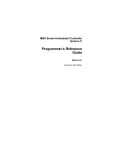
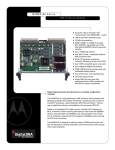
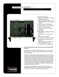
D ATA S H E E T
KEY FEATURES
MPC7410 processor
High-performance L2 cache
High-performance, low-latency
SDRAM subsystem
Up to 2GB of ECC protected
capacity
New DMA capability
Variety of persistent memory
types and capacities
Dual 10/100BaseT Ethernet
CompactPCI Host Slot Processor Board
MCP820
Two USB ports (optional)
Two async serial ports, two
async/sync serial ports, keyboard
and mouse
Single PMC slot
PCI Enhanced IDE (EIDE) controller and floppy disk controller
On-board debug monitor with
self-test diagnostics
The MCP820 series provides
substantial investment
protection to deployed infrastructure by providing an easy
upgrade and migration to
state-of-the-art features and
performance. Utilizing lowpower, high-performance
MPC7410 processors with
2MB of secondary cache,
dual peripheral component
interconnect (PCI) buses
for the on-board peripherals
and a 64-bit bridge to the
CompactPCI® interface, the
MCP820 series packs optimum
performance and functionality
in a single CompactPCI slot.
The MCPTM-01 transition
module provides industry
standard connector access
to a single mouse/keyboard
connector, EIDE and floppy
connectors (internal), one
RJ-45 connector and one 10-pin
header providing access to the
asynchronous serial ports, one
PIM, two RJ-45 connectors for
rear Ethernet and two additional
sync/async serial ports via a
single connector.
Designed with relevant
standards, compatibility and
interoperability in mind, the
MCP820 is compliant with
PICMG® 2.1 (Hot Swap), VITA
36 (PIM), IEEE 1386.1 (PMC)
and Motorola’s high availability
system architecture specifications. The MCP820 supports
booting a complete range
of real-time operating systems
and kernels which may be
purchased from companies
such as Wind River Systems,
Inc. and other leading providers.
Four 32-bit timers, three watchdog timers
See back page
for details
The Motorola MCP820 series is a family of CompactPCI host-slot processor
modules and the first host-slot modules to benefit from Motorola’s PowerPlus III
Architecture. The MCP820 series pushes performance and functionality of the
PowerPlus Architecture to unprecedented levels.
JTAG
L2 Cache
1MB/2MB
MPC7410
PowerPC Architecture Bus 100MHz
Flash A
to 32MB
Harrier
A
Xport
SDRAM Mezz
(1GB Max)
SPD
I 2C
SDRAM Mezz
(1GB Max)
SPD
I2C
VPD
User
Flash B
1MB
UART 0
CompactPCI
J4
PCI Bus B, 33/66 MHz, 64-bit
PCI Bus A, 33 MHz, 64-bit
NVRAM
RTC
UART 1
Ethernet
10/100
Single-wide PMC*
*PMC can run at
66 MHz but will
disable Ethermat
PCI/PCI
Bridge
USB
(optional)
USB0
USB1
PCI-ISA
Bridge
EIDE
Primary
Kbd/Ms
Floppy
CIO
Secondary
Super
I/O
ISA
ESCC
Ethernet
10/100
Front Panel
CompactPCI
J1/2
Harrier
B
CompactFlash
Type I/II
2SyncCom
CompactPCI J3/5
SPECIFICATIONS
PROCESSING SUBSYSTEM
C O M PA C T P C I I N T E R FA C E
Processor: 500 MHz MPC7410 processor
Controller: Intel® 21154
On-chip L1 Cache (I/D): 32K/32K
Address/Data: A32/D32/D64 with parity
High-Performance L2 Cache: 200 MHz parity protected,
PCI Bus Clock: 33/66 MHz, PCI 2.1 compliant
2MB
Signaling: 3.3V output, input defined by VIO
Frontside Bus: 100 MHz
E T H E R N E T I N T E R FA C E
C O N T R O L L E R A N D M E M O RY S U B S Y S T E M
Dynamic Memory: ECC protected synchronous dynamic
RAM
Capacity: Up to four RAM500 mezzanines yielding 2GB
maximum capacity
Additional Functions: Dual DMA engine—See the
Harrier ASIC Programmer’s Reference Guide for details;
dual multi-processor interrupt controller (MPIC).
One DMA engine per Harrier controller.
Single Cycle Accesses: 10 read/5 write
Read Burst Mode: 8-1-1-1 idle; 3-1-1-1 aligned page hit
(CL3)
Write Burst Mode: 4-1-1-1 idle; 3-1-1-1 aligned page hit
2
MCP820
Controller: Dual Intel® 82559ER
Interface Speed: 10/100Mbps
PCI Local bus DMA: Yes, with PCI burst
Connector: One RJ-45 on front panel, one TM port RJ-45
via Jx
P E R S I S T E N T M E M O RY
FLOPPY
Flash Capacity (bootable): 1MB via two 32-pin PLCC
Controller: PC97317
sockets; additional 32MB surface mount; selectable via
Compatible Controllers: DP8473, 765A, N82077
reset vector
CompactFlash: Single Type I/II memory card socket for
large capacity needs (50-pin socket)
Configuration: 3.5” 2.88MB and 1.44MB; 5.25” 1.2MB
Connector: Routed to J3, 34-pin header on MCPTM-01
Controller: W83C554
Interface: ATA, true IDE mode
M O U S E / K E Y B O A R D I N T E R FA C E
NVRAM: 32KB total capacity, 4KB available for user data
Controller: PC97317
Cell Storage Life: 50 years at 55° C
Connector: Routed to J3, 6-pin mini DIN on MCPTM-01
Cell Capacity Life: 10 years at 100% duty cycle
Removable Battery: Yes
IEEE P1386.1 PCI MEZZANINE CARD SLOT
SROM/Serial EEPROM: AT93C46 SROMs for Ethernet
Address/Data: A32/D32/D64, PMC PN1, PN2, PN3, PN4
configuration; two 8KB dual-address I2C devices for vital
connectors
product data (VPD) and user configuration data; separate
PCI Bus Clock: 33 MHz or 66 MHz
256 byte standard I2C serial EEPROMs (on mezzanines)
for memory VPD
Signaling: 3.3V
Power: +3.3V, +5V, 12V, 7.5 watts maximum per PMC slot
A S Y N C H R O N O U S S E R I A L P O RT S
Module Types: Basic, single-wide, front panel I/O
or J3 I/O
Controller: PC97317
Number of Ports: Two, 16550-compatible
Configuration: EIA-574-DTE
Async Baud Rate, bps max.: 38.4K EIA-232, 115Kb/s raw
Connector (COM1): Front panel RJ-45, also RJ-45 on
MCPTM-01
COUNTERS/TIMERS
TOD Clock Device: MT48T37, 32KB NVRAM
Real-Time Timers/Counters: Four 32-bit programmable
Watchdog Timers: Three, time-out generates reset
Connector (COM2): Routed to J3, 10-pin header on
MCPTM-01
POWER REQUIREMENTS
(not including power required by PMC, PIM or SIMs)
S Y N C H R O N O U S S E R I A L P O RT S
Controller: Z85230/Z8536
+3.3V ±5%
MCP820-500:
Number of Ports: Two
+5V ±5%
12V ±5%
2.6 A typ.
2.8 A typ.
15 mA typ.
3.5 A max.
3.75 A max. 20 mA max.
Configuration: TTL to P2 (both ports), SIM on
MCPTM-01
BOARD SIZE
Baud Rate, bps max.: 2.5MB sync, 38.4KB async
Height: 233.4 mm (9.2 in.)
Oscillator Clock Rate (PCLK): 10 MHz/5 MHz
Depth: 160.0 mm (6.3 in.)
Connector: Routed to J3, HD-50 on MCPTM-01
Front Panel Height: 261.8 mm (10.3 in.)
Width: 19.8 mm (0.8 in.)
E I D E I N T E R FA C E
Max. Component Height: 14.8 mm (0.6 in.)
Controller: W83C554F
Connector: Routed to J5, one 40-pin header on
MCPTM-01; plus on-board CompactFlash
F R O N T PA N E L D E TA I L A N D C O N T E N T
LED Indicators: Board FAIL, CPU Activity and Hot Swap
Status
USB
Recessed Switches: Reset and Abort
Controller: USS312
Connectors: Two Series A receptacles on front panel,
also routed to J5
MCP820
3
TRANSITION MODULES
TRANSITION MODULE I/O CONNECTORS
BOARD SIZE
Asynchronous Serial Ports: RJ-45 labeled as COM1
Height: 233.4 mm (9.2 in.)
Synchronous Serial Ports: Two (Serial 3 and Serial 4).
Depth: 80.0 mm (3.1 in.)
User configurable via the installation of SIMs. Two 60-
Front Panel Height: 261.8 mm (10.3 in.)
pin connectors on planar for installation of two serial
interface modules. Single 50-pin external connector with
Width: 19.8 mm (0.8 in.)
Y-cable adapter.
Mouse/Keyboard: 6-pin circular female mini DIN
Floppy: 34-pin header
EIDE: One 40-pin header
ALL MODULES
E N V I R O N M E N TA L
Operating
Temperature:
SAFETY
Storage/Transit
0° C to +55° C, forced –40° C to +85° C
All printed wiring boards (PWBs) are manufactured
with a flammability rating of 94V-0 by UL recognized
manufacturers.
air cooling exit air
Humidity (NC): 10% to 80%
10% to 90%
Vibration:
0.5 G RMS,
6.0 Gs RMS,
E L E C T R O M A G N E T I C C O M PAT I B I L I T Y ( E M C )
20–2000 Hz random
20–2000 Hz random
Intended for use in systems meeting the following
regulations:
D E M O N S T R AT E D M T B F
U.S.: FCC Part 15, Subpart B, Class A (non-residential)
(based on a sample of eight boards in accelerated stress
Canada: ICES-003, Class A (non-residential)
environment)
Mean: 190,509 hours
95% Confidence: 107,681 hours
Motorola board products are tested in a representative
system to the following standards, results pending:
CE Mark per European EMC Directive 89/336/EEC with
Amendments; Emissions: EN55022 Class B; Immunity:
EN55024
4
MCP820
O R D E R I N G I N F O R M AT I O N
Part Number
Description
MCP820-500
500 MHz MPC7410 with support for USB, order memory separate
MCP820-505-CK
500 MHz MPC7410 without support for USB, order memory separate
(configurable spare)
Related Products
MCPTM-01
Transition module: One RJ-45 async serial port connector, one HD-50 sync/async
serial port connector (Y-cable splits to two HD-26 connectors), one mouse/
keyboard 6-pin mini DIN, PIM
RAM500-005
128MB memory mezzanine, MCP820/MCP765/MVME5100, top
RAM500-015
128MB memory mezzanine, MCP820/MCP765/MVME5100, bottom
RAM500-006
256MB memory mezzanine, MCP820/MCP765/MVME5100, top
RAM500-016
256MB memory mezzanine, MCP820/MCP765/MVME5100, bottom
RAM500-010
512MB memory mezzanine, MCP820/MCP765/MVME5100, top
RAM500-020
512MB memory mezzanine, MCP820/MCP765/MVME5100, bottom
CFLASH-xxx
CompactFlash memory card (where xxx = number of MB)
Documentation
MCP820A/IH
MCP820 Installation and Use (includes MCPTM-01 information)
MCP820A/PG
MCP820 Programmer’s Reference Guide
PPCBUGA1/UM and
PPCBUGA2/UM
PPCBug Firmware Package User’s Manual, volumes 1 and 2
PPCDIAA/UM
PPCBug Diagnostics Manual
Documentation is available for online viewing and ordering at www.motorola.com/computer/literature
Future RoHS Status
This product is being redesigned for 5/6 RoHS
compliance. When the RoHS compliant
version is available, the RoHS designator will
be updated accordingly.
S O L U T I O N S E RV I C E S
Motorola provides a portfolio of solution services optimized to meet your needs throughout the product lifecycle.
Design services help speed time-to-market. Deployment services include global 24x7 technical support. Renewal
services enable product longevity and technology refresh. And solution extras include enhanced warranty and repairs.
Sales Offices
Tempe, AZ U.S.A. 1 800 759 1107 or +1 602 438 5720
Paris, France +33 1 69 35 25 88
Munich, Germany +49 89 608 14-0
Loughborough, UK +44 1509 634300
Tel Aviv, Israel +972 3 568 4385
Shanghai, China +86 215292 5693
Tokyo, Japan +81 3 5424 3101
Hong Kong, China +852 2966 3209
This document identifies products, their specifications, and their characteristics, which may be suitable for certain applications. It does not constitute an offer to
sell or a commitment of present or future availability, and should not be relied upon to state the terms and conditions, including warranties and disclaimers thereof, on
which Motorola may sell products. A prospective buyer should exercise its own independent judgment to confirm the suitability of the products for particular applications.
Motorola reserves the right to make changes, without notice, to any products or information herein which will, in its sole discretion, improve reliability, function, or design.
Motorola does not assume any liability arising out of the application or use of any product or circuit described herein; neither does it convey any license under its patent or
other intellectual property rights or under others. This disclaimer extends to any prospective buyer, and it includes Motorola’s licensee, licensee’s transferees, and licensee’s
customers and users. Availability of some of the products and services described herein may be restricted in some locations.
www.motorola.com/computing
MOTOROLA and the Stylized M Logo are registered in the U.S. Patent and Trademark Office. PICMG and CompactPCI are registered trademarks of the PCI Industrial
Computer Manufacturers Group. PowerPC is a trademark of IBM Corp. and used under license. Intel is a registered trademark of Intel Corporation or its subsidiaries in the
U.S. and other countries. All other product or service names are the property of their respective owners. © Motorola, Inc. 2005
MCP820-D4 10/05