1
Power Hawk Series 600
Diskless Systems Administrator’s Guide
(Title was formerly “Diskless Systems Administrator’s Guide”)
0891080-020
June 2001
Copyright 2001 by Concurrent Computer Corporation. All rights reserved. This publication or any part thereof is
intended for use with Concurrent Computer Corporation products by Concurrent Computer Corporation personnel,
customers, and end–users. It may not be reproduced in any form without the written permission of the publisher.
The information contained in this document is believed to be correct at the time of publication. It is subject to change
without notice. Concurrent Computer Corporation makes no warranties, expressed or implied, concerning the
information contained in this document.
To report an error or comment on a specific portion of the manual, photocopy the page in question and mark the
correction or comment on the copy. Mail the copy (and any additional comments) to Concurrent Computer Corporation, 2881 Gateway Drive Pompano Beach, FL 33069. Mark the envelope “Attention: Publications Department.”
This publication may not be reproduced for any other reason in any form without written permission of the publisher.
UNIX is a registered trademark of the Open Group.
Ethernet is a trademark of Xerox Corporation.
PowerMAX OS is a registered trademark of Concurrent Computer Corporation.
Power Hawk and PowerStack are trademarks of Concurrent Computer Corporation.
Other products mentioned in this document are trademarks, registered trademarks, or trade names of the
manufactures or marketers of the product with which the marks or names are associated.
Printed in U. S. A.
Revision History:
Level:
Effective With:
Original Issue
000
PowerMAX OS Release 4.3
Previous Issue
010
PowerMAX OS Release 4.3, P2
Current Issue
020
PowerMAX OS Release 5.1
Preface
Scope of Manual
Intended for system administrators responsible for configuring and administering diskless
system configurations. A companion manual, the Power Hawk Series 600 CloselyCoupled Programming Guide, is intended for programmers writing applications which are
distributed across multiple single board computers (SBCs).
Structure of Manual
This manual consists of a title page, this preface, a master table of contents, nine chapters,
local tables of contents for the chapters, five appendices, glossary of terms, and an index.
• Chapter 1, Introduction, contains an overview of Diskless Topography, Diskless boot basics, configuration toolsets, definition of terms, hardware
overview, diskless implementation, configuring diskless systems and
licensing details.
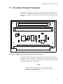
• Chapter 2, MTX SBC Hardware Considerations, provides equipment specifications, hardware preparation, installation instruction and general operating data.
• Chapter 3, VME SBC Hardware Considerations, provides equipment specifications, hardware preparation, installation instruction and general operating data.
• Chapter 4, MCP750 Hardware Considerations, provides equipment specifications, hardware preparation, installation instruction and general operating data.
• Chapter 5, Net Boot System Administration, provides an overview of the
steps that must be followed in configuring a loosely-coupled system (LCS)
configuration.
• Chapter 6, VME Boot System Administration, provides an overview of the
steps that must be followed in configuring a closely-coupled system (CCS)
configuration.
• Chapter 7, Flash Boot System Administration, This chapter is a guide to
configuring a diskless single board computer (SBC) to boot PowerMAX
OS from flash memory.
• Chapter 8, Modifying VME Space Allocation. describes how a system
administrator can modify the default VME space configuration on CloselyCoupled systems (CCS).
iii
Power Hawk Series 600 Diskless Systems Administrator’s Guide
• Chapter 9, Debugging Tools, covers the tools available for system debugging on a diskless client. The tools that are available to debug a diskless
client depend on the diskless system architecture.
• Appendix A provides a copy of the vmebootconfig(1m) man page.
• Appendix B provides a copy of the netbootconfig(1m) man page.
• Appendix C provides a copy of the mkvmebstrap(1m) man page.
• Appendix D provides a copy of the mknetbstrap(1m) man page.
• Appendix E provides instructions on how to add a local disk.
• Appendix F provides instructions on how to make a client system run in
NFS File Server mode.
• Glossary explains the abbreviations, acronyms, and terms used throughout
the manual.
The index contains an alphabetical list of all paragraph formats, character formats, cross
reference formats, table formats, and variables.
Syntax Notation
The following notation is used throughout this guide:
iv
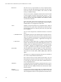
italic
Books, reference cards, and items that the user must specify
appear in italic type. Special terms may also appear in italic.
list bold
User input appears in list bold type and must be entered
exactly as shown. Names of directories, files, commands, options
and man page references also appear in list bold type.
list
Operating system and program output such as prompts and messages and listings of files and programs appears in list type.
[]
Brackets enclose command options and arguments that are
optional. You do not type the brackets if you choose to specify
such option or arguments
Preface
Referenced Publications
Title
Pubs No.
Concurrent Computer Corporation Manuals
System Administration Manual (Volume 1)
0890429
System Administration Manual (Volume 2)
0890430
Power Hawk Series 600 Closely-Coupled Programming Guide
0891081
Power Hawk Series 600 PowerMAX OS (Version x.x) Release Notes
0891058-reln
(reln = OS release
number, e.g. 5.1)
MTX Single Board Computer (SBC) Manuals (See Note below)
MTX Series Motherboard Installation and Use Manual
MTXA/IH1
MTX Series Motherboard Computer Programmer’s Reference Guide
MTXA/PG
PPCBug Firmware Package User’s Manual (Parts 1)
PPCUGA1/UM
PPCBug Firmware Package User’s Manual (Part 2)
PPCUGA2/UM
PPC1Bug Diagnostics Manual
PPCDIAA/UM
MTX PCI Series Single Board Computer (SBC) Manuals (See Note below)
MTX PCI Series Motherboard Installation and Use Manual
MTXPCI/IH1
MTX PCI Series Programmer’s Reference Guide
MTXPCIA/PG
PPCBug Firmware Package User’s Manual (Parts 1)
PPCUGA1/UM
PPCBug Firmware Package User’s Manual (Part 2)
PPCUGA2/UM
PPC1Bug Diagnostics Manual
PPCDIAA/UM
Note: The Motorola documents are available on the following web site at:
http://www.mcg.mot.com/literature
Title
Pubs No.
VME Single Board Computer (SBC) Manuals (See Note below)
MVME2600 Series Single Board Computer Installation and Use Manual
V2600A/IH1
MVME4600 Series Single Board Computer Installation and Use
VMV4600A/IH1
PPCBug Firmware Package User’s Manual (Parts 1)
PPCUGA1/UM
PPCBug Firmware Package User’s Manual (Part 2)
PPCUGA2/UM
PPC1Bug Diagnostics Manual
PPCDIAA/UM
MCP750 Single Board Computer (SBC) Manuals (See Note below)
MCP750 CompactPCI Single Board Computer Installation and Use
MCP750A/IH1
MCP750 CompactPCI Single Board Computer Programmer’s
Reference Guide
MCP750A/PG
PPCBug Firmware Package User’s Manual (Parts 1)
PPCUGA1/UM
v
Power Hawk Series 600 Diskless Systems Administrator’s Guide
PPCBug Firmware Package User’s Manual (Part 2)
PPCUGA2/UM
PPC1Bug Diagnostics Manual
PPCDIAA/UM
Manufacturers’ Documents (See Note below)
MCP750TM RISC Microprocessor Technical Summary
MCP750/D
MCP750TM RISC Microprocessor User’s Manual
MCP750UM/AD
Note: The Motorola documents are available on the following web site at:
http://www.mcg.mot.com/literature
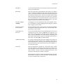
Related Specifications
Title
Pubs No.
Specifications
vi
IEEE - Common Mezzanine Card Specification (CMC)
P1386 Draft 2.0
IEEE - PCI Mezzanine Card Specification (CMC)
P1386.1 Draft 2.0
Compact PCI Specification
CPCI Rev 2.1
Dated 9/2/97
Contents
Contents
Chapter 1 Introduction
Overview . . . . . . . . . . . . . . . . . . . . . . . . . . . . . . . . . . . . . . . . . . . . . . . . . . . . . . . . . .
Diskless Topography . . . . . . . . . . . . . . . . . . . . . . . . . . . . . . . . . . . . . . . . . . . . .
Diskless Boot Basics . . . . . . . . . . . . . . . . . . . . . . . . . . . . . . . . . . . . . . . . . . . . .
Configuration Toolsets . . . . . . . . . . . . . . . . . . . . . . . . . . . . . . . . . . . . . . . . . . . .
Definitions . . . . . . . . . . . . . . . . . . . . . . . . . . . . . . . . . . . . . . . . . . . . . . . . . . . . . . . . .
Hardware Overview . . . . . . . . . . . . . . . . . . . . . . . . . . . . . . . . . . . . . . . . . . . . . . . . . .
MTX SBC Features . . . . . . . . . . . . . . . . . . . . . . . . . . . . . . . . . . . . . . . . . . . . . .
MTX II (MTX604-070) SBC Features. . . . . . . . . . . . . . . . . . . . . . . . . . . . . . . .
VME SBC Features . . . . . . . . . . . . . . . . . . . . . . . . . . . . . . . . . . . . . . . . . . . . . .
MCP750 SBC Features . . . . . . . . . . . . . . . . . . . . . . . . . . . . . . . . . . . . . . . . . . .
Diskless Implementation . . . . . . . . . . . . . . . . . . . . . . . . . . . . . . . . . . . . . . . . . . . . . .
Virtual Root . . . . . . . . . . . . . . . . . . . . . . . . . . . . . . . . . . . . . . . . . . . . . . . . . . . .
Boot Image Creation and Characteristics . . . . . . . . . . . . . . . . . . . . . . . . . . . . . .
MEMFS Root Filesystem . . . . . . . . . . . . . . . . . . . . . . . . . . . . . . . . . . . . . . . . . .
Booting . . . . . . . . . . . . . . . . . . . . . . . . . . . . . . . . . . . . . . . . . . . . . . . . . . . . . . . .
VME Boot . . . . . . . . . . . . . . . . . . . . . . . . . . . . . . . . . . . . . . . . . . . . . . . . . .
VME Booting in Remote Clusters . . . . . . . . . . . . . . . . . . . . . . . . . . . . . . .
Net Boot . . . . . . . . . . . . . . . . . . . . . . . . . . . . . . . . . . . . . . . . . . . . . . . . . . .
Flash Boot . . . . . . . . . . . . . . . . . . . . . . . . . . . . . . . . . . . . . . . . . . . . . . . . . .
VME Networking . . . . . . . . . . . . . . . . . . . . . . . . . . . . . . . . . . . . . . . . . . . . . . . .
Remote File Sharing . . . . . . . . . . . . . . . . . . . . . . . . . . . . . . . . . . . . . . . . . . . . . .
Shared Memory . . . . . . . . . . . . . . . . . . . . . . . . . . . . . . . . . . . . . . . . . . . . . . . . .
Swap Space. . . . . . . . . . . . . . . . . . . . . . . . . . . . . . . . . . . . . . . . . . . . . . . . . . . . .
Configuring Diskless Systems . . . . . . . . . . . . . . . . . . . . . . . . . . . . . . . . . . . . . . . . . .
Closely-Coupled System Hardware Prerequisites . . . . . . . . . . . . . . . . . . . . . . .
Loosely-Coupled System Hardware Prerequisites . . . . . . . . . . . . . . . . . . . . . . .
Disk Space Requirements. . . . . . . . . . . . . . . . . . . . . . . . . . . . . . . . . . . . . . . . . .
Software Prerequisites . . . . . . . . . . . . . . . . . . . . . . . . . . . . . . . . . . . . . . . . . . . .
Installation Guidelines . . . . . . . . . . . . . . . . . . . . . . . . . . . . . . . . . . . . . . . . . . . . . . . .
Licensing Information . . . . . . . . . . . . . . . . . . . . . . . . . . . . . . . . . . . . . . . . . . . . . . . .
1- 1
1-1
1-4
1-6
1-7
1-10
1-11
1-11
1-12
1-13
1-14
1-14
1-14
1-15
1-16
1-16
1-17
1-17
1-18
1-19
1-21
1-25
1-25
1-27
1-27
1-28
1-28
1-29
1-29
1-30
Chapter 2 MTX SBC Hardware Considerations
Introduction . . . . . . . . . . . . . . . . . . . . . . . . . . . . . . . . . . . . . . . . . . . . . . . . . . . . . . . .
Unpacking Instructions . . . . . . . . . . . . . . . . . . . . . . . . . . . . . . . . . . . . . . . . . . . . . . .
Hardware Configuration . . . . . . . . . . . . . . . . . . . . . . . . . . . . . . . . . . . . . . . . . . . . . .
MTX Motherboard Preparation . . . . . . . . . . . . . . . . . . . . . . . . . . . . . . . . . . . . . . . . .
Cache Mode Control (J15) . . . . . . . . . . . . . . . . . . . . . . . . . . . . . . . . . . . . . . . . .
Flash Bank Selection (J37) . . . . . . . . . . . . . . . . . . . . . . . . . . . . . . . . . . . . . . . . . . . .
Power Control for ATX Power Supply (J27) . . . . . . . . . . . . . . . . . . . . . . . . . . .
Hardware/Firmware Disable of SCSI (J36) . . . . . . . . . . . . . . . . . . . . . . . . . . . .
Remote Status and Control. . . . . . . . . . . . . . . . . . . . . . . . . . . . . . . . . . . . . . . . .
Hardware Installation. . . . . . . . . . . . . . . . . . . . . . . . . . . . . . . . . . . . . . . . . . . . . . . . .
DIMM Memory Installation . . . . . . . . . . . . . . . . . . . . . . . . . . . . . . . . . . . . . . . . . . .
2-1
2-2
2-2
2-2
2-4
2-4
2-5
2-5
2-6
2-6
2-6
vii
Power Hawk Series 600 Diskless Systems Administrator’s Guide
PCI Adapter Installation. . . . . . . . . . . . . . . . . . . . . . . . . . . . . . . . . . . . . . . . . . . . . . .
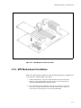
PMC Module Installation. . . . . . . . . . . . . . . . . . . . . . . . . . . . . . . . . . . . . . . . . . . . . .
MTX Motherboard Installation . . . . . . . . . . . . . . . . . . . . . . . . . . . . . . . . . . . . . . . . .
MTX Motherboard . . . . . . . . . . . . . . . . . . . . . . . . . . . . . . . . . . . . . . . . . . . . . . .
MTX Series Connectors. . . . . . . . . . . . . . . . . . . . . . . . . . . . . . . . . . . . . . . . . . . . . . .
Front Panel Function Header . . . . . . . . . . . . . . . . . . . . . . . . . . . . . . . . . . . . . . .
Rear Panel Keyboard/Mouse Connectors . . . . . . . . . . . . . . . . . . . . . . . . . . . . . .
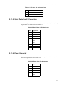
10BaseT/100BaseT Connector . . . . . . . . . . . . . . . . . . . . . . . . . . . . . . . . . . . . . .
AUI Connector . . . . . . . . . . . . . . . . . . . . . . . . . . . . . . . . . . . . . . . . . . . . . . . . . .
Serial Ports 1 and 2 Connectors . . . . . . . . . . . . . . . . . . . . . . . . . . . . . . . . . . . . .
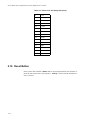
Power Connector. . . . . . . . . . . . . . . . . . . . . . . . . . . . . . . . . . . . . . . . . . . . . . . . .
Reset Button . . . . . . . . . . . . . . . . . . . . . . . . . . . . . . . . . . . . . . . . . . . . . . . . . . . . . . . .
2-8
2-9
2-11
2-12
2-13
2-13
2-13
2-14
2-14
2-15
2-15
2-16
Chapter 3 VME SBC Hardware Considerations
Introduction . . . . . . . . . . . . . . . . . . . . . . . . . . . . . . . . . . . . . . . . . . . . . . . . . . . . . . . .
Unpacking Instructions . . . . . . . . . . . . . . . . . . . . . . . . . . . . . . . . . . . . . . . . . . . . . . .
Backplane Daisy-Chain Jumpers . . . . . . . . . . . . . . . . . . . . . . . . . . . . . . . . . . . . . . . .
MVME2604 Base Board Preparation . . . . . . . . . . . . . . . . . . . . . . . . . . . . . . . . . . . .
VMEbus System Controller Selection (J22). . . . . . . . . . . . . . . . . . . . . . . . . . . .
Flash Bank Selector (J10) . . . . . . . . . . . . . . . . . . . . . . . . . . . . . . . . . . . . . . . . . .
MVME4604 Base Board Preparation . . . . . . . . . . . . . . . . . . . . . . . . . . . . . . . . . . . .
VMEbus System Controller Selection (J5). . . . . . . . . . . . . . . . . . . . . . . . . . . . .
Flash Bank Selection (J2) . . . . . . . . . . . . . . . . . . . . . . . . . . . . . . . . . . . . . . . . . .
MVME761 Transition Module Preparation . . . . . . . . . . . . . . . . . . . . . . . . . . . . . . . .
Configuration of Serial Ports 1 and 2 . . . . . . . . . . . . . . . . . . . . . . . . . . . . . . . . .
Configuration of Serial Ports 3 and 4 . . . . . . . . . . . . . . . . . . . . . . . . . . . . . . . . .
Three-Row P2 Adapter Preparation . . . . . . . . . . . . . . . . . . . . . . . . . . . . . . . . . . . . . .
Optional Five-Pin P2 Adapter Preparation. . . . . . . . . . . . . . . . . . . . . . . . . . . . . . . . .
Base Board Connectors . . . . . . . . . . . . . . . . . . . . . . . . . . . . . . . . . . . . . . . . . . . . . . .
VME Connector P2 (MVME761 Mode) . . . . . . . . . . . . . . . . . . . . . . . . . . . . . .
Serial Ports 1 and 2 (MVME761 I/O Mode) . . . . . . . . . . . . . . . . . . . . . . . . . . .
Serial Ports 3 and 4 (MVME761 I/O Mode) . . . . . . . . . . . . . . . . . . . . . . . . . . .
Parallel Connector (MVME761 I/O Mode) . . . . . . . . . . . . . . . . . . . . . . . . . . . .
Ethernet 10Base-T /100Base-T Connector . . . . . . . . . . . . . . . . . . . . . . . . . . . . .
P2 Adapter Connectors . . . . . . . . . . . . . . . . . . . . . . . . . . . . . . . . . . . . . . . . . . . . . . .
Reset Button . . . . . . . . . . . . . . . . . . . . . . . . . . . . . . . . . . . . . . . . . . . . . . . . . . . . . . . .
Abort Button . . . . . . . . . . . . . . . . . . . . . . . . . . . . . . . . . . . . . . . . . . . . . . . . . . . . . . .
3-1
3-2
3-2
3-4
3-6
3-6
3-7
3-9
3-9
3-10
3-10
3-10
3-13
3-14
3-15
3-15
3-15
3-15
3-16
3-16
3-19
3-23
3-23
Chapter 4 MCP750 Hardware Considerations
Introduction . . . . . . . . . . . . . . . . . . . . . . . . . . . . . . . . . . . . . . . . . . . . . . . . . . . . . . . .
Unpacking Instructions . . . . . . . . . . . . . . . . . . . . . . . . . . . . . . . . . . . . . . . . . . . . . . .
Hardware Configuration. . . . . . . . . . . . . . . . . . . . . . . . . . . . . . . . . . . . . . . . . . . . . . .
MCP750 Base Board Preparation . . . . . . . . . . . . . . . . . . . . . . . . . . . . . . . . . . . . . . .
Flash Bank Selection (J6) . . . . . . . . . . . . . . . . . . . . . . . . . . . . . . . . . . . . . . . . . .
TMCP700 Transition Module Preparation. . . . . . . . . . . . . . . . . . . . . . . . . . . . . . . . .
Serial Ports 1 and 2 . . . . . . . . . . . . . . . . . . . . . . . . . . . . . . . . . . . . . . . . . . . . . . .
Configuration of Serial Ports 3 and 4 . . . . . . . . . . . . . . . . . . . . . . . . . . . . . . . . .
Hardware Installation . . . . . . . . . . . . . . . . . . . . . . . . . . . . . . . . . . . . . . . . . . . . . . . . .
ESD Precautions . . . . . . . . . . . . . . . . . . . . . . . . . . . . . . . . . . . . . . . . . . . . . . . . .
Compact FLASH Memory Card Installation . . . . . . . . . . . . . . . . . . . . . . . . . . . . . . .
RAM300 Memory Mezzanine Installation . . . . . . . . . . . . . . . . . . . . . . . . . . . . . . . .
viii
4-1
4-1
4-2
4-2
4-4
4-4
4-6
4-6
4-7
4-8
4-8
4-10
Contents
PMC Module Installation . . . . . . . . . . . . . . . . . . . . . . . . . . . . . . . . . . . . . . . . . . . . .
MCP750 Module Installation . . . . . . . . . . . . . . . . . . . . . . . . . . . . . . . . . . . . . . . . . .
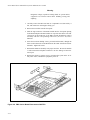
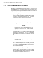
TMCP700 Transition Module Installation. . . . . . . . . . . . . . . . . . . . . . . . . . . . . . . . .
4-11
4-13
4-14
Chapter 5 Netboot System Administration
Configuration Overview . . . . . . . . . . . . . . . . . . . . . . . . . . . . . . . . . . . . . . . . . . . . . .
Installing a Loosely-Coupled System. . . . . . . . . . . . . . . . . . . . . . . . . . . . . . . . .
Installing Additional Boards . . . . . . . . . . . . . . . . . . . . . . . . . . . . . . . . . . . . . . .
SBC Configuration . . . . . . . . . . . . . . . . . . . . . . . . . . . . . . . . . . . . . . . . . . . . . . . . . .
PPCBug Overview . . . . . . . . . . . . . . . . . . . . . . . . . . . . . . . . . . . . . . . . . . . . . . .
Setting the Hardware Clock . . . . . . . . . . . . . . . . . . . . . . . . . . . . . . . . . . . . . . . .
PPCBug env Setup . . . . . . . . . . . . . . . . . . . . . . . . . . . . . . . . . . . . . . . . . . . . . . .
PPCBug niot Setup . . . . . . . . . . . . . . . . . . . . . . . . . . . . . . . . . . . . . . . . . . . . . . .
Client Configuration . . . . . . . . . . . . . . . . . . . . . . . . . . . . . . . . . . . . . . . . . . . . . . . . .
Configuration Tables . . . . . . . . . . . . . . . . . . . . . . . . . . . . . . . . . . . . . . . . . . . . .
Nodes Table. . . . . . . . . . . . . . . . . . . . . . . . . . . . . . . . . . . . . . . . . . . . . . . . .
Hosts Table . . . . . . . . . . . . . . . . . . . . . . . . . . . . . . . . . . . . . . . . . . . . . . . . .
Configuring Clients Using netbootconfig. . . . . . . . . . . . . . . . . . . . . . . . . . . . . .
Creating and Removing a Client Configuration . . . . . . . . . . . . . . . . . . . . .
Subsystem Support . . . . . . . . . . . . . . . . . . . . . . . . . . . . . . . . . . . . . . . . . . .
Customizing the Basic Client Configuration. . . . . . . . . . . . . . . . . . . . . . . . . . . . . . .
Modifying the Kernel Configuration . . . . . . . . . . . . . . . . . . . . . . . . . . . . . . . . .
kernel.modlist.add . . . . . . . . . . . . . . . . . . . . . . . . . . . . . . . . . . . . . . . . . . . .
mknetbstrap . . . . . . . . . . . . . . . . . . . . . . . . . . . . . . . . . . . . . . . . . . . . . . . . .
config utility . . . . . . . . . . . . . . . . . . . . . . . . . . . . . . . . . . . . . . . . . . . . . . . .
idtuneobj . . . . . . . . . . . . . . . . . . . . . . . . . . . . . . . . . . . . . . . . . . . . . . . . . . .
Custom Configuration Files . . . . . . . . . . . . . . . . . . . . . . . . . . . . . . . . . . . . . . . .
S25client and K00client rc Scripts . . . . . . . . . . . . . . . . . . . . . . . . . . . . . . .
memfs.inittab and inittab Tables . . . . . . . . . . . . . . . . . . . . . . . . . . . . . . . . .
vfstab Table . . . . . . . . . . . . . . . . . . . . . . . . . . . . . . . . . . . . . . . . . . . . . . . . .
kernel.modlist.add Table . . . . . . . . . . . . . . . . . . . . . . . . . . . . . . . . . . . . . . .
memfs.files.add Table . . . . . . . . . . . . . . . . . . . . . . . . . . . . . . . . . . . . . . . . .
Modifying Configuration Table Settings . . . . . . . . . . . . . . . . . . . . . . . . . . . . . .
Nodes Table. . . . . . . . . . . . . . . . . . . . . . . . . . . . . . . . . . . . . . . . . . . . . . . . .
Launching Applications . . . . . . . . . . . . . . . . . . . . . . . . . . . . . . . . . . . . . . . . . . .
Launching an Application (Embedded Client) . . . . . . . . . . . . . . . . . . . . . .
Launching an Application for NFS Clients. . . . . . . . . . . . . . . . . . . . . . . . .
Booting and Shutdown . . . . . . . . . . . . . . . . . . . . . . . . . . . . . . . . . . . . . . . . . . . . . . .
The Boot Image . . . . . . . . . . . . . . . . . . . . . . . . . . . . . . . . . . . . . . . . . . . . . . . . .
Creating the Boot Image. . . . . . . . . . . . . . . . . . . . . . . . . . . . . . . . . . . . . . . . . . .
Examples on Creating the Boot Image . . . . . . . . . . . . . . . . . . . . . . . . . . . .
Net Booting . . . . . . . . . . . . . . . . . . . . . . . . . . . . . . . . . . . . . . . . . . . . . . . . . . . .
Netboot Using NBO . . . . . . . . . . . . . . . . . . . . . . . . . . . . . . . . . . . . . . . . . .
Boot Error Codes. . . . . . . . . . . . . . . . . . . . . . . . . . . . . . . . . . . . . . . . . . . . .
Verifying Boot Status . . . . . . . . . . . . . . . . . . . . . . . . . . . . . . . . . . . . . . . . . . . . .
Shutting Down the Client . . . . . . . . . . . . . . . . . . . . . . . . . . . . . . . . . . . . . . . . . .
5-1
5-1
5-2
5-2
5-3
5-3
5-4
5-5
5-6
5-6
5-7
5-8
5-8
5-9
5-10
5-10
5-11
5-11
5-12
5-12
5-12
5-13
5-14
5-15
5-16
5-16
5-17
5-18
5-18
5-21
5-21
5-22
5-22
5-23
5-24
5-24
5-25
5-25
5-26
5-28
5-28
Chapter 6 VME Boot System Administration
Overview . . . . . . . . . . . . . . . . . . . . . . . . . . . . . . . . . . . . . . . . . . . . . . . . . . . . . . . . . .
Cluster Configuration Overview . . . . . . . . . . . . . . . . . . . . . . . . . . . . . . . . . . . . . . . .
Installing the Local and Remote Clusters. . . . . . . . . . . . . . . . . . . . . . . . . . . . . .
6-1
6-1
6-2
ix
Power Hawk Series 600 Diskless Systems Administrator’s Guide
How To Boot the Local Cluster . . . . . . . . . . . . . . . . . . . . . . . . . . . . . . . . . . . . .
How To Boot Each Remote Cluster . . . . . . . . . . . . . . . . . . . . . . . . . . . . . . . . . .
Installing Additional Boards and Clusters . . . . . . . . . . . . . . . . . . . . . . . . . . . . .
SBC Configuration. . . . . . . . . . . . . . . . . . . . . . . . . . . . . . . . . . . . . . . . . . . . . . . . . . .
Hardware Jumpers . . . . . . . . . . . . . . . . . . . . . . . . . . . . . . . . . . . . . . . . . . . . . . .
Backplane Daisy-Chain Jumpers. . . . . . . . . . . . . . . . . . . . . . . . . . . . . . . . .
NVRAM Modifications . . . . . . . . . . . . . . . . . . . . . . . . . . . . . . . . . . . . . . . . . . .
PPCBug Overview. . . . . . . . . . . . . . . . . . . . . . . . . . . . . . . . . . . . . . . . . . . .
Procedure for Installing SBC Boards . . . . . . . . . . . . . . . . . . . . . . . . . . . . .
NVRAM Board Settings . . . . . . . . . . . . . . . . . . . . . . . . . . . . . . . . . . . . . . . . . . .
VME ISA Reg Mapping & VMEbus Slave Image 0 Settings . . . . . . . . . . .
DRAM Window Size and VMEbus Slave Image 1 Settings . . . . . . . . . . . .
Example PPCBUG ENV Configuration . . . . . . . . . . . . . . . . . . . . . . . . . . . . . . .
Example PPCBUG NIOT Configuration . . . . . . . . . . . . . . . . . . . . . . . . . . . . . .
Cluster Configuration. . . . . . . . . . . . . . . . . . . . . . . . . . . . . . . . . . . . . . . . . . . . . . . . .
Configuration Tables. . . . . . . . . . . . . . . . . . . . . . . . . . . . . . . . . . . . . . . . . . . . . .
Clusters Table . . . . . . . . . . . . . . . . . . . . . . . . . . . . . . . . . . . . . . . . . . . . . . .
Nodes Table . . . . . . . . . . . . . . . . . . . . . . . . . . . . . . . . . . . . . . . . . . . . . . . . .
Hosts Table . . . . . . . . . . . . . . . . . . . . . . . . . . . . . . . . . . . . . . . . . . . . . . . . .
Node Configuration Using vmebootconfig(1m) . . . . . . . . . . . . . . . . . . . . . . . . .
Creating and Removing a Client . . . . . . . . . . . . . . . . . . . . . . . . . . . . . . . . .
Subsystem Support . . . . . . . . . . . . . . . . . . . . . . . . . . . . . . . . . . . . . . . . . . .
Slave Shared Memory Support . . . . . . . . . . . . . . . . . . . . . . . . . . . . . . . . . .
System Tunables Modified . . . . . . . . . . . . . . . . . . . . . . . . . . . . . . . . . . . . .
Customizing the Basic Configuration . . . . . . . . . . . . . . . . . . . . . . . . . . . . . . . . . . . .
Modifying the Kernel Configuration . . . . . . . . . . . . . . . . . . . . . . . . . . . . . . . . .
kernel.modlist.add . . . . . . . . . . . . . . . . . . . . . . . . . . . . . . . . . . . . . . . . . . . .
mkvmebstrap . . . . . . . . . . . . . . . . . . . . . . . . . . . . . . . . . . . . . . . . . . . . . . . .
config Utility . . . . . . . . . . . . . . . . . . . . . . . . . . . . . . . . . . . . . . . . . . . . . . . .
idtuneobj . . . . . . . . . . . . . . . . . . . . . . . . . . . . . . . . . . . . . . . . . . . . . . . . . . .
Custom Configuration Files . . . . . . . . . . . . . . . . . . . . . . . . . . . . . . . . . . . . . . . .
S25client and K00client rc Scripts . . . . . . . . . . . . . . . . . . . . . . . . . . . . . . .
Memfs.inittab and Inittab Tables . . . . . . . . . . . . . . . . . . . . . . . . . . . . . . . . .
vfstab Table . . . . . . . . . . . . . . . . . . . . . . . . . . . . . . . . . . . . . . . . . . . . . . . . .
kernel.modlist.add Table . . . . . . . . . . . . . . . . . . . . . . . . . . . . . . . . . . . . . . .
memfs.files.add Table . . . . . . . . . . . . . . . . . . . . . . . . . . . . . . . . . . . . . . . . .
Modifying Configuration Table Settings . . . . . . . . . . . . . . . . . . . . . . . . . . . . . .
Clusters Table . . . . . . . . . . . . . . . . . . . . . . . . . . . . . . . . . . . . . . . . . . . . . . .
Nodes Table . . . . . . . . . . . . . . . . . . . . . . . . . . . . . . . . . . . . . . . . . . . . . . . . .
Launching Applications . . . . . . . . . . . . . . . . . . . . . . . . . . . . . . . . . . . . . . . . . . .
Launching an Application (Embedded Client) . . . . . . . . . . . . . . . . . . . . . .
Launching an Application (NFS Client) . . . . . . . . . . . . . . . . . . . . . . . . . . .
Booting and Shutdown . . . . . . . . . . . . . . . . . . . . . . . . . . . . . . . . . . . . . . . . . . . . . . . .
The Boot Image . . . . . . . . . . . . . . . . . . . . . . . . . . . . . . . . . . . . . . . . . . . . . . . . .
Booting Options . . . . . . . . . . . . . . . . . . . . . . . . . . . . . . . . . . . . . . . . . . . . . . . . .
Creating the Boot Image . . . . . . . . . . . . . . . . . . . . . . . . . . . . . . . . . . . . . . . . . . .
VME Booting . . . . . . . . . . . . . . . . . . . . . . . . . . . . . . . . . . . . . . . . . . . . . . . . . . .
Net Booting. . . . . . . . . . . . . . . . . . . . . . . . . . . . . . . . . . . . . . . . . . . . . . . . . . . . .
Testing Network Boot Using NBO . . . . . . . . . . . . . . . . . . . . . . . . . . . . . . .
Boot Error Codes . . . . . . . . . . . . . . . . . . . . . . . . . . . . . . . . . . . . . . . . . . . . .
Flash Booting . . . . . . . . . . . . . . . . . . . . . . . . . . . . . . . . . . . . . . . . . . . . . . . . . . .
Verifying Boot Status . . . . . . . . . . . . . . . . . . . . . . . . . . . . . . . . . . . . . . . . . . . . .
Shutting Down the Client . . . . . . . . . . . . . . . . . . . . . . . . . . . . . . . . . . . . . . . . . .
x
6-3
6-3
6-4
6-5
6-5
6-5
6-6
6-6
6-7
6-9
6-9
6-11
6-18
6-21
6-22
6-22
6-23
6-25
6-28
6-29
6-29
6-30
6-31
6-33
6-34
6-34
6-35
6-35
6-35
6-36
6-36
6-38
6-38
6-39
6-40
6-40
6-41
6-42
6-45
6-49
6-49
6-49
6-50
6-51
6-52
6-54
6-54
6-55
6-56
6-56
6-58
6-58
6-59
Contents
Chapter 7 Flash Boot System Administration
Overview . . . . . . . . . . . . . . . . . . . . . . . . . . . . . . . . . . . . . . . . . . . . . . . . . . . . . . . . . .
Introduction to Flash Booting . . . . . . . . . . . . . . . . . . . . . . . . . . . . . . . . . . . . . . . . . .
Vmeboot vs. Netboot . . . . . . . . . . . . . . . . . . . . . . . . . . . . . . . . . . . . . . . . . . . . . . . . .
Configuring a Netboot Client to Flash Boot . . . . . . . . . . . . . . . . . . . . . . . . . . . . . . .
Configuring a Vmeboot Client to Flash Boot . . . . . . . . . . . . . . . . . . . . . . . . . . . . . .
Example - Copying PPCBUG To FLASH B . . . . . . . . . . . . . . . . . . . . . . . . . . . . . . .
Example - PPCBUG NIOT Configuration . . . . . . . . . . . . . . . . . . . . . . . . . . . . . . . .
Example - Net Load Using NBH. . . . . . . . . . . . . . . . . . . . . . . . . . . . . . . . . . . . . . . .
Example - Burning Flash Using PFLASH . . . . . . . . . . . . . . . . . . . . . . . . . . . . . . . .
Example - Booting From Flash Using GD . . . . . . . . . . . . . . . . . . . . . . . . . . . . . . . .
Example - Autobooting From Flash . . . . . . . . . . . . . . . . . . . . . . . . . . . . . . . . . . . . .
Tutorial - Configure a Netboot Client to Flashboot. . . . . . . . . . . . . . . . . . . . . . . . . .
7-1
7-1
7-2
7-3
7-4
7-6
7-7
7-8
7-9
7-9
7-10
7-10
Chapter 8 Modifying VME Space Allocation
Overview . . . . . . . . . . . . . . . . . . . . . . . . . . . . . . . . . . . . . . . . . . . . . . . . . . . . . . . . . .
Default VME Configuration . . . . . . . . . . . . . . . . . . . . . . . . . . . . . . . . . . . . . . . . . . .
Reasons to Modify Defaults . . . . . . . . . . . . . . . . . . . . . . . . . . . . . . . . . . . . . . . . . . .
Limitations. . . . . . . . . . . . . . . . . . . . . . . . . . . . . . . . . . . . . . . . . . . . . . . . . . . . . . . . .
Changing The Default VME Configuration . . . . . . . . . . . . . . . . . . . . . . . . . . . . . . .
PH620 VME A32 Window. . . . . . . . . . . . . . . . . . . . . . . . . . . . . . . . . . . . . . . . .
PH620 SBC MMAP VME Window. . . . . . . . . . . . . . . . . . . . . . . . . . . . . . . . . .
Closely-Coupled Slave Window Considerations . . . . . . . . . . . . . . . . . . . . . . . .
Example Configurations . . . . . . . . . . . . . . . . . . . . . . . . . . . . . . . . . . . . . . . . . . . . . .
Example 1. . . . . . . . . . . . . . . . . . . . . . . . . . . . . . . . . . . . . . . . . . . . . . . . . . . . . .
Example 2. . . . . . . . . . . . . . . . . . . . . . . . . . . . . . . . . . . . . . . . . . . . . . . . . . . . . .
8-1
8-1
8-2
8-3
8-4
8-4
8-4
8-5
8-6
8-6
8-7
Chapter 9 Debugging Tools
System Debugging Tools . . . . . . . . . . . . . . . . . . . . . . . . . . . . . . . . . . . . . . . . . . . . . .
kdb . . . . . . . . . . . . . . . . . . . . . . . . . . . . . . . . . . . . . . . . . . . . . . . . . . . . . . . . . . . . . . .
crash. . . . . . . . . . . . . . . . . . . . . . . . . . . . . . . . . . . . . . . . . . . . . . . . . . . . . . . . . . . . . .
savecore . . . . . . . . . . . . . . . . . . . . . . . . . . . . . . . . . . . . . . . . . . . . . . . . . . . . . . . . . . .
sbcmon. . . . . . . . . . . . . . . . . . . . . . . . . . . . . . . . . . . . . . . . . . . . . . . . . . . . . . . . . . . .
System Debugging on Remote Clusters . . . . . . . . . . . . . . . . . . . . . . . . . . . . . . . . . .
9-1
9-2
9-2
9-3
9-3
9-3
xi
Power Hawk Series 600 Diskless Systems Administrator’s Guide
Appendix A vmebootconfig(1m)
Appendix B netbootconfig(1m)
Appendix C mkvmebstrap(1m)
Appendix D mknetstrap(1m)
Appendix E Adding Local Disk
Appendix F Make Client System Run in NFS File Server ModeI
Illustrations
Figure 1-1. Loosely-Coupled System Configuration . . . . . . . . . . . . . . . . . . . . . . . .
Figure 1-2. Closely-Coupled Cluster of Single Board Computers . . . . . . . . . . . . .
Figure 1-3. Closely-Coupled Multiple Clusters of Single Board Computers . . . . .
Figure 1-4. Power Hawk Networking Structure . . . . . . . . . . . . . . . . . . . . . . . . . . . .
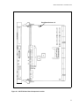
Figure 2-1. MTX Motherboard Component Locations. . . . . . . . . . . . . . . . . . . . . . .
Figure 2-2. Cache Mode Control (J15) . . . . . . . . . . . . . . . . . . . . . . . . . . . . . . . . . .
Figure 2-3. Flash Bank Selection (J37) . . . . . . . . . . . . . . . . . . . . . . . . . . . . . . . . . .
Figure 2-4. Hardware/Firmware Disable of SCSI (J36) . . . . . . . . . . . . . . . . . . . . .
Figure 2-5. DIMM Placement on MTX . . . . . . . . . . . . . . . . . . . . . . . . . . . . . . . . . .
Figure 2-6. PCI Adapter Card Placement on MTX . . . . . . . . . . . . . . . . . . . . . . . . .
Figure 2-7. PMC Module Placement on MTX . . . . . . . . . . . . . . . . . . . . . . . . . . . .
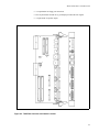
Figure 3-1. 12-Slot Chassis Backplane . . . . . . . . . . . . . . . . . . . . . . . . . . . . . . . . . . .
Figure 3-2. MVME2604 Component Locations . . . . . . . . . . . . . . . . . . . . . . . . . . . .
Figure 3-3. VMEbus System Controller Selection (J22) . . . . . . . . . . . . . . . . . . . . .
Figure 3-4. MVME2604 Flash Bank Selector (J10) . . . . . . . . . . . . . . . . . . . . . . . .
Figure 3-5. MVME4604 Component Locations . . . . . . . . . . . . . . . . . . . . . . . . . . . .
Figure 3-6. VMEbus System Controller Selection (J5) . . . . . . . . . . . . . . . . . . . . . .
Figure 3-7. MVME4604 Flash Bank Selector (J2) . . . . . . . . . . . . . . . . . . . . . . . . .
Figure 3-8. MVME761 Transition Module Connector and Header Placement . . . .
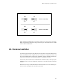
Figure 3-9. Headers J2 and J3 Jumper Settings . . . . . . . . . . . . . . . . . . . . . . . . . . . .
Figure 3-10. MVME761 Three-Row P2 Adapter Component Placement . . . . . . . .
Figure 3-11. MVME761 Five-Row P2 Adapter Component Placement . . . . . . . . .
Figure 4-1. MCP750 Base Board Component Location . . . . . . . . . . . . . . . . . . . . . .
Figure 4-2. Flash Bank Selection (J6) . . . . . . . . . . . . . . . . . . . . . . . . . . . . . . . . . . .
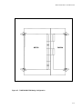
Figure 4-3. TMCP700 Connector and Header Location. . . . . . . . . . . . . . . . . . . . . .
Figure 4-4. Compact FLASH Placement on MCP750 Base Board . . . . . . . . . . . . .
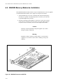
Figure 4-5. RAM300 Placement on MCP750. . . . . . . . . . . . . . . . . . . . . . . . . . . . . .
Figure 4-6. PMC Carrier Board Placement on MCP750 . . . . . . . . . . . . . . . . . . . . .
Figure 4-7. TCMP700/MCP750 Mating Configuration . . . . . . . . . . . . . . . . . . . . . .
Figure 5-1. Command Packet Status Word . . . . . . . . . . . . . . . . . . . . . . . . . . . . . . .
Figure 6-1. Command Packet Status Word . . . . . . . . . . . . . . . . . . . . . . . . . . . . . . .
1-2
1-3
1-4
1-21
2-3
2-4
2-5
2-5
2-7
2-9
2-11
3-3
3-5
3-6
3-7
3-8
3-9
3-10
3-11
3-12
3-13
3-14
4-3
4-4
4-5
4-8
4-10
4-12
4-15
5-26
6-57
Table 2-1. Front Panel Function Header . . . . . . . . . . . . . . . . . . . . . . . . . . . . . . . . . .
Table 2-2. Keyboard/Mouse Conn. Pin Assign’mt . . . . . . . . . . . . . . . . . . . . . . . . . .
Table 2-3. 10/100BaseT Conn. Pin Assign’mt . . . . . . . . . . . . . . . . . . . . . . . . . . . . .
2-13
2-13
2-14
Tables
xii
Contents
Table 2-4. AUI Conn. Pin Assign’mt . . . . . . . . . . . . . . . . . . . . . . . . . . . . . . . . . . . .
Table 2-5. Serial Ports 1/2 Pin Assign’mts . . . . . . . . . . . . . . . . . . . . . . . . . . . . . . . .
Table 2-6. Power Conn. Pin Assign’mts. . . . . . . . . . . . . . . . . . . . . . . . . . . . . . . . . .
Table 3-1. 12-Slot Chassis Backplane Headers . . . . . . . . . . . . . . . . . . . . . . . . . . . .
Table 3-2. Serial Ports 3 and 4 Configuration . . . . . . . . . . . . . . . . . . . . . . . . . . . . .
Table 3-3. VMEbus Connector P2 . . . . . . . . . . . . . . . . . . . . . . . . . . . . . . . . . . . . . .
Table 3-4. Serial Connections - Ports 1 and 2. . . . . . . . . . . . . . . . . . . . . . . . . . . . . .
Table 3-5. Serial Connections - Ports 3 and 4. . . . . . . . . . . . . . . . . . . . . . . . . . . . . .
Table 3-6. Parallel I/O Connector . . . . . . . . . . . . . . . . . . . . . . . . . . . . . . . . . . . . . . .
Table 3-7. Ethernet 10/100Base-T Connector . . . . . . . . . . . . . . . . . . . . . . . . . . . . .
Table 3-8. 8-Bit SCSI Connector . . . . . . . . . . . . . . . . . . . . . . . . . . . . . . . . . . . . . . .
Table 3-9. 16-Bit SCSI Connector . . . . . . . . . . . . . . . . . . . . . . . . . . . . . . . . . . . . . .
Table 3-10. PMC I/O Connector. . . . . . . . . . . . . . . . . . . . . . . . . . . . . . . . . . . . . . . .
Table 5-2. Controller-Independent Error Codes . . . . . . . . . . . . . . . . . . . . . . . . . . . .
Table 5-3. Controller-Dependent Error Codes . . . . . . . . . . . . . . . . . . . . . . . . . . . . .
Table 6-1. ENV Settings (VMEbus Slave Image 0) . . . . . . . . . . . . . . . . . . . . . . . . .
Table 6-2. DRAM Window Sizes . . . . . . . . . . . . . . . . . . . . . . . . . . . . . . . . . . . . . . .
Table 6-3. 256MB MAX DRAM Window - ENV Settings/VMEbus Slave Image 1
Table 6-4. 128MB MAX DRAM Window - ENV Settings/VMEbus Slave Image 1
Table 6-5. 64MB MAX DRAM Window - ENV Settings/VMEbus Slave Image 1
Table 6-6. 1024MB MAX DRAM Window - VMEbus Slave Image 1
Initialization (PH640 Only) . . . . . . . . . . . . . . . . . . . . . . . . . . . . . . . . . . . . . . . . . . . .
Table 6-7. 512MB MAX DRAM Window - VMEbus Slave Image 1
Initialization (PH640 Only) . . . . . . . . . . . . . . . . . . . . . . . . . . . . . . . . . . . . . . . . . . . .
Table 6-9. Controller-Independent Error Codes . . . . . . . . . . . . . . . . . . . . . . . . . . . .
Table 6-10. Controller-Dependent Error Codes . . . . . . . . . . . . . . . . . . . . . . . . . . . .
Table 8-1. Default Processor/PCI/VME Configuration . . . . . . . . . . . . . . . . . . . . . .
Table 8-2. Large 512MB VME Space Example Configuration . . . . . . . . . . . . . . . .
Table 8-3. Using All Available VME Mapping Space . . . . . . . . . . . . . . . . . . . . . . .
2-14
2-15
2-15
3-3
3-12
3-16
3-17
3-17
3-18
3-19
3-19
3-20
3-22
5-27
5-27
6-10
6-11
6-13
6-14
6-15
6-17
6-17
6-57
6-57
8-2
8-7
8-8
xiii
Power Hawk Series 600 Diskless Systems Administrator’s Guide
xiv
Chapter 1
Introduction
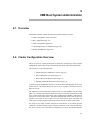
1.1. Overview. . . . . . . . . . . . . . . . . . . . . . . . . . . . . . . . . . . . . . . . . . . . . . . . . . . . . .
1.1.1. Diskless Topography . . . . . . . . . . . . . . . . . . . . . . . . . . . . . . . . . . . . .
1.1.2. Diskless Boot Basics . . . . . . . . . . . . . . . . . . . . . . . . . . . . . . . . . . . . .
1.1.3. Configuration Toolsets . . . . . . . . . . . . . . . . . . . . . . . . . . . . . . . . . . . .
1.2. Definitions . . . . . . . . . . . . . . . . . . . . . . . . . . . . . . . . . . . . . . . . . . . . . . . . . . . .
1.3. Hardware Overview . . . . . . . . . . . . . . . . . . . . . . . . . . . . . . . . . . . . . . . . . . . . .
1.3.1. MTX SBC Features . . . . . . . . . . . . . . . . . . . . . . . . . . . . . . . . . . . . . .
1.3.2. MTX II (MTX604-070) SBC Features. . . . . . . . . . . . . . . . . . . . . . . .
1.3.3. VME SBC Features . . . . . . . . . . . . . . . . . . . . . . . . . . . . . . . . . . . . . .
1.3.4. MCP750 SBC Features . . . . . . . . . . . . . . . . . . . . . . . . . . . . . . . . . . .
1.4. Diskless Implementation . . . . . . . . . . . . . . . . . . . . . . . . . . . . . . . . . . . . . . . . .
1.4.1. Virtual Root . . . . . . . . . . . . . . . . . . . . . . . . . . . . . . . . . . . . . . . . . . . .
1.4.2. Boot Image Creation and Characteristics . . . . . . . . . . . . . . . . . . . . . .
1.4.3. MEMFS Root Filesystem . . . . . . . . . . . . . . . . . . . . . . . . . . . . . . . . . .
1.4.4. Booting . . . . . . . . . . . . . . . . . . . . . . . . . . . . . . . . . . . . . . . . . . . . . . . .
1.4.4.1 VME Boot . . . . . . . . . . . . . . . . . . . . . . . . . . . . . . . . . . . . . . .
1.4.4.2 VME Booting in Remote Clusters . . . . . . . . . . . . . . . . . . . .
1.4.4.3 Net Boot . . . . . . . . . . . . . . . . . . . . . . . . . . . . . . . . . . . . . . . .
1.4.4.4 Flash Boot . . . . . . . . . . . . . . . . . . . . . . . . . . . . . . . . . . . . . . .
1.4.5. VME Networking . . . . . . . . . . . . . . . . . . . . . . . . . . . . . . . . . . . . . . . .
1.4.6. Remote File Sharing . . . . . . . . . . . . . . . . . . . . . . . . . . . . . . . . . . . . . .
1.4.7. Shared Memory . . . . . . . . . . . . . . . . . . . . . . . . . . . . . . . . . . . . . . . . .
1.4.8. Swap Space. . . . . . . . . . . . . . . . . . . . . . . . . . . . . . . . . . . . . . . . . . . . .
1.5. Configuring Diskless Systems . . . . . . . . . . . . . . . . . . . . . . . . . . . . . . . . . . . . .
1.5.1. Closely-Coupled System Hardware Prerequisites . . . . . . . . . . . . . . .
1.5.2. Loosely-Coupled System Hardware Prerequisites . . . . . . . . . . . . . . .
1.5.3. Disk Space Requirements. . . . . . . . . . . . . . . . . . . . . . . . . . . . . . . . . .
1.5.4. Software Prerequisites . . . . . . . . . . . . . . . . . . . . . . . . . . . . . . . . . . . .
1.6. Installation Guidelines . . . . . . . . . . . . . . . . . . . . . . . . . . . . . . . . . . . . . . . . . . .
1.7. Licensing Information . . . . . . . . . . . . . . . . . . . . . . . . . . . . . . . . . . . . . . . . . . .
1-1
1-1
1-4
1-6
1-7
1-10
1-11
1-11
1-12
1-13
1-14
1-14
1-14
1-15
1-16
1-16
1-17
1-17
1-18
1-19
1-21
1-25
1-25
1-27
1-27
1-28
1-28
1-29
1-29
1-30
Power Hawk Series 600 Diskless Systems Administrator’s Guide
1
Chapter 1Introduction
1
1
1
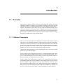
1.1. Overview
This manual is a guide to diskless operation of PowerMAX OS. Diskless operation
encompasses the ability to configure, boot, administer and debug systems that do not have
attached system disks. It should be noted that such a system might have attached non-system disks. Each diskless system runs its own copy of the PowerMAX operating system.
The Closely-Coupled Programming Guide is a companion to this manual and contains
information on the programming interfaces for inter-process communication between
processes that are resident on separate single board computers (SBCs) in diskless configurations where all SBCs share a single VME backplane.
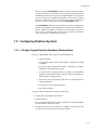
1.1.1. Diskless Topography
There are two basic topographies for configuring a set of single board computers for diskless operation. The topography defines the way that the fileserver, bootserver and diskless
client SBCs are connected. The fileserver is an SBC which has attached a system disk that
stores the boot images that define the software that is downloaded and runs on a diskless
system. The bootserver is an SBC which issues the commands which initiate the boot
sequence. The fileserver also serves as the bootserver of the local cluster.
The two basic diskless topologies, Loosely-Coupled Systems (LCS) and Closely-Coupled
Systems (CCS), are described below:
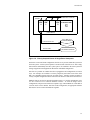
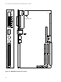
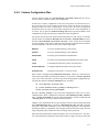
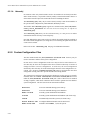
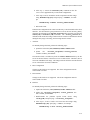
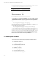
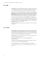
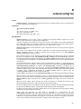
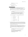
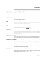
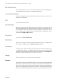
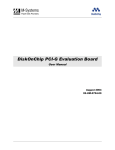
Loosely-Coupled - This configuration (see Figure 1-1) is supported when the only attachment between the fileserver and the diskless system is from an ethernet network. Interprocess communication between processes running on separate single board computers is
limited to standard networking protocols across ethernet.
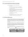
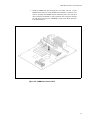
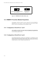
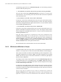
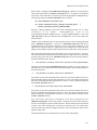
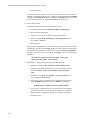
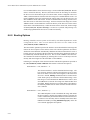
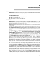
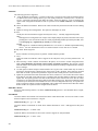
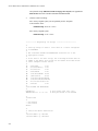
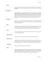
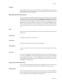
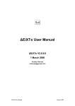
Closely-Coupled - This configuration (see Figure 1-2) is supported when the fileserver
and the diskless SBC share the same VMEbus. Often multiple diskless clients will be in
this same VMEbus. This configuration makes use of the VMEbus to emulate the system
bus of a symmetric multiprocessing system. Many forms of inter-process communication
between processes that are running on separate single board computers are provided. See
the Closely-Coupled Programming Guide for detailed information on these interfaces.
1-1
Power Hawk Series 600 Diskless Systems Administrator’s Guide
FILE SERVER (HOST)
SBC
E
T
H
E
R
N
E
T
FAST/WIDE SCSI-2
RS-232 PORT
SYSTEM DISK
SYSTEM CONSOLE
SBC
SBC
SBC
1
2
N
NETBOOT CLIENTS
Figure 1-1. Loosely-Coupled System Configuration
There are two possible ways of configuring a diskless client system. The difference
between these client configurations is whether the client system maintains an NFS connection to the fileserver after boot such that file system space is available for the client system
on the file server. It is important to note that the type of client system configuration
selected will impact the resource requirements of the file server as will be explained in
more detail later.
The two client configurations are:
Embedded client - Embedded clients are either stand-alone systems which have no attachments to other SBCs or they are not configured with networking and therefore do not use
existing network attachments once the system is up and running. The embedded applications must be a part of the original boot image which is downloaded onto the client system
and those applications begin execution at the end of the boot sequence.
1-2
Introduction
FILE SERVER
(HOST)
DISKLESS CLIENTS
SBC SBC
0
1
SBC
N
OTHER BOARDS
A/D
D/A
1553
(CLUSTER 0)
VME CHASSIS
FAST/WIDE SCSI-2
RS-232 PORT
SYSTEM DISK
SYSTEM CONSOLE
Figure 1-2. Closely-Coupled Cluster of Single Board Computers
NFS client - In an NFS client configuration, the file server provides UNIX file systems for
the client system. A client system operates as an NFS client of the file server. This configuration allows substantially more file system space to be available to the client system for
storing an application and application data than an embedded configuration.
Note that it is possible to combine the above topographies and configurations in various
ways. For example, one could have a Closely-Coupled system where some of the client
SBCs are embedded clients and some are NFS clients. Another example would be a
Closely-Coupled configuration that is booted from an ethernet connection to the fileserver.
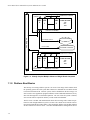
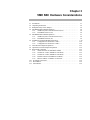
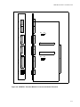
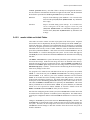
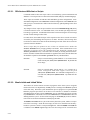
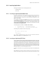
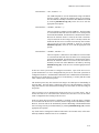
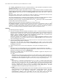
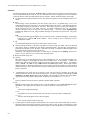
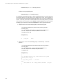
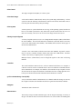
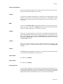
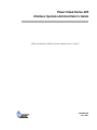
Multiple clusters can also be networked together (Figure 1-3). In this configuration, clusters are connected via a common Ethernet network. As with the single cluster
configuration, each processor board runs a separate copy of PowerMAX OS. Each SBC in
a remote cluster can be diskless. Note that in this configuration, an appropriate ethernet
hub must be used to connect the hardware together.
1-3
Power Hawk Series 600 Diskless Systems Administrator’s Guide
FILE SERVER
(HOST)
DISKLESS CLIENTS
SBC SBC
0
1
SBC
N
OTHER BOARDS
A/D
D/A
1553
(LOCAL CLUSTER)
VME CHASSIS
E
T
H
E
R
N
E
T
SYSTEM DISK
FAST/WIDE SCSI-2
RS-232 PORT
SYSTEM CONSOLE
DISKLESS CLIENTS
SBC SBC
0
1
BOOTSERVER
SBC
N
OTHER BOARDS
A/D
D/A
1553
(REMOTE CLUSTER)
VME CHASSIS
Figure 1-3. Closely-Coupled Multiple Clusters of Single Board Computers
1.1.2. Diskless Boot Basics
The first step in creating a diskless system is to create a boot image which contains both
the operating system and a file system that contains at a minimum the executable needed
to boot the PowerMAX OS. This file system, which is bundled into the boot image, can
also be used to store application programs and data, UNIX commands and libraries or any
other file that might live in a disk-based partition. The size of this file system is limited,
since it must either be copied into memory or must reside in flash ROM.
The file server is an SBC with attached disks where the boot image and a virtual root partition for each configured diskless system is created. The virtual root is both the environment used to build the boot image and it is also mounted by diskless systems that maintain
an NFS connection to the file server. Note that embedded diskless configurations do not
1-4
Introduction
maintain such an NFS connection. When the virtual root is mounted by the diskless system, it is used to hold system commands and utilities as well as user-defined files and
application programs. The virtual root can be viewed as a resource for additional disk
space for a diskless system.
Once a boot image is created, it must be copied from the file server to the diskless system.
There are three supported mechanisms for transferring a boot image to a diskless system:
1. A diskless system that is configured to boot from the network will read the
boot image via an ethernet network connection to the file server. The firmware uses the Trivial File Transfer Protocol (TFTP) over an ethernet connection to download the boot image.
2. When the diskless system shares the same VMEbus with the boot server,
the boot server can transfer the boot image from the file server, across the
VMEbus, directly into the memory of the diskless system.
3. The boot image may have already been burned into flash ROM. In this
case, the board’s firmware (PPCBug) is configured to copy the boot image
from flash ROM into memory.
Closely related to the technique for copying a boot image to a diskless SBC, is the technique for initiating the boot sequence on the diskless SBC. There are four techniques for
initiating the boot sequence on a diskless system. Note that in some cases, the loading of
the boot image cannot be separated from the initiation of execution within that image.
1. To boot from the ethernet network, the board’s firmware (PPCBug) must
be configured to boot from the network. The boot sequence is initiated
either by resetting the board, cycling the power on the board or issuing the
PPCBug command to boot. Note that the PPCBug method is only available when a console terminal is connected to the diskless system.
2. To boot over the VMEbus, the boot sequence is initiated by executing the
sbcboot command on the boot server (which may or may not be the same
system as the file server). This command causes the diskless system to be
reset, the boot image downloaded over the VMEbus into the diskless
system’s memory and execution within the downloaded boot image is initiated.
3. To boot from flash ROM, the board’s firmware (PPCBug) must be configured to boot from flash. The boot sequence will be initiated whenever the
board is reset, cycling the power on the board or issuing the PPCBug command to boot.
4. If a diskless system with a flash ROM boot image shares the VMEbus with
the boot server, then the sbcboot command can be executed on the boot
server to initiate the boot process. Note that in this case, the bootserver can
initiate the boot sequence because the client’s memory and command registers are accessible via the VMEbus.
1-5
Power Hawk Series 600 Diskless Systems Administrator’s Guide
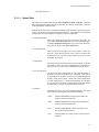
1.1.3. Configuration Toolsets
Two sets of tools are provided for creating the diskless configuration environment on the
file server and for creating boot images. The diskless configuration environment includes
the generation of the virtual root as well as the creation and modification of relevant system configuration files. The virtual root serves as the environment for configuring a client’s kernel, building the boot image and as one of the partitions which is NFS mounted by
an NFS client. The tools that comprise both toolsets are executed on the file server. One
toolset is used for configuring closely-coupled systems while the other toolset is used for
configuring loosely-coupled systems.
The closely-coupled toolset consists of the tools vmebootconfig and mkvmebstrap.
The closely-coupled or VME toolset must be used if the single board computers in the
configuration share a VMEbus and that VMEbus is going to be used for any type of interSBC communication. There are instances where clients in a closely-coupled VME configuration may wish to boot from an ethernet connection to the file server or from flash
ROM. The VME toolset provides support for such booting. Because these clients are part
of a VME cluster, the VME toolset must be used to configure them.
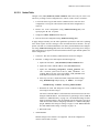
The Net Boot toolset consists of the tools netbootconfig and mknetbstrap. These
tools handle the simpler case of loosely-coupled systems that boot via an ethernet network
or from flash ROM, where no VMEbus-based communication will be utilized on the client
system.
The netbootconfig and vmebootconfig tools are used to create the diskless configuration environment for a diskless client. The mknetbstrap and mkvmebstrap
tools are used for creating a diskless client’s boot image. More information is provided on
these tools in Chapter 5, “Netboot System Administration” and in Chapter 6, “VME Boot
System Administration”.
1-6
Introduction
1.2. Definitions
Loosely-Coupled System
(LCS)
A Loosely-Coupled System (LCS) is a network of Single-Board
Computers (SBCs). One of the SBCs must have a system disk and is
referred to as the File Server and all other SBCs are generally referred
to as clients. An ethernet connection between the file server and the
client systems provides the means for inter-board communication.
Closely-Coupled System
(CCS)
A Closely-Coupled System (CCS) is a set of Single Board Computers
(SBCs) which share the same VMEbus. The first board must have an
attached system disk and acts as the file server for the other boards in
the VMEbus. The VMEbus can be used for various types of interboard communication.
Cluster
A cluster is one or more SBC(s) which reside on the same VMEbus.
In general, a cluster may be viewed as a number of SBCs which
reside in the same VME chassis. Note that “cluster” and “CloselyCoupled system” are synonymous.
Multiple clusters (VME chassis) can be configured together in the
same CCS using Ethernet.
Local Cluster
The cluster which has the File Server as a member (see File Server
below).
Remote Cluster
A cluster which does not have the File Server as a member. In large
configurations, multiple Remote Clusters can be configured. Remote
Clusters rely on an ethernet network connection back to the File
Server for boot loading and NFS mounting of system disk directories.
Board ID (BID)
All SBCs in the same cluster (i.e. reside in the same VME chassis)
are assigned a unique board identifier or BID. The BIDs range from 0
to 21 in any given cluster. Every cluster must define a BID 0.
Additional SBCs installed in a cluster may assign any remaining
unused BID. By convention, BIDs are usually allocated sequentially
[1,2,3] but this is not mandatory.
Host
Generic term used to describe Board ID 0 in any cluster (see
definition of File Server and Boot Server immediately below).
File Server
The File Server has special significance in Loosely-Coupled and
Closely-Coupled systems as it is the only system with physically
attached disk(s) that contain file systems and directories essential to
running the PowerMAX OSTM (/etc, /sbin, /usr, /var, /tmp,
and /dev).
The File Server boots from a locally attached SCSI disk and provides
disk storage space for configuration and system files for all clients.
There is only one file server in a Loosely-coupled or Closely-Coupled
system. The file server must be configured as BID 0 for closely-coupled systems.
All clients depend on the File Server for booting since all the boot
images are stored on the File Server’s disk.
1-7
Power Hawk Series 600 Diskless Systems Administrator’s Guide
Boot Server
The boot server is a special SBC in a Closely-Coupled system,
because it is the SBC that downloads a boot image to all other clients
in the same cluster across the VMEbus. This is known as VME
booting (or VMEbus booting).
The boot server must be configured as board 0 in the cluster in which
it resides (applies to both the local and remote clusters). A boot
server is capable of resetting, downloading, and starting all other
boards in the same cluster (same VMEbus). The VMEbus is utilized
to perform these functions.
In the local cluster, the File Server and the boot server are the same
SBC. In remote clusters, boot server functionality can be provided by
the BID 0 SBC if it is configured as an NFS client.
Client
All SBCs, except for the File Server are considered clients. Clients do
not have their own “system” disk. Clients must rely on the File Server
for such support. However, clients may have local, non-system disk
drives configured.
The two client configurations, embedded and NFS, are described
below:
1) Embedded Client
An embedded client runs self-contained from an internal memorybased file system; they do not offer console or network services.
There is no swap space, because there is no media that can be used for
swapping pages out of main memory. Applications run in single user
mode (init state 1).
2) NFS Client
NFS clients are diskless SBCs that are configured with networking
and NFS. Most directories are NFS mounted from the File Server. In
addition to NFS, all standard PowerMAX OSTM network protocols
are available. Swap space is configured to be remote and is accessed
over NFS. Applications run in multi-user mode (init state 3).
System Disk
The PowerMAX OSTM requires a number of “system” directories to
be available in order for the operating system to function properly.
These directories include: /etc, /sbin, /dev, /usr, /var and
/opt.
The File Server is configured so that these directories are available on
one, or more, locally attached SCSI disk drives.
Since clients do not have locally attached system disk(s), they will
NFS mount these directories from the File Server (an “NFS Client”),
or create them in a memory file system which is loaded with the kernel (an “Embedded Client”).
1-8
VME Boot
A master/slave kernel boot method by which the Boot Server resets,
downloads and starts an operating system kernel on a client which is
attached to the same VMEbus. Note that the client does not initiate
the boot sequence.
Net Boot
(or Network Boot)
A client/server kernel boot method that uses standard BOOTP and
TFTP protocols for kernel loading from the File Server. Any client
can be configured to initiate a net boot operation from the File Server.
Introduction
Flash Boot
A client boot method where the boot image executed comes from the
client’s own Flash memory.
Boot Image
This is the object that is downloaded into the memory of a diskless
client. It contains a UNIX kernel image and a memory-based root file
system. The memory-based file system must contain the utilities and
files needed to boot the kernel. In the case of an NFS client, booting
must proceed to the point that remote file systems can be mounted.
For an embedded kernel, the memory-based file system is the only
file system space that is available on the diskless system. Users may
add their own files to the memory-base file system.
PowerPC Debugger
(PPCBug)
A debugging tool for the Motorola PowerPC microcomputer. Facilities are available for loading, debugging and executing user programs
under complete operator control.
Trivial File Transfer
Protocol(TFTP)
Internet standard protocol for file transfer with minimal capability
and minimal overhead. TFTP depends on the “connectionless” datagram delivery service (UDP).
System Run Level
Init Level
A term used in UNIX-derived systems indicating the level of services
available in the system. Those at “init level 1” are single user systems which in turn is typical of embedded systems running on client
SBCs. Those at “init level 3” have full multi-user, networking, and
NFS features enabled, and is typical of client SBCs that run as netboot clients. See init(1M) for complete details.
VMEbus Networking
In a Closely-Coupled system, all Clients within the same cluster are
transparently networked together using a VMEbus based point-topoint networking driver. This driver provides a high speed TCP/IP
connection between clients which reside on the same VMEbus (i.e.
are in the same cluster).
swap space
Swap reservation space, referred to as ‘virtual swap’ space, is made
up of the number of real memory pages that may be used for user
space translations, plus the amount of secondary storage (disk) swap
space available. Clients in the NFS configuration utilize a file
accessed over NFS as their secondary swap space.
Embedded clients, which are usually also Flashboot clients, generally
do not utilize a swap device, but if a local disk is available then they
too may be configured with a swap device.
1-9
Power Hawk Series 600 Diskless Systems Administrator’s Guide
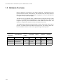
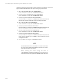
1.3. Hardware Overview
Diskless capabilities are available for four hardware platforms. All platforms have the
requisite network controller, flash memories, and NVRAM which make them suitable as
hosts and as clients in a loosely-coupled diskless topographies. Only the VME platforms
can support a closely-coupled topography.
The MTX is a PC-style platform whose motherboard can be configured as single or dual
processor. The MVME2600 and MVME4600 are single and dual processor single board
computers respectively, whose motherboards are in the VME bus 6u form factor. The
MCP750 is a single board computer in the 6U CompactPCI form factor.
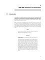
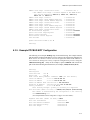
The MVME2600, MVME4600 and MTX boards all utilize the PowerPC 604eTM microprocessor. The MCP750 utilizes the MPC750 microprocessor. The following tables summarize the hardware features of the various supported single board computers.
1-10
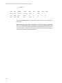
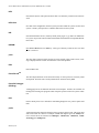
Motherboard
Designation
System Platform
Number
of CPUs
Form Factor
Netboot
VMEboot
Flashboot
MVME2600
Power Hawk 620
1
VME 6U
yes
yes
yes
MVME4600
Power Hawk 640
2
VME 6U
yes
yes
yes
MTX/MTX II
PowerStack II
1 or 2
PC (ATX)
yes
no
yes
MCP750
N/A
1
CPCI 6U
yes
no
yes
Introduction
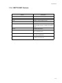
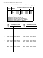
1.3.1. MTX SBC Features
Feature
Description
SBC
PowerPC 604TM -based microprocessor module
DRAM
64 MB to 1 GB EDO ECC Memory
Cache Memory
64 KB L1 cache 256 KB L2 cache
Ethernet
10BaseT or 100BaseT
Flash Memory
1 MB slow flash (Flash B) containing PPCbug
4 MB fast flash (Flash A) available to hold boot
images
SCSI-2
Fast/Wide/Ultra SCSI-2
Ports
Two RS-232 Serial Ports
IEEE-1284 Parallel Port
Real-time Counters/Timers
Two 32-bit counter/timers
Two 16-bit counter/timers
I/O Busses
33 MHz PCI Bus
Fast/Wide/Ultra SCSI Bus
1.3.2. MTX II (MTX604-070) SBC Features
Feature
Description
Microprocessor
Supports BGA 60x processors: 603e, 604c
Single/dual processor (604e); Bus clock
Frequencies up to 66MHz
DRAM
Two-way Interleaved. ECC protected 32 MB to 1
GB on board. Supports single or dual-bank
DIMMS in four on-board connectors.
L2 Cache Memory
Build option for 256 KB or 512 KB Look-aside
L2 Cache (Doubletake).
Flash Memory
8 MB (64-bit wide) plus sockets for 1 MB
(16-bit)
Memory Controller
Falcon3 Chipset
Real-time Clock
8 KB NVRAM with RTC and battery backup.
1-11
Power Hawk Series 600 Diskless Systems Administrator’s Guide
Peripheral Support
Two 16550-compatible async serial ports
One Host-mode Parallel Port
8-bit/16-bit single-ended SCSI Interface
Two 10BaseT/100BaseTX Ethernet Interfaces
One PS/2 Keyboard and one PS/2 Mouse
One PS/2 Floppy Port
PCI Interface
32/64-bit Data, up to 33 MHz operation.
PCI/ISA Expansion
Seven PCI slots (one shared), one ISA slot
(shared)
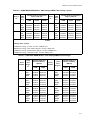
1.3.3. VME SBC Features
Feature
1-12
PH620 (Single Processor)
PH640 (Dual Processor)
SBC
Single PowerPC 604eTM -based
microprocessor module
Dual PowerPC 604TM -based
microprocessor module
DRAM
32 MB to 256 MB ECC Mem- 64 MB to 1 GB ECC Memory
ory
Ethernet
10BaseT or 100BaseT
Flash
1 MB slow flash (Flash B) containing PPCbug
4 MB or 8 MB fast flash (Flash A) available to hold boot images
SCSI-2
Fast and wide (16-bit) SCSI bus
32-bit PCI local bus DMA
Ports
Two asynchronous and two synchronous/asynchronous serial communication ports.
Centronics bidirectional parallel port
Time-of-day
clock (TOC)
8KB x 8 NVRAM and time-of-day clock with replaceable battery
Onboard real-time clocks
(RTCs)
Four 16-bit programmable counter/timers.
Watchdog timer
I/O Busses
A32/D32/BLT64 VMEbus with Master/slave with controller functions.
PMC - slot 32/64-bit
PCI local bus interface
Introduction
1.3.4. MCP750 SBC Features
Feature
Description
SBC
PowerPC 750TM-based microprocessor module
DRAM
64 MB to 1 GB EDO ECC Memory
Cache
64 KB L1 cache 256 KB L2 cache
Ethernet
10BaseT or 100BaseT
Flash
1 MB slow flash (Flash B) containing PPCBug
4 MB fast flash (Flash A) available to hold boot
images
SCSI-2
Fast/Wide/Ultra SCSI-2
Ports
Two RS-232 Serial Ports
IEEE-1284 Parallel Port
Real-time Counters/Timers
Two 32-bit counter/timers
Two 16-bit counter/timers
I/O Busses
33 MHz PCI Bus
Fast/Wide/Ultra SCSI Bus
1-13
Power Hawk Series 600 Diskless Systems Administrator’s Guide
1.4. Diskless Implementation
1.4.1. Virtual Root
The virtual root directory is created on the file server for each client when the client is
configured. The virtual root directory is used to store the kernel build environment, cluster
configuration and device files. In addition, for clients configured with NFS, the client’s
/etc, /var, /tmp and /dev directories are created here and NFS mounted on the
client during system initialization. Note that each configured client has its own, unique
virtual root on the file server which is used as the configuration environment for that
client.
A client’s virtual root directory may be generated in any file system partition on the file
server except for those used for the / (root) and /var file systems.
Virtual roots are created on the host for all clients. Clients running embedded systems will
utilize their virtual root for configuring the clients’s kernel and building the boot image.
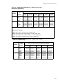
1.4.2. Boot Image Creation and Characteristics
One of the primary functions of the virtual root is as the development environment for
building the boot image that will be downloaded to diskless client systems. After a
client’s virtual root development environment has been created, users have the opportunity
to tune the development environment in various ways, including that of adding in their
own applications and data.
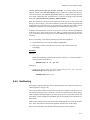
The boot image file, known as unix.bstrap, is composed primarily of two intermediate
files: unix, and memfs.cpio. These are located in the same directory as
unix.bstrap. unix is the client’s kernel as built by idbuild(1M). memfs.cpio
is a compressed cpio archive of all the files which are to be the contents of that client’s
memfs root filesystem. This archive was compressed using the tool rac(1).
Conversely, if the user wants to examine the contents, rac(1) must be used to decompress it.
The final boot image, unix.bstrap, will contain a compressed version of the text and
data regions of the unix kernel. These were extracted from the unix file. It will also contain bootstrap code, which decompresses the kernel and sets up its execution environment
when the boot image is executed on the client, a copy of the compressed cpio image
from memfs.cpio, and a bootstrap record used to communicate information about the
client to the kernel and its bootstrap.
At the time of booting, boot files are created as needed based on dependencies established
by the makefile “bstrap.makefile” under the /usr/etc/diskless/bin directory (see table below).
1-14
Introduction
Boot File
Description
Dependencies
unix
unix kernel
kernel.modlist.add
memfs.cpio
cpio image of all files to be loaded in the
client’s memory-based root file system
unix,
memfs.files.add,
system configuration
files
unix.bstrap
bootstrap image
unix, memfs.cpio
1.4.3. MEMFS Root Filesystem
A memory-based filesystem, called the memfs filesystem, becomes the root filesystem of
a client as part of its booting process. As the client completes its boot, it may mount other
filesystems that are available to it, perhaps those on local disks or from across the network.
These other filesystems do not replace the original memfs root filesystem but instead augment it with their extra directories and files. Files needed by diskless applications can be
located either in the memfs root filesystem of a client or on the file server in the client’s
virtual root directory.
For embedded systems, all user applications and data must be placed into the memfs root
filesystem, since by definition no other filesystems are available to such clients.
The tools used to build boot images provide a mechanism for adding user-defined files to
the memfs filesystem contents and wraps those contents into the boot image that will be
later downloaded into the client. When the boot image is downloaded into a diskless client
system, it is resident in memory whether or not the files are being used. This means that
the number and size of files that can be placed into the memfs file system is thus limited.
This effect is minimized when the boot image is loaded into Flash. When the boot image
resides in Flash, only those files actually in use will reside in (be copied into) physical
memory at any time. In this mode of operation, the root filesystem behaves more like a
normal filesystem: pages are automatically fetched from the Flash as needed, and, if not
modified by applications, are automatically released when other needs for the space
become more urgent.
It is possible for applications running on the client to write to memfs files; however, there
not being a disk associated with these files, the changes will be lost on the next reboot of
that client. Moreover, such pages remain permanently in memory until the files containing
them are deleted or truncated. This ties up precious physical memory. This can be alleviated only by the addition of a swap device to the system, to which the system can write
these dirty pages to as necessary, or by careful consideration and minimization of how
much file writing is done by embedded applications into the memfs root filesystem.
Memfs filesystems stored in Flash will be in a compressed format, in order to make maximum use of this relatively tiny device.
1-15
Power Hawk Series 600 Diskless Systems Administrator’s Guide
1.4.4. Booting
Once a bootstrap image is generated, it must be loaded and started on the client for which
it was built. Three methods of booting are provided: VME Boot, Net Boot and Flash Boot.
All three methods are supported in closely-coupled configurations while only net boot and
flash boot are supported in loosely-coupled configurations. (These methods are explained
in more detail in the following sub-sections.)
In configuring a diskless configuration, the user must decide which method of booting will
be used for each diskless client. Booting of a diskless client consists of two distinct
operations. First, the boot image must be downloaded to the diskless client. Downloading
can be performed over the VMEbus (supported only in closely-coupled configurations) or
across an ethernet network (supported in both closely-coupled and loosely-coupled configurations). Downloading using these two mechanisms differs in that a VME download is
a ‘push’ operation, while an ethernet download is a ‘pull’ operation. That is, the VME
download is initiated by commands that are executed on the file server, which cause the
boot image to be written to the client’s DRAM. An ethernet download is initiated by
PPCBug firmware commands, which are executed on the diskless client and cause the
boot image to be read from the file server and downloaded in the client’s DRAM.
The second phase of the boot operation is to initiate execution within the downloaded
image. Like the download of the boot image, initiation of execution is also be performed
via the VMEbus or via the PPCBug commands executed on the client system. In managing a diskless configuration, the user will generally be unaware of the distinction between
the two phases of the boot process. This is because the command used to boot, using the
VMEbus or the PPCBug commands, executed on the diskless client to boot using ethernet,
actually perform both phases of the boot operation. The distinction between these two
phases of booting is made here to better understand the third boot mechanism: booting
from flash.
The boot image can be burned into flash on the diskless client. Once burned into flash, the
complete image no longer needs to be downloaded into DRAM. Instead, only the
operating system is copied from flash into DRAM, the compressed cpio file system is
left in flash and only copied into memory as needed. This means that booting from flash
doesn’t require phase one of the boot process - the download of the boot image. The
method used to initiate execution within the boot image for a flash boot system depends
upon the connection between the file server and the client. If the diskless client and the
file server are located in the same VMEbus, then a command can be executed on the file
server that will initiate the flash boot sequence on the client. If the client has only a network connection to the file server or has no connection at all to the file server, then the
boot sequence must be initiated using a PPCBug command.
Booting from flash is significantly faster than other boot mechanisms and is recommended
for final deployed environments. While actively testing and modifying the application and
the boot image, downloading the boot image can be performed via the VMEbus or via an
ethernet connection. The final version of the boot image can then be burned into flash
when the application is deployed.
1.4.4.1. VME Boot
In a Closely-Coupled configuration, the boot server (board ID 0 of cluster) is capable of
downloading a boot image to all other clients in the same cluster across the VMEbus.
1-16
Introduction
VME booting (or VMEbus booting) uses the VMEbus to transfer the PowerMAX OSTM
bootstrap image from the File Server’s disk to the client’s DRAM (memory).
A VME boot will result in the hardware reset of the boot client. This stops execution of
any code running on the boot client. It is suggested that when rebooting any client that is
currently running a PowerMAX OSTM bootstrap image, that it be shutdown (e.g. using
shutdown(1M)) prior to rebooting (if possible).
Once the client is reset, the Boot Server’s on-board DMA Controller transfers the
bootstrap image from the File Server’s disk to the client. A command, sent over the
VMEbus to a special memory location on the client, starts execution of the bootstrap
image. VME booting is only available for clients which have a “Boot Server” defined
which resides on the same VMEbus as the boot client. In the local cluster, the File Server
is also the Boot Server for all clients on the local VMEbus.
1.4.4.2. VME Booting in Remote Clusters
A remote cluster is a VME cluster which does not contain the file server. In this case, the
Boot Server is the SBC with Board ID 0. The bootserver must be configured as an NFS
Client to allow it access to the boot images of the VME boot clients for which it will act as
the boot server. If the remote cluster’s Board ID 0 SBC is configured as an Embedded
Client, then VME booting is not an option for any clients in the same remote cluster. In
this case, the Net Booting or Flash Booting method must be used for all clients in the
remote cluster.
The Boot Server in a remote VME Cluster must be booted using the Net Boot method
described below. This is because the Boot Server is not physically connected to the same
VMEbus as the File Server (the SBC which has the Boot Server’s bootstrap image on
disk).
Once the Boot Server is Net booted, all other clients in the same remote cluster can be
VME booted by the cluster’s boot server.
1.4.4.3. Net Boot
Net Boot (or Network booting) is an alternative method of loading and executing a kernel
image to a client over Ethernet. Note that the PPCBug firmware supports booting via
ethernet but not other networking media. This method is distinguished by the fact that the
host cannot actively force a client to accept and boot an image; rather, the client must initiate the transfer with the host and cooperate with the host to complete the transfer. This
client initiation may take one of two forms: PPCBug commands executed on the client
console by an operator, or an automatic execution of the same PPCBug commands by the
client whenever it is powered up, or reset (autoboot).
Net booting is performed by PPCBug using the TFTP (Trivial File Transfer Protocol,
RFC783) and optionally, the BOOTP (Bootstrap Protocol, RFC951) network protocols.
These are standard protocols supported by the PowerMAX OS TM and are explained in
more detail in the Network Administration manual (Pubs No. 0890432).
Any client can be net booted as long as the SBC is physically connected to the same
Ethernet as the File Server.
1-17
Power Hawk Series 600 Diskless Systems Administrator’s Guide
In closely-coupled systems, some clients, namely Boot Servers, must be net booted. Other
SBCs in the same VME chassis as a Boot Server may be, and usually are, booted over the
VMEbus by the Boot Server.
Whether manually booting or autobooting a client, that client must first be set up with the
information it needs to do net booting. This is accomplished with the PPCBug NIOT
command. Once this is done, the client should not ever need to be reconfigured unless one
or more of these parameters change, as the information is saved in NVRAM and thus will
be preserved across reboots and powerdown cycles.
The following information is required by the PPCBug NIOT command to configure each
client you want to perform a net boot:
File Server IP Address
IP address for the File Server which should have already been
defined in the /etc/hosts file. You must use the address which
defines the Ethernet interface, not the VME network interface.
Client(client) IP Address
IP address which PPCBug will use as the return address for TFTP
data transfer. For NFS clients, this is the Ethernet IP Address.
You may also net boot an Embedded Client. Since this client’s
kernel does not support networking, no IP address has yet been
defined for it. In this situation, select a unique IP address to use.
An address should be selected that decodes to the same subnet as
the File Server, and does not conflict with any other IP addresses
used in the network.
Subnet IP Address Mask
Subnet mask used for this interface. It normally is 255.255.255.0.
Broadcast IP Address
Broadcast address used for this subnet.
Absolute Pathname of UNIX Bootstrap to be Downloaded
The bootstrap is a file generated by the configuration utility as
<client_virtual_rootpath>/etc/conf/cf.d
/unix.bstrap.
After the PPCBug firmware has been initialized with the network parameters, a net boot
may be initiated via the PPCBug NBO command. Refer to Chapter 5, Netboot System
Administration, for more information on net booting.
1.4.4.4. Flash Boot
Flash Boot or flash booting, is a method of loading and executing a kernel image from
Flash ROM. Flash booting is the preferred method of booting a diskless client in the production or deployed phase of an application. There are two advantages in booting from
flash. First, flash boot allows very fast boot times because there are no rotational delays
that would normally be associated with reading from disk. Second, the root file system is
maintained as a read-only image in flash, providing much greater system stability because
the root file system cannot be corrupted by unexpected system crashes which might leave
a writable file system in an inconsistent state.
1-18
Introduction
The boot image that is downloaded into flash is the same boot image that can be downloaded via the VME backplane or via an ethernet network connection. Therefore a developer can use one of the other download/boot techniques while actively modifying the boot
image during the development phase, and then use the same final boot image in the flash
when in the deployed phase of the application. There are no tools specifically targeted
towards creating boot images for flash booting. Instead, either the loosely-coupled or
closely-coupled configuration tools are used for building the image, depending on whether
the client system will be used in a shared VME backplane configuration.
The first step in preparing an SBC for flash boot is to load the boot image into flash ROM
on the board. Loading an image into flash ROM may be done via two different processes
depending on whether or not the file server and the diskless client share the same VMEbus.
If the two SBCs do share the same VMEbus, then the boot image can be downloaded into
memory and burned into flash by running the sbcboot utility or via mkvmebstrap.
Once the boot image is burned into Flash, the same utilities can be used to initiate a download of the boot image from Flash to memory and begin execution within the downloaded
boot image.
If the file server is only connected to the client system via an ethernet network, then the
Flash must be burned via a process known as “network loading.” Preparation for loading
the boot image into flash is the same method used above for net booting, that is, using the
PPCBug NIOT command. The PPCBug NBH command is used to load the boot image
into memory without execution of that image. The boot image is then burned into Flash
from memory via the PPCBug PFLASH command. Once the image is burned into Flash,
then all subsequent booting can be done from the image stored in Flash by configuring the
board’s boot device to be the Flash via the PPCBug ENV command. Refer to Chapter 7,
Flash Boot System Administration, for more information.
1.4.5. VME Networking
For closely-coupled configurations, the cluster software package provides the capability of
networking between clients and the file server, utilizing the VME bus for data transfer.
Figure 1-4 illustrates the streams networking model, which includes interface modules to
enable standard networking across the VME bus.
This VME network connection is a point-to-point link and is analogous to a SLIP or PPP
connection. A point-to-point VME bus connection is established via the vmedlpiattach(1M) command. This command is executed at boot time by the file server and clients to establish connections with the other Power Hawk boards.
The netstat(1M) command shows the VME point-to-point connections:
1-19
Power Hawk Series 600 Diskless Systems Administrator’s Guide
netstat -i
Name
Mtu
Network
Address
Ipkts
Ierrs
Opkts
Oerrs
Collis
vme0
8320
192.168.1
elroy_vme
34391
0
34392
0
0
lo1
2048
none
none
10
0
10
4
0
dec0
1500
none
none
12374
0
0
0
0
The interface vme0 represents one VME point-to-point connection with another Power
Hawk board.
When configuring a VME cluster, the IP addresses of the Power Hawk systems on the
VME bus are defined based upon the VME IP Base Address of the cluster, and the appropriate entries must be added to the /etc/hosts file. Required kernel device drivers for
VME networking are configured and applicable VME network related tunable parameters
are initialized to reflect the configured IP address.
1-20
Introduction
NFS
RFS
YP
RPC Services
telnet
ftp
tftp
RPC/XDR
libnsl.so
rlogin
rsh
rcp
libsocket.so
User
Kernel
Interface Modules
TIMOD
SOCKMOD
Protocols
TCP
UDP
RAWIP
ICMP
IP
ARP
APP
Network
Device Drivers
VMEDLPI
Loopback
VMEMSG
DEC
SBC
Ethernet
VME Bus
Figure 1-4. Power Hawk Networking Structure
1.4.6. Remote File Sharing
Clients configured as “Embedded Clients” must have in their memory-based root file
system all the files needed for booting and all the files needed to run applications. This is
because Embedded Clients do not have networking by definition and therefore will not
have access to remote files on the file server.
1-21
Power Hawk Series 600 Diskless Systems Administrator’s Guide
The memfs root file system of a client configured with NFS, need only contain the files
required for booting. When the client system reaches init state 3 it is able to NFS mount
and access the file server’s directories. The NFS mounts are executed from a start-up script
in /etc/rc3.d.
Two different inittab files are used in booting an NFS configuration. When the etc
directory in a client’s virtual root is NFS mounted, the original inittab file is overlaid
with the one in the virtual root. The directory etc/rc3.d is then re-scanned to execute
start-up scripts in the virtual root.
The directories /usr, /sbin and /opt are completely shared with the server, while
/etc and /var are shared on a file-by-file basis.
Listed below is the NFS mount scheme in use:
Path on File Server
Mount Point on Client
/usr
/usr
/sbin
/sbin
/opt
/opt
<virtual_rootpath>/etc
/etc
<virtual_rootpath>/var
/var
<virtual_rootpath>/dev
/dev
<virtual_rootpath>/tmp
/tmp
/etc
/shared/etc
/var
/shared/var
/dev
/shared/dev
The /etc and /var directories under the client’s virtual root contain some files that are
client-specific and therefore these files cannot be shared. These directories also contain
files which have the same content for the file server and all client virtual roots on the file
server, these files are shared. Because the /etc and /var directories contain both shared
and non-shared files, yet all files must reside in this directory (because the standard utilities expect them to be in those directories), these directories require special treatment in
the client’s virtual root.
The files /etc/nodename (not shared) and /etc/chroot (shared) will be used to
illustrate how shared and non-shared files are handled in /etc and /var.
The /etc/nodename file is simply created as a real file in the client’s virtual root under
the <virtual_rootpath>/etc directory. The <virtual_rootpath>/etc directory is mounted on the diskless client under the /etc directory.
The /etc/chroot file is created in the client’s virtual root not as a real file, but as a
symbolic link to the file name /shared/etc/chroot. On the file server there is no
such directory as /shared. On the client system, /shared is used as the mount point
for mounting the file server’s actual /etc/ directory. Thus any reference on the diskless
client to /etc/chroot will actually be referencing the /etc/chroot file that exists in
the file server’s /etc directory.
1-22
Introduction
File Server System
/
(root)
/etc
< virtual_root >
etc
nodename
chroot
/shared/etc/chroot
Client System
/
(root)
/etc (server: < virtual_root >/etc)
/shared
etc (server: /etc)
nodename
chroot
chroot
As new files are added and removed from the file server’s /etc and /var directories, the
symbolic links under the client’s virtual root may become stale. The configuration utilities
mkvmebstrap and mknetbstrap can be used to update the links in these directories
to match the current state of the file server.
The directories /dev and /tmp are also created under the client’s virtual root but do not
share any files with the file server. Device files may have kernel dependencies and so
these files are not shared. The directory /tmp is created as an empty directory.
Once the client system is up and running, the files in the memory-based root file system
required for booting are no longer needed and are removed to free up memory.
Permission to access remote files on the file server is automatically granted. During client
configuration, the dfstab(4) and dfstab.diskless tables are modified to allow a
client either read or read/write access to files which reside on the file server.
1-23
Power Hawk Series 600 Diskless Systems Administrator’s Guide
The dfstab.diskless file is generated when the first client is configured. Sample
entries from this file are listed below. These entries should not be modified.
share
share
share
share
share
share
-F
-F
-F
-F
-F
-F
nfs
nfs
nfs
nfs
nfs
nfs
-o
-o
-o
-o
-o
-o
ro,root=$CLIENTS
ro,root=$CLIENTS
rw=$CLIENTS,root=$CLIENTS
ro,root=$CLIENTS
rw=$CLIENTS,root=$CLIENTS
rw=$CLIENTS,root=$CLIENTS
-d
-d
-d
-d
-d
-d
“/etc/”
“/dev/”
“/var/”
“/sbin/”
“/usr/”
“/opt/”
/etc
/dev
/var
/sbin
/usr
/opt
/shared/etc
/shared/dev
/shared/var
/sbin
/usr
/opt
The dfstab.diskless file is referenced from a command line entry in dfstab,
generated when the first client is configured. For every client configured thereafter, the
client’s name is added to the CLIENTS variable. For example, after configuring two
clients, named t1c1_vme and t2c1_vme, the following line appears in the dfstab
table.
CLIENTS=t2c1_vme:t1c1_vme /usr/sbin/shareall -F \
nfs /etc/dfs/dfstab.diskless
In addition, an entry to make each client’s virtual root directory accessible is generated at
configuration time. If a parent directory of the client’s virtual root directory is already
currently shared (has an entry in sharetab(4)), then the matching entry in
dfstab(4), if found, is modified to include the client in its rw= and root= attribute
specifications. For example, if the virtual root directory for the client named t1c1_vme is
in /home/vroots/t1c1 and the /home/vroots directory is currently shared; then
the sample entry below would be changed as shown below.
from:
/usr/sbin/share -F nfs
-d “/home/vroots” /home/vroots vroots
to:
/usr/sbin/share -F nfs -o root=t1c1_vme -d \
“/home/vroots” /home/vroots vroots
Note that there is no need to add an rw= attribute since, when not specified, it defaults to
read/write access permissions to all.
If no entry is currently shared that covers the client’s virtual root directory, a specific entry
for each client is appended to the dfstab.diskless file. For example, for the client
named t1c1_vme, whose virtual root directory is /home/vroots/t1c1, the following
entry is generated:
/usr/sbin/share -F nfs -o rw=t1c1_vme,root=t1c1_vme -d \
“/home/vroots/t1c1” /home/vroots/t1c1 vroot
After the files are updated, the “shareall -F nfs” command is executed to update the
file server’s shared file system table.
When a client’s configuration is removed, all references to the client and it’s virtual root
directory are removed from both the dfstab and dfstab.diskless files and the
shareall(1M) command is executed to update the shared file system table.
1-24
Introduction
1.4.7. Shared Memory
Closely-Coupled systems can be configured such that SBCs within the same VME cluster
can share memory with each other in two ways. These methods are explained below.
Refer to Chapter 3, Shared Memory and Appendix A both located in the Closely-Coupled
Programmers Guide, for further information.
Slave MMAP
This interface allows mmap(2), shmbind(2), read(2) and write(2) access to a
shared memory area on each SBC configured with Slave MMAP support. In this shared
memory implementation, each SBC with memory to share with other SBCs, maps it’s own
contiguous memory into a predefined VMEbus A32 address range. All memory mapped in
this way is accessible simultaneously by all SBCs in the cluster.
Master MMAP (formerly called Master MMAP Type 2)
This interface allows mmap(2) and shmbind(2) access to any single contiguous VMEbus A32 address range, with the exception of the VMEbus A32 space used to map the
local SBC’s DRAM and the address range occupied by the Slave MMAP interface
described above (i.e. you cannot access your own DRAM through this interface). The
amount of external VMEbus address space that can be mapped is dependent on the amount
of unassigned PCI memory space in the configured system. In some systems, 512MB (or
more) of VMEbus A32 address space could be mapped in this manner. Only one Master
MMAP interface can be defined on a given SBC.
1.4.8. Swap Space
Embedded systems generally do not have swap space. Nevertheless, some aspects of
swap space configuration do affect even embedded systems, so this section should be read
even for these users. In particular, every client system, NFS or embedded, should have
the kernel tunable DISSWAPRES enabled. The meaning and consequences of this
tunable are described later in this section.
Normal systems have a disk partition reserved for swap space. For diskless nfs clients,
swap space is implemented using a regular file created in the client’s virtual root directory
and accessed over NFS. The size of the swap file is user-configurable.
Swap reservation space, referred to as ‘virtual swap’ space, is made up of the number of
real memory pages that may be used for user space translations, plus the amount of
secondary storage (disk) swap space available. Note that if no secondary storage swap
space is available, then the amount of virtual swap space degenerates to the number of real
memory pages available for user address space.
A virtual swap space reservation is made by decrementing the amount of available virtual
swap space. If no virtual swap space is available, then the reservation will fail, and
subsequently, either the page fault or segment create operation will not succeed. Virtual
swap reservations are made so that as real memory becomes low, the pageout and process
swap daemons can guarantee that there will be an appropriate number of user pages that
can be swapped out to secondary storage and subsequently freed, in order to maintain an
adequate level of free memory pages for new page allocations.
1-25
Power Hawk Series 600 Diskless Systems Administrator’s Guide
Even when there is no swap space configured into the kernel, the virtual swap reservations
will prevent the kernel from overcommitting real memory to user pages that cannot be
swapped and freed if and when the number of free real memory pages becomes low. If
these daemons did not maintain an adequate number of free memory pages for page
allocations, then applications might become blocked forever in the kernel, waiting for their
page allocation requests (or internal kernel memory page allocation requests) to complete.
There are a number of possible swap space configurations on client systems:
1. no swap space
typically, this would be a client configured in Embedded
mode
2. remote swap space
client would be configured as a NFS diskless system with
the swap space accessed through the NFS subsystem
3. local disk swap space
client configured in either NFS or Embedded mode, client
configured to use a local disk for swap space
When there is no swap space, or a small amount of swap space, it may be necessary to
modify the default values of certain system tunables in order to maximize system
performance and user virtual space capacities.
The following are some of the system tunables that are relevant to system swap space
management in a system with little or no secondary storage swap space.
1. Systems with no swap space should be tuned such that process swapping
does not become aggressively active before process growth is limited by
virtual swap reservations, as this will impact system performance without
providing significant amounts of additional free memory. The address
space aging interval should also be increased.
System tunables that govern the address space aging interval are:
INIT_AGEQUANTUM
MIN_AGEQUANTUM
MAX_AGEQUANTUM
LO_GROW_RATE
HI_GROW_RATE
In order to ensure longer address space aging intervals, all of these tunables
may be set to a higher than default value.
2. The GPGSLO tunable value can be decreased in order to lower the free
memory level at which process swapping will become aggressively active.
3. The DISSWAPRES tunable disables virtual swap reservations by setting the
amount of available virtual swap space to an artificially large value.
The DISSWAPRES tunable allows more user page identities/objects to be
created than what can be accommodated for in virtual swap space. Since
typically, applications do not tend to access all the pages that may
potentially be considered writable (and therefore require a virtual swap
reservation), this tunable may allow for a larger number of applications to
run simultaneously on a system by not requiring virtual swap space for
every potentially writable user page.
1-26
Introduction
However, when the DISSWAPRES tunable is enabled, it becomes possible
for page allocations to block forever, since the pageout and process swap
daemons may not be able to swap out an adequate number of user pages in
order to free up pages for additional allocations. At this point, the system
will enter a state where little or no useful work is being accomplished.
Therefore, caution is advised when using the DISSWAPRES tunable.
The DISSWAPRES tunable may be useful when a fixed set of applications
and their corresponding virtual address space working sets are known to fit
into the amount of available real memory (and secondary storage swap
space, if any), even though their total virtual swap space requirements
exceed the system’s virtual swap space capacity.
1.5. Configuring Diskless Systems
1.5.1. Closely-Coupled System Hardware Prerequisites
A Closely-Coupled VME cluster requires the following hardware:
• VME card chassis
• One host Power Hawk single board computer: (minimum of 32 MB
of DRAM)
• One Power Hawk single board computer: (minimum of 32 MB of
DRAM) for each desired client system.
• A minimum of one transition module. Note that a second transition
module is recommended so that a console terminal can be attached to
diskless SBCs for debug purposes.
• One SCSI 2 GB (4 GB preferred) disk drive for PowerMAX OSTM
software installation
• SCSI tape drive for software installation
• One console terminal
A Closely-Coupled remote cluster requires the following:
• a remote file server single board computer
• VME card chassis
• One Power Hawk single-board computer (minimum of 32 MB of DRAM)
for each desired remote client system.
• An appropriate Ethernet interconnect (for example, multiport hub) with
cabling to connect local cluster and all remote clusters
1-27
Power Hawk Series 600 Diskless Systems Administrator’s Guide
1.5.2. Loosely-Coupled System Hardware Prerequisites
A loosely-coupled configuration requires the following hardware:
• a card chassis
• One host single board computer: (minimum of 32 MB of DRAM)
• One single board computer: (minimum of 32 MB of DRAM) for
each desired client system.
• A minimum of one transition module. Note that a second transition
module is recommended so that a console terminal can be attached to
diskless SBCs for debug purposes.
• One SCSI 2 GB (4 GB preferred) disk drive for PowerMAX OSTM
software installation
• SCSI tape drive for software installation
• One console terminal
• An appropriate Ethernet interconnect (for example, multiport hub)
with cabling to connect local cluster and all remote clusters
1.5.3. Disk Space Requirements
The table below details the amount of available disk space required per client single board
computer for the virtual root partition. These values are for the default shipped configuration. Added applications may increase disk space requirements. Values in this table do not
include swap space for the diskless system. The amount of swap space is configurable,
but should be at least one and one-half times the size of physical memory on the single
board computer.
Also note that the boot images of remote clients configured to vmeboot are stored in the
virtual root directory of the bootserver of the cluster. Therefore, clients serving as bootservers of remote clusters require more disk space in their virtual root partitions. The
additional disk space can be calculated as the number of clients in the remote cluster configured to vmeboot multiplied times the boot image size. The default compressed boot
image is approximately 3.5 megabytes.
A client’s virtual root directory can be generated in any disk partition on the file server.
The /(root) and /var file systems are not recommended for use as client virtual
partitions..
Client Configuration
1-28
Disk Space
NFS
25 Megabytes
Embedded
15 Megabytes
Introduction
1.5.4. Software Prerequisites
The following software packages must be installed on the host system prior to installing
the cluster package (prerequisite packages listed alphabetically by package name):
Package Dependencies (See note)
Package Name
Package Description
base
Base System (Release 4.3 or later)
cmds
Advanced Commands
lp, nsu
dec
DEC Ethernet Driver
nsu
dfs
Distributed File System Utilities
inet
inet
Internet Utilities
nsu
lp
Printer Support
ncr
Internal NCR SCSI Driver
netcmds
Commands Networking Extension
lp, inet
nfs
Network File System Utilities
nsu, inet, rpc, dfs
nsu
Network Support Utilities
rpc
Remote Procedure Call Utilities
inet
Note: All packages are dependent on base package
1.6. Installation Guidelines
The following instructions assume that all the prerequisite hardware has been installed.
For details, see “Hardware Prerequisites” and depending on your SBC board
type, refer to one of the following chapters:
-
Chapter 2, MTX SBC Hardware Considerations
Chapter 3, VME SBC Hardware Considerations
Chapter 4, MCP750 Hardware Considerations
1-29
Power Hawk Series 600 Diskless Systems Administrator’s Guide
1.7. Licensing Information
The system installed on the file server carries a license for the number of processors
allowed to be booted. The license also carries a limit for the number of users allowed to
log on to the file server. All diskless client SBCs are limited to a maximum of 2 users each.
To print the processor and user limits set for your machine, use the -g option of the
keyadm(1M) command.
1-30
Chapter 2
MTX SBC Hardware Considerations
2.1.
2.2.
2.3.
2.4.
Introduction . . . . . . . . . . . . . . . . . . . . . . . . . . . . . . . . . . . . . . . . . . . . . . . . . . . .
Unpacking Instructions . . . . . . . . . . . . . . . . . . . . . . . . . . . . . . . . . . . . . . . . . . .
Hardware Configuration . . . . . . . . . . . . . . . . . . . . . . . . . . . . . . . . . . . . . . . . . .
MTX Motherboard Preparation . . . . . . . . . . . . . . . . . . . . . . . . . . . . . . . . . . . . .
2.4.1. Cache Mode Control (J15) . . . . . . . . . . . . . . . . . . . . . . . . . . . . . . . . . .
2.5. Flash Bank Selection (J37) . . . . . . . . . . . . . . . . . . . . . . . . . . . . . . . . . . . . . . . .
2.5.1. Power Control for ATX Power Supply (J27) . . . . . . . . . . . . . . . . . . . .
2.5.2. Hardware/Firmware Disable of SCSI (J36) . . . . . . . . . . . . . . . . . . . . .
2.5.3. Remote Status and Control. . . . . . . . . . . . . . . . . . . . . . . . . . . . . . . . . .
2.6. Hardware Installation. . . . . . . . . . . . . . . . . . . . . . . . . . . . . . . . . . . . . . . . . . . . .
2.7. DIMM Memory Installation . . . . . . . . . . . . . . . . . . . . . . . . . . . . . . . . . . . . . . .
2.8. PCI Adapter Installation . . . . . . . . . . . . . . . . . . . . . . . . . . . . . . . . . . . . . . . . . .
2.9. PMC Module Installation . . . . . . . . . . . . . . . . . . . . . . . . . . . . . . . . . . . . . . . . .
2.10. MTX Motherboard Installation . . . . . . . . . . . . . . . . . . . . . . . . . . . . . . . . . . . .
2.10.1. MTX Motherboard . . . . . . . . . . . . . . . . . . . . . . . . . . . . . . . . . . . . . . .
2.11. MTX Series Connectors . . . . . . . . . . . . . . . . . . . . . . . . . . . . . . . . . . . . . . . . .
2.11.1. Front Panel Function Header . . . . . . . . . . . . . . . . . . . . . . . . . . . . . . .
2.11.2. Rear Panel Keyboard/Mouse Connectors. . . . . . . . . . . . . . . . . . . . . .
2.11.3. 10BaseT/100BaseT Connector. . . . . . . . . . . . . . . . . . . . . . . . . . . . . .
2.11.4. AUI Connector . . . . . . . . . . . . . . . . . . . . . . . . . . . . . . . . . . . . . . . . . .
2.11.5. Serial Ports 1 and 2 Connectors . . . . . . . . . . . . . . . . . . . . . . . . . . . . .
2.11.6. Power Connector . . . . . . . . . . . . . . . . . . . . . . . . . . . . . . . . . . . . . . . .
2.12. Reset Button . . . . . . . . . . . . . . . . . . . . . . . . . . . . . . . . . . . . . . . . . . . . . . . . . .
2-1
2-2
2-2
2-2
2-4
2-4
2-5
2-5
2-6
2-6
2-6
2-8
2-9
2-11
2-12
2-13
2-13
2-13
2-14
2-14
2-15
2-15
2-16
Power Hawk Series 600 Diskless Systems Administrator’s Guide
2
Chapter 2MTX SBC Hardware Considerations
2
2
2
2.1. Introduction
This chapter provides hardware preparation, installation instructions and general operating
information. The MTX Single Board Computers (SBCs) including optional PMC or PCI
adapter boards, can be packaged in various chassis configurations depending on end-user
application requirements.
Refer to the applicable Motorola MTX Series Installation and Use Manual for more
detailed information on hardware considerations that may be applicable to your particular
hardware configuration. Refer to the Preface of this manual for specific manual titles,
document numbers, and Motorola’s web site address to access documents online.
NOTE
MTX boards come with a variety of minor differences. Unless
otherwise stated, all the information provided in this chapter is
generally applicable to all variations of MTX boards. However,
please reference the applicable online documents for a complete
description of the MTX604-070 family of motherboards (sometimes referred to as “MTX II” in this manual).
CAUTION
Avoid touching areas of integrated circuitry; static discharge can
damage circuits.
Concurrent strongly recommends that you use an antistatic wrist
strap and a conductive foam pad when installing or upgrading a
system. Electronic components, such as disk drive, computer
boards, and memory modules, can be extremely sensitive to
Electrostatic Discharge (ESD). After removing the component
from the system or its protective wrapper, place the component
flat on a grounded, static-free surface (and in the case of a board,
component side up). Do not slide the component over any surface.
If an ESD station is not available, you can avoid damage resulting
from ESD by wearing an antistatic strap (available at electronic
stores) that is attached to an unpainted metal part of the system
chassis.
2-1
Power Hawk Series 600 Diskless Systems Administrator’s Guide
2.2. Unpacking Instructions
NOTE
If the shipping container is damaged upon receipt, request that the
carrier’s agent be present during unpacking and inspection of the
equipment.
Unpack the equipment from the shipping container. Refer to the packing list and verify
that all items are present. Save the packing material for storing and reshipping of the
equipment.
2.3. Hardware Configuration
In order to produce the desired system configuration and ensure proper operation of the
MTX, you may need to perform certain hardware modifications before installing the module.
The MTX provides software control over most options. These options are described in
detail in the applicable Motorola MTX Series Programmer’s Reference Guide.
Some options are not software-programmable. These options are controlled through
manual installation or removal of header jumpers.
2.4. MTX Motherboard Preparation
NOTE
Refer to the applicable Motorola MTX Series Installation and Use
Manual for complete description of your specific MTX/MTX II
motherboard. (The MTX II motherboard is not illustrated herein.)
Figure 2-1 shows the location of the switches, jumper headers, connectors, and LED
indicators on the MTX. Manually configurable items on the motherboard include:
• Cache mode control (J15) (J5 on MTX II board)
• Flash bank selection (J37) (J24 on MTX II board)
• Power Control for power supply (J27) (J19/J20 on MTX II board)
• Hardware/firmware disable of SCSI (J36) (J21 on MTX II board)
The MTX Motherboard is shipped with the factory settings described in the following
sections. The debug monitor, PPCBug, operates with those settings.
2-2
MTX SBC Hardware Considerations
Figure 2-1. MTX Motherboard Component Locations
2-3
Power Hawk Series 600 Diskless Systems Administrator’s Guide
2.4.1. Cache Mode Control (J15)
If the optional L2 cache is provided on the MTX motherboard, the Cache Mode Control
setting for header J15 (J5 on MTX II boards) is shown in Figure 2-2. For normal operation, jumper J15 should be left off (open).
J15
J15
1
2
Cache Write-Through
Under CPU Control
2
1
Cache Write-Through Always
(Factory Configuration)
Figure 2-2. Cache Mode Control (J15)
2.5. Flash Bank Selection (J37)
The MTX motherboard contains two banks of FLASH memory. To enable Flash Bank A,
place jumper across header J37 (Figure 2-3) pins 1 and 2. To enable Flash Bank B, place
jumper across header J37 pins 2 and 3. Bank B must be selected if the board is to be
configured for Flash Booting of a PowerMAX OS boot image. (J24 is the applicable connector on the MTX II board.)
Note
Before changing jumper J37, first verify that the selected Flash
memory has a copy of PPCBug. This can be accomplished by
powering up the system and use the md command to verify that
the contents of the two Flash memories are the same. (Refer to
Chapter 7 for an example.)
2-4
MTX SBC Hardware Considerations
J37
1
J37
J5
1
2
2
3
3
Flash Blank A Enabled
(4MB/8MB, Soldered)
Bank B Enabled (1MB, Sockets)
(Factory Configuration
Figure 2-3. Flash Bank Selection (J37)
2.5.1. Power Control for ATX Power Supply (J27)
The MTX motherboard supports remote control of an ATX power supply (if supplied) by
the use of two-pin header J27 (J19/J20 on MTX II board). Connecting pin J21-1 to J27-2
will connect the power supply PS-ON signal to ground allowing the power supply to supply power to the board.
2.5.2. Hardware/Firmware Disable of SCSI (J36)
Jumper J36 (Figure 2-4) is used to disable on-board SCSI terminators and to disable the
firmware negotiation of UltraSCSI. To disable on-board SCSI terminators connect a
jumper from J36-1 to J36-2. To disable firmware negotiation of UltraSCSI connect a
jumper from J36-3 to J36-4. (J21 is the applicable connector on the MTX II board.)
J36
J36
J36
1
2
1
2
1
2
3
4
3
4
3
4
From Signal SCSITRMSTAT
to GND
From ULTRASEL
to GND
SCSI TRMs, Enabled, ULTRASCSI Enabled
(Factory Configured is OUT)
Figure 2-4. Hardware/Firmware Disable of SCSI (J36)
2-5
Power Hawk Series 600 Diskless Systems Administrator’s Guide
2.5.3. Remote Status and Control
For testing purposes, the MTX front panel LEDs and switches are mounted on a removable mezzanine board. Removing the LED mezzanine board makes the mezzanine connector (J30, a keyed double-row 14-pin connector) available for service as a remote status
and control connector. In this application, J30 can be connected to a user-supplied external
cable (15 feet max.) to carry the Reset and Abort signals and the LED lines to a control
panel located apart from the MTX.
2.6. Hardware Installation
The following sections describe the installation of mezzanine or adapter cards on the MTX
motherboard, the installation of the complete MTX assembly into a chassis enclosure, and
the system considerations important to the installation. Before installing the MTX, be certain that all header jumpers are configured as desired.
2.7. DIMM Memory Installation
DIMM modules install into sockets XU3 through XU6 on the MTX motherboard (XU1
through XU4 on MTX II). To upgrade or install DIMM modules, refer to Figure 2-5 and
proceed as follows:
1. Attach an ESD strap to your wrist. Attach the other end of the strap to the
chassis as a ground. The ESD strap must remain on your wrist and connected to ground throughout the entire procedure
2. Do an operating system shutdown. Turn off AC and/or DC power and
remove the AC and/or DC power lines from the system. Remove chassis or
system covers(s) as necessary for access to the motherboard.
Cautions
1. Removing modules with power on may result in damage to
module components.
2. Avoid touching areas of integrated circuits; static discharge can
damage these circuits.
Warning
Dangerous voltages capable of causing death are present in this
equipment. Exercise extreme caution when handling, testing, and
adjusting.
2-6
MTX SBC Hardware Considerations
3. Install the DIMM into XU3 through XU6 as needed, with pin 1 of the
DIMM located at the rear of the motherboard (toward the external I/O connectors). Note that the DIMMs must be installed in pairs, XU5 with XU6
(XU3 with XU4 on MTX II), or XU3 with XU4 (XU1 with XU2 on MTX
II), and that at least one pair of DIMMS is required for MTX operation.
Load XU3/XU4 first.
Figure 2-5. DIMM Placement on MTX
2-7
Power Hawk Series 600 Diskless Systems Administrator’s Guide
2.8. PCI Adapter Installation
PCI adapter boards mount to connectors J1 through J3 on the MTX motherboard (J31
through J37 on MTX II). To install PCI adapters, refer to Figure 2-6 and proceed as follows:
1. Attach an ESD strap to your wrist. Attach the other end of the strap to the
chassis as a ground. The ESD strap must remain on your wrist and connected to ground throughout the entire procedure
2. Do an operating system shutdown. Turn off AC and/or DC power and
remove the AC and/or DC power lines from the system. Remove chassis or
system covers(s) as necessary for access to the motherboard.
Caution
1. Removing modules with power on may result in damage to
module components.
Warning
Dangerous voltages capable of causing death are present in this
equipment. Exercise extreme caution when handling, testing, and
adjusting.
3. Remove the PCI filler from the chassis.
Caution
Avoid touching areas of integrated circuits; static discharge can
damage these circuits.
4. Install the PCI adapter card into slots J1 through J3 (J31 through J37 on
MTX II).
2-8
MTX SBC Hardware Considerations
Figure 2-6. PCI Adapter Card Placement on MTX
2.9. PMC Module Installation
PCI mezzanine card (PMC) modules mount to connectors J11, J12 and J13, or J21, J22
and J23 on selected models of the MTX motherboard (not available on MTX II board). To
install a PMC module, refer to Figure 2-7 and proceed as follows:
1. Attach an ESD strap to your wrist. Attach the other end of the strap to the
chassis as a ground. The ESD strap must remain on your wrist and connected to ground throughout the entire procedure
2. Do an operating system shutdown. Turn off AC and/or DC power and
remove the AC and/or DC power lines from the system. Remove chassis or
system covers(s) as necessary for access to the motherboard.
Caution
Removing modules with power on may result in damage to
module components.
2-9
Power Hawk Series 600 Diskless Systems Administrator’s Guide
Warning
Dangerous voltages capable of causing death are present in this
equipment. Exercise extreme caution when handling, testing, and
adjusting.
3. Carefully remove the MTX from the chassis and lay it flat.
Caution
Avoid touching areas of integrated circuits; static discharge can
damage these circuits.
4. Remove the PMC filler from the rear panel of the chassis.
5. Place the PMC module on top of the motherboard. The connector on the
underside of the PMC module should then connect smoothly with the corresponding connectors (either J11/12/13 or J21/J22/J23) on the MTX.
6. Insert the two short Phillip screws through the holes at the forward corners
of the PMC module from the backside of the MTX motherboard, into the
standoffs on the PMC module. Tighten the screws.
7. Reinstall the MTX assembly into the chassis.
8. Replace the chassis or system cover(s), reconnect the system to the AC or
DC power source, and turn on the power to the system.
2-10
MTX SBC Hardware Considerations
Figure 2-7. PMC Module Placement on MTX
2.10. MTX Motherboard Installation
With PCI or PMC boards(s) installed (if required) and headers properly configured, proceed as follows to install the MTX in the chassis.
1. Attach an ESD strap to your wrist. Attach the other end of the strap to the
chassis as a ground. The ESD strap must remain on your wrist and connected to ground throughout the entire procedure
2. Do an operating system shutdown. Turn off AC and/or DC power and
remove the AC and/or DC power lines from the system. Remove chassis or
system covers(s) as necessary for access to the motherboard.
2-11
Power Hawk Series 600 Diskless Systems Administrator’s Guide
Caution
Removing modules with power on may result in damage to
module components.
Warning
Dangerous voltages capable of causing death are present in this
equipment. Exercise extreme caution when handling, testing, and
adjusting.
3. Install standoffs provided with the chassis in locations aligning with the
MTX motherboard mounting holes. Use as many screw-down metal standoffs as possible.
Caution
Avoid touching areas of integrated circuits; static discharge can
damage these circuits.
4. Secure the MTX in the chassis with the screws provided.
5. Install jackposts on the rear panel COM2 and parallel port connectors.
6. Replace the chassis or system cover(s), making sure no cables are pinched.
Cable the peripherals to the panel connectors, reconnect the system to the
AC or DC power source, and turn on the power to the system.
2.10.1. MTX Motherboard
Fused +5V dc power is supplied to the keyboard and mouse connector through a
polyswitch and to the 14-pin combined LED-mezzanine/remote-reset connector, J30.
The MTX motherboard supplies a SPEAKER_OUT signal to the 14-pin combined LEDmezzanine/remote-reset connector, J30. When J30 is used as a remote reset connector with
the LED-mezzanine removed, the SPEAKER_OUT signal can be cabled to an external
speaker.
On the MTX motherboard, the standard serial DTE port (COM1) serves as the PPCBug
debugger console port. The firmware console should be set up for initial power-up as follows:
• Eight bits per character
• One stop bit per character
• Parity disabled (no parity)
• Baud rate of 9600 baud
2-12
MTX SBC Hardware Considerations
After power-up you can change the baud rate if necessary, using the PPCBug PF (Port
Format) command via the command line interface. Whatever the baud rate, some type of
handshaking -- either XON/OFF or via the RTS/CTS line--is necessary if the system supports it.
2.11. MTX Series Connectors
2.11.1. Front Panel Function Header
Table 2-1. Front Panel Function Header
Signal Name
Pin #
Pin #
Signal Name
GND
1
2
RESETSW_L
NO CONNECT
3
4
ABPRTSW_L
PCILED_L
5
6
FAILLED_L
NO CONNECT
7
8
STATLED_L
SBSYLED_L
9
10
RUNLED_L
EIDELED
11
12
LANLED_L
+5V_LED
13
14
SPEAKER
2.11.2. Rear Panel Keyboard/Mouse Connectors
The Keyboard and Mouse connectors are 6-pin circular DIN connectors located on the
rear panel of the MTX. The pin assignments for the Keyboard and Mouse connectors are
shown inTable 2-2.
Table 2-2. Keyboard/Mouse Conn. Pin Assign’mt
Pin #
Keyboard Connector
Signal Name
Mouse Connector
Signal Name
1
KADA
MDATA
2
NO CONNECT
NO CONNECT
3
GND
GND
4
+5VF
+5VF
5
KCLK
MCLK
6
NO CONNECT
NO CONNECT
2-13
Power Hawk Series 600 Diskless Systems Administrator’s Guide
2.11.3. 10BaseT/100BaseT Connector
The 10BaseT/100BaseT connection is an RJ45 connector (two connectors on MTX II
Board) located on the rear panel of the Transition Module. The pin assignment for this
connector is shown in Table 2-3.
Table 2-3. 10/100BaseT Conn. Pin Assign’mt
Pin #
Signal Name
1
TD+
2
TD+
3
RD+
4
Common Mode Termination
5
Common Mode Termination
6
RD-
7
Common Mode Termination
8
Common Mode Termination
2.11.4. AUI Connector
The AUI connector is a 15-pin connector located on the rear panel (not available on MTX
II board). The pin assignments for this connector are shown in Table 2-4.
Table 2-4. AUI Conn. Pin Assign’mt
Pin #
2-14
Signal Name
1
GND
2
C+
3
T+
4
GND
5
R+
6
GND
7
No Connect
8
GND
9
C-
10
T-
11
GND
12
R-
MTX SBC Hardware Considerations
Table 2-4. AUI Conn. Pin Assign’mt (Cont.)
13
GND
14
+12VF
15
GND
2.11.5. Serial Ports 1 and 2 Connectors
Planar headers provide the interface to Serial Ports 1 (COM1) and 2 (COM2). The pin
assignments for these headers is shown in Table 2-5
Table 2-5. Serial Ports 1/2 Pin Assign’mts
Pin #
Signal Name
1
DCD
2
RXD
3
TXD
4
DTR
5
GND
6
DSR
7
RTS
8
CTS
9
RI
2.11.6. Power Connector
The MTX power connector is a 20-pin connector compatible with the ATX specified
Molex. Pin assignments are shown in Table 2-6.
Table 2-6. Power Conn. Pin Assign’mts
Pin #
Signal Name
1
NC
2
NC
3
GND
4
+5.0V
5
GND
2-15
Power Hawk Series 600 Diskless Systems Administrator’s Guide
Table 2-6. Power Conn. Pin Assign’mts (Cont.)
6
+5.0V
7
GND
8
PW-OK
9
NC
10
+12.0V
11
NC
12
-12.0V
13
GND
14
PS-ON
15
GND
16
GND
17
GND
18
NC
19
+5.0V
20
+5.OV
2.12. Reset Button
Some systems make available a RESET button. Depressing this button resets the SBC in
much the same manner that a powerup does. PPCBug is entered and the initialization
code is executed.
2-16
Chapter 3
VME SBC Hardware Considerations
3.1.
3.2.
3.3.
3.4.
Introduction . . . . . . . . . . . . . . . . . . . . . . . . . . . . . . . . . . . . . . . . . . . . . . . . . . .
Unpacking Instructions. . . . . . . . . . . . . . . . . . . . . . . . . . . . . . . . . . . . . . . . . . .
Backplane Daisy-Chain Jumpers . . . . . . . . . . . . . . . . . . . . . . . . . . . . . . . . . . .
MVME2604 Base Board Preparation. . . . . . . . . . . . . . . . . . . . . . . . . . . . . . . .
3.4.1. VMEbus System Controller Selection (J22) . . . . . . . . . . . . . . . . . . .
3.4.2. Flash Bank Selector (J10). . . . . . . . . . . . . . . . . . . . . . . . . . . . . . . . . .
3.5. MVME4604 Base Board Preparation. . . . . . . . . . . . . . . . . . . . . . . . . . . . . . . .
3.5.1. VMEbus System Controller Selection (J5) . . . . . . . . . . . . . . . . . . . .
3.5.2. Flash Bank Selection (J2). . . . . . . . . . . . . . . . . . . . . . . . . . . . . . . . . .
3.6. MVME761 Transition Module Preparation . . . . . . . . . . . . . . . . . . . . . . . . . . .
3.6.1. Configuration of Serial Ports 1 and 2 . . . . . . . . . . . . . . . . . . . . . . . . .
3.6.2. Configuration of Serial Ports 3 and 4 . . . . . . . . . . . . . . . . . . . . . . . . .
3.7. Three-Row P2 Adapter Preparation . . . . . . . . . . . . . . . . . . . . . . . . . . . . . . . . .
3.8. Optional Five-Pin P2 Adapter Preparation . . . . . . . . . . . . . . . . . . . . . . . . . . . .
3.9. Base Board Connectors . . . . . . . . . . . . . . . . . . . . . . . . . . . . . . . . . . . . . . . . . .
3.9.1. VME Connector P2 (MVME761 Mode) . . . . . . . . . . . . . . . . . . . . . .
3.9.2. Serial Ports 1 and 2 (MVME761 I/O Mode) . . . . . . . . . . . . . . . . . . .
3.9.3. Serial Ports 3 and 4 (MVME761 I/O Mode) . . . . . . . . . . . . . . . . . . .
3.9.4. Parallel Connector (MVME761 I/O Mode) . . . . . . . . . . . . . . . . . . . .
3.9.5. Ethernet 10Base-T /100Base-T Connector. . . . . . . . . . . . . . . . . . . . .
3.10. P2 Adapter Connectors . . . . . . . . . . . . . . . . . . . . . . . . . . . . . . . . . . . . . . . . . .
3.11. Reset Button . . . . . . . . . . . . . . . . . . . . . . . . . . . . . . . . . . . . . . . . . . . . . . . . . .
3.12. Abort Button . . . . . . . . . . . . . . . . . . . . . . . . . . . . . . . . . . . . . . . . . . . . . . . . . .
3-1
3-2
3-2
3-4
3-6
3-6
3-7
3-9
3-9
3-10
3-10
3-10
3-13
3-14
3-15
3-15
3-15
3-15
3-16
3-16
3-19
3-23
3-23
Power Hawk Series 600 Diskless Systems Administrator’s Guide
3
Chapter 3VME SBC Hardware Considerations
3
3
3
3.1. Introduction
This chapter provides hardware preparation, installation instructions and general operating
information. The Single Board Computers (SBCs) including other VME modules, can be
packaged in various VME chassis configurations depending on end-user application
requirements. The chassis can vary in the number of slots available, and also, may be
either rack-mount or desk top versions.
Refer to either the Motorola MVME2600 Series Single Board Computer Installation and
Use Manual or Motorola MVME4600 VME Processor Module Installation and Use
Manual for more detailed information on hardware considerations that may be applicable
to your particular hardware configuration. Refer to the Preface of this manual for specific
manual titles, document numbers, and Motorola’s web site address to access documents
online.
NOTE
Unless otherwise stated, this chapter applies to both the
MVME2604 and MVME4604 base boards.
CAUTION
Avoid touching areas of integrated circuitry; static discharge can
damage circuits.
Concurrent strongly recommends that you use an antistatic wrist
strap and a conductive foam pad when installing or upgrading a
system. Electronic components, such as disk drive, computer
boards, and memory modules, can be extremely sensitive to
Electrostatic Discharge (ESD). After removing the component
from the system or its protective wrapper, place the component
flat on a grounded, static-free surface (and in the case of a board,
component side up). Do not slide the component over any surface.
If an ESD station is not available, you can avoid damage resulting
from ESD by wearing an antistatic strap (available at electronic
stores) that is attached to an unpainted metal part of the system
chassis.
3-1
Power Hawk Series 600 Diskless Systems Administrator’s Guide
3.2. Unpacking Instructions
NOTE
If the shipping container is damaged upon receipt, request that the
carrier’s agent be present during unpacking and inspection of the
equipment.
Unpack the equipment from the shipping container. Refer to the packing list and verify
that all items are present. Save the packing material for storing and reshipping of the
equipment.
3.3. Backplane Daisy-Chain Jumpers
A daisy-chain mechanism is used to propagate the BUS GRANT (BG) and INTERRUPT
ACKNOWLEDGE (IACK) signals in the backplane. Certain backplanes utilized in the
Loosely-Coupled and MediaHawk products have an “autojumpering” feature for
automatic propagation of the BG and IACK signals. Typically, the 21-slot VME chassis
has the autojumpering feature. The 12-slot VME chassis is available in two versions; with
autojumpering and without autojumpering.
The following information is only applicable to the 12-slot VME chassis without
autojumpering. Note that backplane daisy-chain jumpers normally are shipped with the
chassis. The following procedure should be followed when installing additional
VMEmodules:
1. Ensure that the power is turned off to avoid damage to the equipment.
2. At the front or rear of the backplane, select the row(s) of header pins that
require jumpers. See Figure 3-1 for location of headers. Also refer to
Table 3-1 for supporting information. Any backplane slot that will not be
occupied by a VMEmodule requires jumpers on the front or rear backplane
pins to propagate the BG and IACK signals to the next slot that is occupied
by a VMEmodule. Jumpers are not required if no additional VMEmodules
will be installed to the right (viewed from front) of an occupied slot.
3-2
VME SBC Hardware Considerations
J1-1
J1-2
J1-3
J3
P1
P1
P1
J14
J13
J1-4
J4
J1-5
J5
P1
P1
J1-7
J7
P1
J17
J16
J15
J1-6
J6
J1-8
J8
P1
J1-10
J10
P1
J19
J18
J1-9
J9
P1
J20
J1-11
J11
P1
J21
J1-12
J12
P1
P1
J23
J22
J2-1
J2-2
J2-3
J2-4
J2-5
J2-6
J2-7
J2-8
J2-9
J2-10
J2-11
J2-12
P2
P2
P2
P2
P2
P2
P2
P2
P2
P2
P2
P2
Figure 3-1. 12-Slot Chassis Backplane
Table 3-1. 12-Slot Chassis Backplane Headers
SLOT
NO.
P1
BUS GRANT
HEADER
IACK
HEADER
1
J1-1
None
J13
2
J1-2
J3
J14
3
J1-3
J4
J15
4
J1-4
J5
J16
5
J1-5
J6
J17
6
J1-6
J7
J18
7
J1-7
J8
J19
8
J1-8
J9
J20
9
J1-9
J10
J21
3-3
Power Hawk Series 600 Diskless Systems Administrator’s Guide
Table 3-1. 12-Slot Chassis Backplane Headers
SLOT
NO.
P1
BUS GRANT
HEADER
IACK
HEADER
10
J1-10
J11
J22
11
J1-11
J12
J23
12
J1-12
None
None
3.4. MVME2604 Base Board Preparation
Figure 3-2 shows the location of the switches, jumper headers, connectors, and LED
indicators on the MVME2604. The only manually configurable items on the base board
that needs to be discussed at this time are the VMEbus system controller selection jumpers
at J22 and the Flash Bank selection jumpers at J10.
3-4
VME SBC Hardware Considerations
J3
2
1
J2
J1
ABT
RST
J2
FLOPPY/LED
CHS
P1
BFL
CPU
PCI
FUS
XU1
J7
SYS
J8
J5
4213
XU2
J6
MOUSE
4213
KEYBOARD
1
1
J11
J12
64
64
1
1
J9
J13
J14
PCI MEZZANINE CARD
P2
64
64
J10
J15
J16
J17
J18
J19
J21
J22
J20
1
3
Figure 3-2. MVME2604 Component Locations
3-5
Power Hawk Series 600 Diskless Systems Administrator’s Guide
3.4.1. VMEbus System Controller Selection (J22)
The MVME2604 is factory-configured in “automatic” system controller mode (i.e. a
jumper is installed across pins 2 and 3 of base board header J22 as shown in Figure 3-3).
The SBC board in each VME chassis must be configured as a “System Controller” by
removing the jumper across header J22 pins 2 and 3 (header J22 must have no jumper
installed).
J22
J22
J22
3
3
3
2
2
2
1
1
1
Not System Controller
Auto System Controller
(Factory Default)
System Controller
(Required Setting)
Figure 3-3. VMEbus System Controller Selection (J22)
3.4.2. Flash Bank Selector (J10)
The MVME2604 base board has provision for 1MB of 16-bit-wide Flash memory. The
RAM200 memory mezzanine accommodates 4MB or 8MB of additional 64-bit-wide
Flash memory.
The Flash memory is organized in either one or two banks, each bank either 16 or 64 bits
wide. Both banks should contain the onboard debugger, PPCBug. If they do not, changing
this jumper will cause the system to fail to boot. Refer to Chapter 7 for an example on how to
verify and correct this condition, if necessary.
To enable Flash bank A (4MB or 8MB of firmware resident on soldered-in devices on the
RAM200 mezzanine), place a jumper across header J10 pins 1 and 2 as shown in
Figure 3-4. To enable Flash bank B (1MB of firmware located in sockets on the base
board), place a jumper across header J10 pins 2 and 3 as shown in Figure 3-4. The factory
configuration uses Flash bank A.
Flash Bank B must be enabled if a PowerMAX OS image will eventually be installed into
Flash.
3-6
VME SBC Hardware Considerations
J10
J10
3
3
2
2
1
1
Flash Bank A Enabled (4MB/8MB, Soldered)
(Factory configuration)
Flash Bank B Enabled
(1MB, Sockets)
Figure 3-4. MVME2604 Flash Bank Selector (J10)
3.5. MVME4604 Base Board Preparation
Figure 3-5 shows the location of the switches, jumper headers, connectors, and LED
indicators on the MVME4604. The only manually configurable items on the base board
that needs to be discussed at this time are the VMEbus system controller selection jumpers
at J5 and the Flash Bank selection jumpers at J2.
3-7
Power Hawk Series 600 Diskless Systems Administrator’s Guide
2
1
A1
B1
C1
D1
J1
ABT
RST
LED MEZZANINE
BFL
CPU
J2
FLOPPY/LED
CHS
PCI
P1
FUS
SYS
J4
MONITOR
J6
1
J5
3
KEYBOARD
F1
J7
1
1
J11
J12
64
64
P2
1
1
PCI MEZZANINE CARD
J14
J13
64
64
J15
J18
A32
B32
C32
D32
Figure 3-5. MVME4604 Component Locations
J10
A1
B1
C1
D1
MOUSE
F3
J9
3-8
A32
B32
J3
C32
D32
F2
VME SBC Hardware Considerations
3.5.1. VMEbus System Controller Selection (J5)
The MVME4604 is factory-configured as an autoselective VMEbus system controller (i.e.
a jumper is installed across pins 2 and 3 of base board header J5 as shown in Figure 3-6).
The SBC board in each VME chassis must be configured as a “System Controller” by
removing the jumper across header J5 pins 2 and 3 (header J5 must have no jumper
installed).
J5
1
2
J5
3
Not System Controller
(Boards 1-20)
1
2
J5
3
Auto System Controller
(Default Non-LooselyCoupled Configuration)
1
2
3
System Controller
(Board 0 in Slot 1)
Figure 3-6. VMEbus System Controller Selection (J5)
3.5.2. Flash Bank Selection (J2)
The MVME4604 series processor/memory mezzanine has provision for 1MB of 16-bitwide Flash memory for the onboard firmware (or for customer-specific applications). In
addition, it accommodates 4MB or 8MB of 64-bit-wide Flash memory specifically for
customer use.
The Flash memory is organized in either one or two banks, each bank either 16 or 64 bits
wide. Both banks should contain the onboard debugger, PPCBug.If they do not, changing
this jumper will cause the system to fail to boot. Refer to Chapter 7 for an example on how to
verify and correct this condition if necessary.
To enable Flash bank A (4MB or 8MB of firmware resident on soldered-in devices on the
processor/mezzanine), place a jumper across header J2 pins 1 and 2 as shown in
Figure 3-7. To enable Flash bank B (1MB of firmware located in sockets on the processor/memory mezzanine), place a jumper across header J2 pins 2 and 3 as shown in
Figure 3-7. The factory configuration uses Flash bank A.
Flash Bank B must be enabled if a PowerMAX OS image will eventually be installed into
Flash “A”.
3-9
Power Hawk Series 600 Diskless Systems Administrator’s Guide
J2
1
2
J2
3
Flash Bank A Enabled (4MB/8MB, Soldered)
(factory configuration
1
2
3
Flash Bank B Enabled
(1MB, Sockets)
Figure 3-7. MVME4604 Flash Bank Selector (J2)
3.6. MVME761 Transition Module Preparation
The MVME761 transition module is used in conjunction with the MVME2604/
MVME4604 base boards. Figure 3-8 shows the placement of the switches, jumper
headers, connectors, and LED indicators on the MVME761 module.
3.6.1. Configuration of Serial Ports 1 and 2
On the MVME761-compatible base boards (both the MVME2604 and the MVME4604)
the asynchronous serial ports (Serial Ports 1 and 2) are permanently configured as data
circuit-terminating equipment (DCE).
3.6.2. Configuration of Serial Ports 3 and 4
The synchronous Serial Port 3 and Port 4 are configurable via a combination of serial
interface module (SIM) selection and jumper settings. Table 3-2 lists the SIM connectors
and jumper headers corresponding to each of the synchronous serial ports. Port 3 is routed
to board connector J7. Port 4 is available at board connector J8.
3-10
VME SBC Hardware Considerations
COM1
J5
COM2
J6
DTE
1
DCE
J2
3
SERIAL 3
J7
SERIAL
60
59
J1
2
1
60
59
J12
2
1
J8
DTE
DCE
J3
PARALLEL
J4
10/100BASET
J9
1
P2
3
Figure 3-8. MVME761 Transition Module Connector and Header Placement
3-11
Power Hawk Series 600 Diskless Systems Administrator’s Guide
Table 3-2. Serial Ports 3 and 4 Configuration
Synchronous
Port
Board
Connector
SIM
Connector
Jumper
Header
Port 3
J7
J1
J2
Port 4
J8
J12
J3
To configure serial ports 3 and 4, headers J2 and J3 respectively, are used in tandem with
SIM selection (i.e., for Port 3 use Board Connector J7, SIM connector J1 and Header
Jumper J2.). To configure the port as a DTE place the jumper in position 1-2. To configure
the port as a DCE place the jumper in position 2-3, as shown in Figure 3-9.
NOTE
The jumper setting of the port should match the configuration of
the corresponding SIM module i.e., Port 4, Board Connector J8,
SIM connector J12, and Header Jumper J3.)
J2
J2
Serial Port 3 Jumper Settings
1
2
3
1
2
3
DCE
DTE
J3
J3
Serial Port 4 Jumper Settings
1
2
DCE
3
1
2
3
DTE
Figure 3-9. Headers J2 and J3 Jumper Settings
3-12
VME SBC Hardware Considerations
3.7. Three-Row P2 Adapter Preparation
The three-row P2 adapter, shown in Figure 3-10, is used to route synchronous and
asynchronous serial, parallel, and Ethernet signals to the MVME761 transition module.
The three-row P2 adapter’s 50-pin female connector (J2) carries 8-bit signals from the
base board.
2
50
J2
1
49
2
64
J3
1
63
J1
C1
C5
C3
1
25
C7
CR1
U1
R1
C
B
A
9
R2
C6
C2
C4
17
U2
1
32
C
B
A
P1
Figure 3-10. MVME761 Three-Row P2 Adapter Component Placement
Preparing the three-row P2 adapter for the MVME761 transition module consists of
installation of a jumper on header J1. The installation of this jumper enables the SCSI
terminating resistors, when they are required. Figure 3-10 shows the location of the
jumper header, resistors, fuse, and connectors.
NOTE
A jumper must be installed across J1 in our system if the base
board is the first and only board, or if the base board is the last in
line when there are multiple boards.
3-13
Power Hawk Series 600 Diskless Systems Administrator’s Guide
3.8. Optional Five-Pin P2 Adapter Preparation
The optional five-row P2 adapter, shown in Figure 3-11, is also used to route synchronous
and asynchronous serial, parallel, and Ethernet signals to the MVME761 transition
module. The five-row P2 adapter’s 68-pin female connector(J1) carries 16-bit signals from
the base board. The five-row P2 adapter also supports PMC I/O via connector J3.
J1
1
33
2
64
J3
1
63
2
64
J4
1
63
J5
1
25
1
U1
1
9
C8
25
C9
U2
17
U3
9
R4
CR1
17
32
D
C
B
A
Z
DD
CC
BB
AA
ZZ
P1
Figure 3-11. MVME761 Five-Row P2 Adapter Component Placement
NOTE
To run external SCSI devices, you may install an optional front
panel extension (MVME761EXT) next to the MVME761.
3-14
VME SBC Hardware Considerations
Preparing the five-row P2 adapter for the MVME761 transition module consists of
installation of a jumper on header J5. The installation of this jumper enables the SCSI
terminating resistors, when they are required. Figure 3-11 shows the location of the
jumper header, resistors, fuse (polyswitch R4), and connectors.
NOTE
A jumper must be installed across J5 in our system if the base
board is the first and only board, or if the base board is the last in
line when there are multiple boards.
3.9. Base Board Connectors
The following tables summarize the pin assignments of connectors that are specific to the
base boards used with MVME761 transition modules.
3.9.1. VME Connector P2 (MVME761 Mode)
As shown in Figure 3-2, two 160-pin connectors (P1 and P2) supply the interface between
the base board and VMEbus. P1 provides power and VME signals for 24-bit addressing
and 16-bit data. Its pin assignments are set by the VMEbus specification. P2 rows A, C, Z
and D provide power and interface signals to the MVME761 transition module. P2 row B
supplies the base board with power, with the upper eight VMEbus address lines, and with
an additional 16 VMEbus data lines. The pin assignments for P2 are listed in Table 3-3.
3.9.2. Serial Ports 1 and 2 (MVME761 I/O Mode)
The base boards provide both asynchronous (port 1 and 2) and synchronous/ asynchronous
(port 3 and 4) serial connections. For the MVME2604 base board shown in Figure 3-2, the
asynchronous interface is implemented with a pair of DB9 connectors (COM1 and
COM2) located on the MVME761 transition module shown in Figure 3-8. The pin assignments are listed in Table 3-4.
3.9.3. Serial Ports 3 and 4 (MVME761 I/O Mode)
The base boards synchronous/asynchronous interface for ports 3 and 4 is implemented via
a pair of HD26 connections (J7 and J8) located on the front panel of the transition module
shown in Figure 3-8. The pin assignments for serial ports 3 and 4 are listed in Table 3-5.
3-15
Power Hawk Series 600 Diskless Systems Administrator’s Guide
3.9.4. Parallel Connector (MVME761 I/O Mode)
The base board parallel interface is implemented via an IEEE P1284 36-pin connector (J4)
located on the MVME761 transition module shown in Figure 3-8. The pin assignments for
the parallel connector are listed in Table 3-6.
3.9.5. Ethernet 10Base-T /100Base-T Connector
The base boards provide 10/100Base-T LAN connections. The base board LAN interface
is a 10Base-T/100Base-T connection implemented with a standard RJ45 socket located on
the MVME761 transition module. The pin assignments are listed in Table 3-7 .
Table 3-3. VMEbus Connector P2
Pin No.
3-16
Row Z
Row A
Row B
Row C
Row D
Pin No.
1
SDB8*
SDB0*
+5V
RD-(10/100)
PMCIO0
1
2
GND
SDB1*
GND
RD+(10/100)
PMCIO1
2
3
SDB9*
SDB2*
RETRY
TD-(10/100)
PMCIO2
3
4
GND
SDB3*
VA24
TD+(10/100)
PMCIO3
4
5
SDB10*
SDB4*
VA25
Not Used
PMCIO4
5
6
GND
SDB5*
VA26
Not Used
PMCIO5
6
7
SDB11*
SDB6*
VA27
+12VF
PMCIO6
7
8
GND
SDB7*
VA28
PR_STB*
PMCIO7
8
9
SDB12*
SDBP0
VA29
PR_DATA0
PMCIO8
9
10
GND
SATN*
VA30
PR_DATA1
PMCIO9
10
11
SDB13*
SBSY*
VA31
PR_DATA2
PMCIO10
11
12
GND
SACK*
GND
PR_DATA3
PMCIO11
12
13
SDB14*
SRST*
+5V
PR_DATA4
PMCIO12
13
14
GND
SMSG*
VD16
PR_DATA5
PMCIO13
14
15
SDB15*
SSEL*
VD17
PR_DATA6
PMCIO14
15
16
GND
SCD*
VD18
PR_DATA7
PMCIO15
16
17
SDBP1
SREQ*
VD19
PR_ACK*
PMCIO16
17
18
GND
SIO*
VD20
PR_BUSY
PMCIO17
18
19
Not Used
AFD*
VD21
PR_PE
PMCIO18
19
20
GND
SLIN*
VD22
PR_SLCT
PMCIO19
20
21
Not Used
TxD3
VD23
PR_INIT*
PMCIO20
21
22
GND
RxD3
GND
PR_ERR*
PMCIO21
22
23
Not Used
RTxC3
VD24
TxD1
PMCIO22
23
24
GND
TRxC3
VD25
RxD1
PMCIO23
24
25
Not Used
TxD3
VD26
RTS1
PMCIO24
25
26
GND
RxD3
VD27
CTS1
PMCIO25
26
27
Not Used
RTxC4
VD28
TxD2
PMCIO26
27
VME SBC Hardware Considerations
Table 3-3. VMEbus Connector P2 (Cont.)
Pin No.
Row Z
Row A
Row B
Row C
Row D
Pin No.
28
GND
TRxC4
VD29
RxD2
PMCIO27
28
29
PMCIO30
Not Used
VD30
RTS2
PMCIO28
29
30
GND
-12VF
VD31
CTS2
PMCIO29
30
31
PMCIO31
MSYNC*
GND
MD0
GND
31
32
GND
MCLK
+5V
MD1
VPC
32
Table 3-4. Serial Connections - Ports 1 and 2
Pin No.
Definition
1
SPnDCD
2
SPnRXD
3
SPnTXD
4
SPnDTR
5
GND
6
SPnDSR
7
SPnRTS
8
SPnCTS
9
SPnRI
Note that n=1 or 2
Table 3-5. Serial Connections - Ports 3 and 4
Pin No.
Definition
1
No Connection
2
TXDn
3
RXDn
4
RTSn
5
CTSn
6
DSRn
7
GND
8
DCDn
9
SPn_P9
10
SPn_P10
11
SPn_P11
3-17
Power Hawk Series 600 Diskless Systems Administrator’s Guide
Table 3-5. Serial Connections - Ports 3 and 4 (Cont.)
Pin No.
Definition
12
SPn_P12
13
SPn_P13
14
SPn_P14
15
TXCIn
16
SPn_P16
17
RXCIn
18
LLBn
19
SPn_19
20
DTRn
21
RLBn
22
RIn
23
SPn_23
24
TXCOn
25
TMn
26
No Connection
Note that n=3 or 4
Table 3-6. Parallel I/O Connector
3-18
Pin No
Signal
Signal
Pin No.
1
PRBSY
GND
19
2
PRSEL
GND
20
3
PRACK*
GND
21
4
PRFAULT*
GND
22
5
PRPE
GND
23
6
PRD0
GND
24
7
PRD1
GND
25
8
PRD2
GND
26
9
PRD3
GND
27
10
PRD4
GND
28
11
PRD5
GND
29
12
PRD6
GND
30
13
PRD7
GND
31
VME SBC Hardware Considerations
Table 3-6. Parallel I/O Connector (Cont.)
Pin No
Signal
Signal
Pin No.
14
INPRIME*
GND
32
15
PRSTB*
GND
33
16
SELIN*
GND
34
17
AUTOFD*
GND
35
18
Pull-up
No Connection
36
Table 3-7. Ethernet 10/100Base-T Connector
Pin No.
Definition
1
TD+
2
TD-
3
RD+
4
No Connection
5
No Connection
6
RD-
7
No Connection
8
No Connection
3.10. P2 Adapter Connectors
The P2 adapter, shown in Figure 3-10, has a 50-pin female connector (J2) that carries 8-bit
SCSI signals from the base board. The pin assignments and signal mnemonics for this
connector are listed in Table 3-8. The P2 adapter, shown in Figure 3-11, has a 68-pin
female connector (J1) that carries 16-bit SCSI signals from the base board. The pin assignments and signal mnemonics for this connector are listed in Table 3-9.
The P2 adapter shown in Figure 3-11 also has a 64-pin PMC I/O connector, J3. The pin
assignments and signal mnemonics for this connector are listed in Table 3-10.
Table 3-8. 8-Bit SCSI Connector
Pin No
Signal
Signal
Pin No.
1
GND
TERMPWR
26
2
SDB0
GND
27
3
GND
GND
28
3-19
Power Hawk Series 600 Diskless Systems Administrator’s Guide
Table 3-8. 8-Bit SCSI Connector (Cont.)
Pin No
Signal
Signal
Pin No.
4
SDB1
GND
29
5
GND
GND
30
6
SDB2
GND
31
7
GND
ATN
32
8
SDB3
GND
33
9
GND
GND
34
10
SDB4
GND
35
11
GND
BSY
36
12
SDB5
GND
37
13
GND
ACK
38
14
SDB6
GND
39
15
GND
RST
40
16
SDB7
GND
41
17
GND
MSG
42
18
DBP
GND
43
19
GND
SEL
44
20
GND
GND
45
21
GND
D/C
46
22
GND
GND
47
23
GND
REQ
48
24
GND
GND
49
25
No Connection
O/I
50
Table 3-9. 16-Bit SCSI Connector
3-20
Pin No
Signal
Signal
Pin No.
1
GND
SD12
35
2
GND
SD13
36
3
GND
SD14
37
4
GND
SD15
38
5
GND
DBP1
39
6
GND
SDB0
40
7
GND
SDB1
41
VME SBC Hardware Considerations
Table 3-9. 16-Bit SCSI Connector (Cont.)
Pin No
Signal
Signal
Pin No.
8
GND
SDB2
42
9
GND
SDB3
43
10
GND
SDB4
44
11
GND
SDB5
45
12
GND
SDB6
46
13
GND
SDB7
47
14
GND
DBP0
48
15
GND
GND
49
16
GND
GND
50
17
TERMPWR
TERMPWR
51
18
TERMPWR
TERMPWR
52
19
No Connect
No Connect
53
20
GND
GND
54
21
GND
ATN
55
22
GND
GND
56
23
GND
BSY
57
24
GND
ACK
58
25
GND
RST
59
26
GND
MSG
60
27
GND
SEL
61
28
GND
D/C
62
29
GND
REQ
63
30
GND
O/I
64
31
GND
SDB8
65
32
GND
SDB9
66
33
GND
SDB10
67
34
GND
SDB11
68
3-21
Power Hawk Series 600 Diskless Systems Administrator’s Guide
Table 3-10. PMC I/O Connector
3-22
Pin No
Signal
Signal
Pin No.
1
GND
GND
33
2
PMCIO0
PMCIO16
34
3
GND
GND
35
4
PMCIO1
PMC1017
36
5
GND
GND
37
6
PMCIO2
PMCIO18
38
7
GND
GND
39
8
PMCIO3
PMCIO19
40
9
GND
GND
41
10
PMCIO4
PMCIO20
42
11
GND
GND
43
12
PMCIO5
PMCIO21
44
13
GND
GND
45
14
PMCIO6
PMCIO22
46
15
GND
GND
47
16
PMCIO7
PMCIO23
48
17
GND
GND
49
18
PMCIO8
PMCIO24
50
19
GND
GND
51
20
PMCIO9
PMCIO25
52
21
GND
GND
53
22
PMCIO10
PMCIO26
54
23
GND
GND
55
24
PMCIO11
PMCIO27
56
25
GND
GND
57
26
PMCIO12
PMCIO28
58
27
GND
GND
59
28
PMCIO13
PMCIO29
60
29
GND
GND
61
30
PMCIO14
PMCIO30
62
31
GND
GND
63
32
PMCIO15
PMCIO31
64
VME SBC Hardware Considerations
3.11. Reset Button
These boards make available an RESET button. Depressing this button resets the SBC in
much the same manner that a powerup does. PPCBug is entered and the initialization
code is executed. This button only resets the SBC to which it is attached; it does not reset
any other VME boards that may be present in other VME slots of the chassis.
3.12. Abort Button
These boards make available an ABORT button. Depressing this button sends a unique
interrupt vector to the board. If an operating system, such as PowerMAX OS was running,
then pressing the ABORT button will invoke the system-level debugger that has been
installed at this interrupt vector. Otherwise, PPCBug is invoked, or no action is taken.
3-23
Power Hawk Series 600 Diskless Systems Administrator’s Guide
3-24
Chapter 4
MCP750 Hardware Considerations
4.1.
4.2.
4.3.
4.4.
Introduction . . . . . . . . . . . . . . . . . . . . . . . . . . . . . . . . . . . . . . . . . . . . . . . . . . .
Unpacking Instructions. . . . . . . . . . . . . . . . . . . . . . . . . . . . . . . . . . . . . . . . . . .
Hardware Configuration . . . . . . . . . . . . . . . . . . . . . . . . . . . . . . . . . . . . . . . . . .
MCP750 Base Board Preparation. . . . . . . . . . . . . . . . . . . . . . . . . . . . . . . . . . .
4.4.1. Flash Bank Selection (J6). . . . . . . . . . . . . . . . . . . . . . . . . . . . . . . . . .
4.5. TMCP700 Transition Module Preparation . . . . . . . . . . . . . . . . . . . . . . . . . . . .
4.5.1. Serial Ports 1 and 2. . . . . . . . . . . . . . . . . . . . . . . . . . . . . . . . . . . . . . .
4.5.2. Configuration of Serial Ports 3 and 4 . . . . . . . . . . . . . . . . . . . . . . . . .
4.6. Hardware Installation . . . . . . . . . . . . . . . . . . . . . . . . . . . . . . . . . . . . . . . . . . . .
4.6.1. ESD Precautions. . . . . . . . . . . . . . . . . . . . . . . . . . . . . . . . . . . . . . . . .
4.7. Compact FLASH Memory Card Installation . . . . . . . . . . . . . . . . . . . . . . . . . .
4.8. RAM300 Memory Mezzanine Installation. . . . . . . . . . . . . . . . . . . . . . . . . . . .
4.9. PMC Module Installation . . . . . . . . . . . . . . . . . . . . . . . . . . . . . . . . . . . . . . . . .
4.10. MCP750 Module Installation . . . . . . . . . . . . . . . . . . . . . . . . . . . . . . . . . . . . .
4.11. TMCP700 Transition Module Installation . . . . . . . . . . . . . . . . . . . . . . . . . . .
4-1
4-1
4-2
4-2
4-4
4-4
4-6
4-6
4-7
4-8
4-8
4-10
4-11
4-13
4-14
Power Hawk 600 Diskless Systems Administrator’s Guide
4
Chapter 4MCP750 Hardware Considerations
4
4
4
4.1. Introduction
This chapter provides general information, hardware preparation, installation instructions
and general operating information pertaining to the MCP750 Single Board Computer
(SBC). The MCP750 consists of the base board and a ECC DRAM module (RAM300)
for memory. An optional PCI mezzanine card (PMC) is also available.
Refer to the MCP750 CompactPCI Single Board Computer Installation and Use manual
for more detailed information on hardware considerations that may be applicable to your
particular hardware configuration. Refer to the Preface of this manual for specific manual
titles, document numbers, and Motorola’s web site address to access documents online.
CAUTION
Avoid touching areas of integrated circuitry; static discharge can
damage circuits.
Concurrent strongly recommends that you use an antistatic wrist
strap and a conductive foam pad when installing or upgrading a
system. Electronic components, such as disk drive, computer
boards, and memory modules, can be extremely sensitive to
Electrostatic Discharge (ESD). After removing the component
from the system or its protective wrapper, place the component
flat on a grounded, static-free surface (and in the case of a board,
component side up). Do not slide the component over any surface.
If an ESD station is not available, you can avoid damage resulting
from ESD by wearing an antistatic strap (available at electronic
stores) that is attached to an unpainted metal part of the system
chassis.
4.2. Unpacking Instructions
NOTE
If the shipping container is damaged upon receipt, request that the
carrier’s agent be present during unpacking and inspection of the
equipment.
4-1
Power Hawk Series 600 Diskless Systems Administrator’s Guide
Unpack the equipment from the shipping container. Refer to the packing list and verify
that all items are present. Save the packing material for storing and reshipping of the
equipment.
4.3. Hardware Configuration
In order to produce the desired system configuration and ensure proper operation of the
MCP750, you may need to perform certain hardware modifications before installing the
module.
The MCP750 provides software control over most options. These options are described in
detail in Chapter 3 of the MCP750 CompactPCI Single Board Computer Installation and
Use manual and/or, in the MCP750 Series Programmer’s Reference Guide.
Some options are not software-programmable. These options are controlled through
manual installation or removal of header jumpers or interface modules on the base board
or the associated transition module.
4.4. MCP750 Base Board Preparation
Figure 4-1 depicts the placement of the switches, jumper headers, connector and LED
indicators on the MCP750. Manually configured items on the base board include:
- Flash bank selector (J6)
For a description of the configurable items on the transition module, see the section
“TMCP700 Transition Module Preparation” on page 4-4 for details.
The MCP750 is factory tested and shipped with the configurations described in the following sections. The MCP750’s required and factory-installed debug monitor, PPCBug,
operates with those factory settings.
4-2
MCP750 Hardware Considerations
Flash Bank Selector J6
Figure 4-1. MCP750 Base Board Component Location
4-3
Power Hawk Series 600 Diskless Systems Administrator’s Guide
4.4.1. Flash Bank Selection (J6)
The MCP750 base board has provision for 1MB of 16-bit Flash memory. The RAM300
memory mezzanine accommodates 4MB or 8MB of additional 64-bit Flash memory.
The Flash memory is organized in either one or two banks, each bank either 16 or 64 bits
wide. Bank B contains the onboard debugger, PPCBug.
To enable Flash Bank A (4MB or 8MB of firmware resident on soldered-in devices on the
RAM300 mezzanine), place a jumper across header J6 (Figure 4-2) pins 1 and 2. To
enable Flash Bank B (1MB of firmware located in sockets on the base board), place a
jumper across header J6, pins 2 and 3.
J6
3
3
2
2
1
1
Flash Blank A Enabled
(4MB/8MB, Soldered)
Bank B Enabled (1MB, Sockets)
(Factory Configuration
Figure 4-2. Flash Bank Selection (J6)
4.5. TMCP700 Transition Module Preparation
The TMCP700 transition module (Figure 4-3) is used in conjunction with all models of
the MCP750 base board:
The features of the TMCP700 include:
• A parallel printer port (IEEE 1284-I compliant)
• Two EIA-232-D asynchronous serial ports (identified as COM1 and COM2
on the transition module panel)
• Two synchronous serial ports (SERIAL 3 and SERIAL 4 on the transition
module panel), configured for EIA-232-D, EIA-530, V.35, or X.21 protocols via SIM modules
• Two 60-pin Serial Interface Module (SIM) connectors, used for configuring serial ports 3 and 4
• A combination keyboard/mouse connector
• A 40-pin header for the EIDE port connection
4-4
MCP750 Hardware Considerations
• A 34-pin header for floppy port connection
• Two 64-pin headers for PMC IO (1 ground pin provided with each signal)
• A 2-pin header for speaker output
Figure 4-3. TMCP700 Connector and Header Location
4-5
Power Hawk Series 600 Diskless Systems Administrator’s Guide
4.5.1. Serial Ports 1 and 2
On the TMCP700, the asynchronous serial ports (Serial Ports 1 and 2) are configured
permanently as data circuit-terminating equipment (DTE). The COM1 port is also routed
to a DB9 connector on the front panel of the processor board. A terminal for COM1 may
be connected to either the processor board or the transition module, but not both.
4.5.2. Configuration of Serial Ports 3 and 4
The synchronous serial ports, Serial Port 3 and Serial Port 4, are configured through a
combination of serial interface module (SIM) selection and jumper settings. The following table lists the SIM connectors and jumper headers corresponding to each of the synchronous serial ports.
Synchronous
Port
Board
Connector
SIM
Jumper
Connector Header
Port 3
J6
J23
J8
Port 4
J4
J1
J9
Port 3 is routed to board connector J6. Port 4 is available at board connector J4. Typical
interface modules include:
• EIA-232-D (DCE and DTE)
• EIA-530 (DCE and DTE)
• V.35 (DCE and DTE)
• X.21 (DCE and DTE)
You can configure Serial Ports 3 and 4 for any of the above serial protocols by installing
the appropriate serial interface module and setting the corresponding jumper. Headers J8
and J9 are used to configure Serial Port 3 and Serial Port 4, respectively, in tandem with
SIM selection. With the jumper in position 1-2, the port is configured as a DTE. With the
jumper in position 2-3, the port is configured as a DCE. The jumper setting of the port
should match the configuration of the corresponding SIM module.
4-6
MCP750 Hardware Considerations
When installing the SIM modules, note that the headers are keyed for proper orientation.
Refer to the MCP750 CompactPCI Single Board Computer Installation and Use manual
for more detailed information.
4.6. Hardware Installation
The following sections discuss the placement of mezzanine cards on the MCP750 base
board, the installation of the complete MCP750 assembly into a CompactPCI chassis, and
the system considerations relevant to the installation. Before installing the MCP750,
ensure that the serial ports and all header jumpers are configured as desired.
In most cases, the mezzanine card - the RAM300 ECC DRAM module, is already in place
on the base board. The user-configured jumpers are accessible with the mezzanines
installed.
Should it be necessary to install mezzanines on the base board, refer to the following sections for a brief description of the installation procedure.
4-7
Power Hawk Series 600 Diskless Systems Administrator’s Guide
4.6.1. ESD Precautions
It is recommended that you use an antistatic wrist strap and a conductive foam pad when
installing or upgrading a system. Electronic components, such as disk drives, computer
boards, and memory modules, can be extremely sensitive to ESD. After removing the
component from the system or its protective wrapper, place the component flat on a
grounded, static-free surface (and in the case of a board, component side up). Do not
slide the component over any surface.
If an ESD station is not available, you can avoid damage resulting from ESD by wearing
an antistatic wrist strap (available at electronics stores) that is attached to an unpainted
metal part of the system chassis.
4.7. Compact FLASH Memory Card Installation
The Compact FLASH memory card mounts on the MCP750 base board, under the
RAM300 memory mezzanine. To upgrade or install a Compact FLASH memory card,
refer to Figure 4-1 (page 4-3) and Figure 4-4 and proceed as follows:
1. Attach an ESD strap to your wrist. Attach the other end of the ESD strap to
the chassis as a ground. The ESD strap must be secured to your wrist and
to ground throughout the procedure.
2. Perform an operating system shutdown. Turn the AC or DC power off and
remove the AC cord or DC power lines from the system. Remove chassis
or system cover(s) as necessary for access to the compact PCI module.
Figure 4-4. Compact FLASH Placement on MCP750 Base Board
4-8
MCP750 Hardware Considerations
Caution
Inserting or removing modules with power applied may result in
damage to module components.
Warning
Dangerous voltages, capable of causing death, are present in this
equipment. Use extreme caution when handling, testing, and
adjusting.
3. Carefully remove the MCP750 from its CompactPCI card slot and lay it
flat, with connectors J1 and J5 facing you.
Caution
Avoid touching areas of integrated circuitry; static discharge can
damage these circuits.
4. If necessary, remove the RAM300 mezzanine module by removing the four
Phillips screws at the corners of the RAM300 and gently lifting the module
near the connector end of the module.
5. Slide the Compact FLASH memory card into the J9 connector making sure
that pin 1 of the card aligns with pin 1 of J9.
6. Place the RAM300 mezzanine module on top of the base board. The connector on the underside of the RAM300 should connect smoothly with the
corresponding connector J10 on the MCP750.
7. Insert the four short Phillips screws through the holes at the corners of the
RAM300, into the standoffs on the MCP750. Tighten the screws.
8. Reinstall the MCP750 assembly in its proper card slot. Be sure the module
is well seated in the backplane connectors. Do not damage or bend connector pins.
9. Replace the chassis or system cover(s), reconnect the system to the AC or
DC power source, and turn the equipment power on.
4-9
Power Hawk Series 600 Diskless Systems Administrator’s Guide
4.8. RAM300 Memory Mezzanine Installation
The RAM300 DRAM mezzanine mounts on top of the MCP750 base board. To upgrade
or install a RAM300 mezzanine, refer to Figure 4-5 and proceed as follows:
1. Attach an ESD strap to your wrist. Attach the other end of the ESD strap to
the chassis as a ground. The ESD strap must be secured to your wrist and
to ground throughout the procedure.
2. Perform an operating system shutdown. Turn the AC or DC power off and
remove the AC cord or DC power lines from the system. Remove chassis
or system cover(s) as necessary for access to the compact PCI module.
Caution
Inserting or removing modules with power applied may result in
damage to module components.
Warning
Dangerous voltages, capable of causing death, are present in this
equipment. Use extreme caution when handling, testing, and
adjusting.
Figure 4-5. RAM300 Placement on MCP750
4-10
MCP750 Hardware Considerations
3. Carefully remove the MCP750 from its CompactPCI card slot and lay it
flat, with connectors J1 and J5 facing you.
Caution
Avoid touching areas of integrated circuitry; static discharge can
damage these circuits.
Warning
Dangerous voltages, capable of causing death, are present in this
equipment. Use extreme caution when handling, testing, and
adjusting.
4. Place the RAM300 mezzanine module on top of the base board. The connector on the underside of the RAM300 should connect smoothly with the
corresponding connector J10 on the MCP750.
5. Insert the four short Phillips screws through the holes at the corners of the
RAM300, into the standoffs on the MCP750. Tighten the screws.
6. Reinstall the MCP750 assembly in its proper card slot. Be sure the module
is well seated in the backplane connectors. Do not damage or bend connector pins.
7. Replace the chassis or system cover(s), reconnect the system to the AC or
DC power source, and turn the equipment power on.
4.9. PMC Module Installation
PCI mezzanine card (PMC) modules mount beside the RAM300 mezzanine on top of the
MCP750 base board. To install a PMC module, refer to Figure 4-6, PMC Carrier Board
Placement on MCP750, and proceed as follows:
1. Attach an ESD strap to your wrist. Attach the other end of the ESD strap to
the chassis as a ground. The ESD strap must be secured to your wrist and
to ground throughout the procedure.
2. Perform an operating system shutdown. Turn the AC or DC power off and
remove the AC cord or DC power lines from the system. Remove chassis
or system cover(s) as necessary for access to the CompactPCI.
Caution
Inserting or removing modules with power applied may result in
damage to module components.
4-11
Power Hawk Series 600 Diskless Systems Administrator’s Guide
Warning
Dangerous voltages, capable of causing death, are present in this
equipment. Use extreme caution when handling, testing, and
adjusting.
3. Carefully remove the MCP750 from its CompactPCI card slot and lay it
flat, with connectors J1 through J5 facing you.
4. Remove the PCI filler from the front panel.
5. Slide the edge connector of the PMC module into the front panel opening
from behind and place the PMC module on top of the base board. The four
connectors on the underside of the PMC module should then connect
smoothly with the corresponding connectors (J11/12/13/14) on the
MCP750.
6. Insert the four short Phillips screws, provided with the PMC, through the
holes on the bottom side of the MCP750 into the PMC front bezel and rear
standoffs. Tighten the screws.
7. Reinstall the MCP750 assembly in its proper card slot. Be sure the module
is well seated in the backplane connectors. Do not damage or bend connector pins.
8. Replace the chassis or system cover(s), reconnect the system to the AC or
DC power source, and turn the equipment power on.
Figure 4-6. PMC Carrier Board Placement on MCP750
4-12
MCP750 Hardware Considerations
4.10. MCP750 Module Installation
With mezzanine board(s) installed and headers properly configured, proceed as follows to
install the MCP750 in the CompactPCI chassis:
1. Attach an ESD strap to your wrist. Attach the other end of the ESD strap to
the chassis as a ground. The ESD strap must be secured to your wrist and
to ground throughout the procedure.
2. Perform an operating system shutdown. Turn the AC or DC power off and
remove the AC cord or DC power lines from the system. Remove chassis
or system cover(s) as necessary for access to the CompactPCI.
Caution
Avoid touching areas of integrated circuitry; static discharge can
damage these circuits.
Warning
Dangerous voltages, capable of causing death, are present in this
equipment. Use extreme caution when handling, testing, and
adjusting.
3. Remove the filler panel from card slot 1 (system slot).
Note
The MCP750 must be installed in the CompactPCI system slot in
order to provide clocks and arbitration to the other slots. The system slot is identified with a triangle symbol); which is marked on
the backplane. Some CompactPCI subracks may have a red guide
rail to mark the system slot.
4. Set the VIO on the backplane to either 3.3V or 5V, depending upon your
cPCI system signaling requirements and ensure the backplane does not bus
J3, J4 or J5 signals.
5. Slide the MCP750 into the system slot. Grasping the top and bottom injector handles, be sure the module is well seated in the P1 through P5 connectors on the backplane. Do not damage or bend connector pins.
6. Secure the MCP750 in the chassis with the screws provided, making good
contact with the transverse mounting rails to minimize RF emissions.
7. Replace the chassis or system cover(s), making sure no cables are pinched.
Cable the peripherals to the panel connectors, reconnect the system to the
AC or DC power source, and turn the equipment power on.
4-13
Power Hawk Series 600 Diskless Systems Administrator’s Guide
4.11. TMCP700 Transition Module Installation
The TMCP700 Transition Module may be required to complete the configuration of your
particular MCP750 system. If so, perform the following install steps to install this board.
For more detailed information on the TMCP700 Transition Module refer to the MCP750
CompactPCI Single Board Computer Installation and Use manual.
1. Attach an ESD strap to your wrist. Attach the other end of the ESD strap to
the chassis as a ground. The ESD strap must be secured to your wrist and
to ground throughout the procedure.
2. Perform an operating system shutdown. Turn the AC or DC power off and
remove the AC cord or DC power lines from the system. Remove chassis
or system cover(s) as necessary for access to the CompactPCI.
Caution
Inserting or removing modules with power applied may result in
damage to module components.
Warning
Dangerous voltages, capable of causing death, are present in this
equipment. Use extreme caution when handling, testing, and
adjusting.
3. If Serial Ports 3 and 4 are used, be sure they are properly configured on the
TMCP700 before installing the board. Refer to the section TMCP700
Transition Module Preparation, on page 4-4 for instructions on how to do
this.
Caution
Avoid touching areas of integrated circuitry; static discharge can
damage these circuits.
4. With the TMCP700 in the correct vertical position that matches the pin
positioning of the corresponding MCP750 board carefully slide the transition module into the appropriate slot and seat tightly into the backplane.
Refer to Figure 4-7, TMCP700/MCP750 Mating Configuration, for the
correct board/connector orientation.
5. Secure in place with the screws provided, making good contact with the
transverse mounting rails to minimize RF emissions.
6. Replace the chassis or system cover(s), making sure no cables are pinched.
Cable the peripherals to the panel connectors, reconnect the system to the
AC or DC power source, and turn the equipment power on.
4-14
MCP750 Hardware Considerations
Figure 4-7. TCMP700/MCP750 Mating Configuration
4-15
Power Hawk Series 600 Diskless Systems Administrator’s Guide
4-16
Chapter 5
Netboot System Administration
5.1. Configuration Overview . . . . . . . . . . . . . . . . . . . . . . . . . . . . . . . . . . . . . . . . . .
5.1.1. Installing a Loosely-Coupled System. . . . . . . . . . . . . . . . . . . . . . . . .
5.1.2. Installing Additional Boards . . . . . . . . . . . . . . . . . . . . . . . . . . . . . . .
5.2. SBC Configuration . . . . . . . . . . . . . . . . . . . . . . . . . . . . . . . . . . . . . . . . . . . . . .
5.2.1. PPCBug Overview . . . . . . . . . . . . . . . . . . . . . . . . . . . . . . . . . . . . . . .
5.2.2. Setting the Hardware Clock . . . . . . . . . . . . . . . . . . . . . . . . . . . . . . . .
5.2.3. PPCBug env Setup . . . . . . . . . . . . . . . . . . . . . . . . . . . . . . . . . . . . . . .
5.2.4. PPCBug niot Setup . . . . . . . . . . . . . . . . . . . . . . . . . . . . . . . . . . . . . . .
5.3. Client Configuration . . . . . . . . . . . . . . . . . . . . . . . . . . . . . . . . . . . . . . . . . . . . .
5.3.1. Configuration Tables . . . . . . . . . . . . . . . . . . . . . . . . . . . . . . . . . . . . .
5.3.1.1 Nodes Table . . . . . . . . . . . . . . . . . . . . . . . . . . . . . . . . . . . . .
5.3.1.2 Hosts Table . . . . . . . . . . . . . . . . . . . . . . . . . . . . . . . . . . . . . .
5.3.2. Configuring Clients Using netbootconfig. . . . . . . . . . . . . . . . . . . . . .
5.3.2.1 Creating and Removing a Client Configuration. . . . . . . . . .
5.3.2.2 Subsystem Support. . . . . . . . . . . . . . . . . . . . . . . . . . . . . . . .
5.4. Customizing the Basic Client Configuration . . . . . . . . . . . . . . . . . . . . . . . . . .
5.4.1. Modifying the Kernel Configuration . . . . . . . . . . . . . . . . . . . . . . . . .
5.4.1.1 kernel.modlist.add . . . . . . . . . . . . . . . . . . . . . . . . . . . . . . . .
5.4.1.2 mknetbstrap . . . . . . . . . . . . . . . . . . . . . . . . . . . . . . . . . . . . .
5.4.1.3 config utility . . . . . . . . . . . . . . . . . . . . . . . . . . . . . . . . . . . . .
5.4.1.4 idtuneobj. . . . . . . . . . . . . . . . . . . . . . . . . . . . . . . . . . . . . . . .
5.4.2. Custom Configuration Files . . . . . . . . . . . . . . . . . . . . . . . . . . . . . . . .
5.4.2.1 S25client and K00client rc Scripts . . . . . . . . . . . . . . . . . . . .
5.4.2.2 memfs.inittab and inittab Tables . . . . . . . . . . . . . . . . . . . . .
5.4.2.3 vfstab Table . . . . . . . . . . . . . . . . . . . . . . . . . . . . . . . . . . . . .
5.4.2.4 kernel.modlist.add Table . . . . . . . . . . . . . . . . . . . . . . . . . . .
5.4.2.5 memfs.files.add Table. . . . . . . . . . . . . . . . . . . . . . . . . . . . . .
5.4.3. Modifying Configuration Table Settings . . . . . . . . . . . . . . . . . . . . . .
5.4.3.1 Nodes Table . . . . . . . . . . . . . . . . . . . . . . . . . . . . . . . . . . . . .
5.4.4. Launching Applications . . . . . . . . . . . . . . . . . . . . . . . . . . . . . . . . . . .
5.4.4.1 Launching an Application (Embedded Client). . . . . . . . . . .
5.4.4.2 Launching an Application for NFS Clients . . . . . . . . . . . . .
5.5. Booting and Shutdown . . . . . . . . . . . . . . . . . . . . . . . . . . . . . . . . . . . . . . . . . . .
5.5.1. The Boot Image . . . . . . . . . . . . . . . . . . . . . . . . . . . . . . . . . . . . . . . . .
5.5.2. Creating the Boot Image. . . . . . . . . . . . . . . . . . . . . . . . . . . . . . . . . . .
5.5.2.1 Examples on Creating the Boot Image. . . . . . . . . . . . . . . . .
5.5.3. Net Booting . . . . . . . . . . . . . . . . . . . . . . . . . . . . . . . . . . . . . . . . . . . .
5.5.3.1 Netboot Using NBO . . . . . . . . . . . . . . . . . . . . . . . . . . . . . . .
5.5.3.2 Boot Error Codes . . . . . . . . . . . . . . . . . . . . . . . . . . . . . . . . .
5.5.4. Verifying Boot Status . . . . . . . . . . . . . . . . . . . . . . . . . . . . . . . . . . . . .
5.5.5. Shutting Down the Client . . . . . . . . . . . . . . . . . . . . . . . . . . . . . . . . . .
5-1
5-1
5-2
5-2
5-3
5-3
5-4
5-5
5-6
5-6
5-7
5-8
5-8
5-9
5-10
5-10
5-11
5-11
5-12
5-12
5-12
5-13
5-14
5-15
5-16
5-16
5-17
5-18
5-18
5-21
5-21
5-22
5-22
5-23
5-24
5-24
5-25
5-25
5-26
5-28
5-28
Power Hawk Series 600 Diskless Systems Administrator’s Guide
5
Chapter 5Netboot System Administration
5
5
5
5.1. Configuration Overview
This is a overview of the steps that must be followed in configuring a loosely-coupled configuration. Some of these steps are described in more detail in the sections that follow.
A loosely-coupled system consists of a file server and one or more diskless clients which
download their private boot image residing on the file server. A loosely-coupled system
uses an ethernet network connection between each diskless client and the file server for
communication, there is no sharing of a VME bus in this configuration.
The following instructions assume that all the prerequisite hardware has been installed and
each netboot client is network connected to the subnet on which the File Server resides.
For details, see “Loosely-Coupled System Hardware Prerequisites” on page 1-28, and
depending on your SBC board type, refer to following applicable chapter for specific hardware considerations:
-
Chapter 2, MTX SBC Hardware Considerations
Chapter 3, VME SBC Hardware Considerations
Chapter 4, MCP750 Hardware Considerations
5.1.1. Installing a Loosely-Coupled System
Follow these steps to configure a loosely-coupled system.
1. Install the file server with the prerequisite software packages, the
diskless package and all patches. Refer to the “Software Prerequisites”
on page 1-29 and the applicable system release notes for more information.
2. On the file server system, configure and mount a file system(s) (other than
/ (root) or /var) that can be used to store the virtual root directories for
each client. If not already present, an entry for this file system must be
added to /etc/vfstab(4). An existing file system can be used, but
there must be sufficient file space to hold the client’s virtual root files. See
“Disk Space Requirements” on page 1-28 for details of the amount of file
space required.
3. On the file server system, add configuration information for each client to
be configured to the following tables: /etc/dtables/nodes.netboot and /etc/hosts. See “Configuration Tables” on page 5-6 for
more information.
5-1
Power Hawk Series 600 Diskless Systems Administrator’s Guide
4. On the file server system, execute netbootconfig(1m) to configure
the build environment of each diskless client to be configured. See “Configuring Clients Using netbootconfig” on page 5-8 for more information.
5. On the file server system, execute mknetbstrap(1m) to create the boot
images of each diskless client. See “Booting and Shutdown” on page 5-22
for more information.
6. On each client, connect a console terminal and power up the netboot client.
Use PPCBug to set the hardware clock, env and niot NVRAM parameters. Refer respectively to the following sections: “Setting the Hardware
Clock” on page 5-3, “PPCBug env Setup” on page 5-4 and “PPCBug niot
Setup” on page 5-5.
7. On each client execute PPCBug’s nbo command to boot. See “Netboot
Using NBO” on page 5-25 for more information.
8. On the file server system, customize the client configuration as needed and
then run mknetbstrap(1m) to process the changes. If a new boot
image is created as a result of the changes, shutdown the client and then
reboot it. See “Booting and Shutdown” on page 5-22 for more information.
5.1.2. Installing Additional Boards
To add additional boards after the initial configuration, follow procedural steps 2-8
described above.
5.2. SBC Configuration
This section covers modifications that must be made to a board’s NVRAM in order to support network booting. Changes to NVRAM are made using PPCBug, Motorola’s
loader/debugger. This section describes the following:
• PPCBug Overview (page 5-3)
• Setting the Hardware Clock (page 5-3)
• PPCBug env Setup (page 5-4)
• PPCBug niot Setup (page 5-5)
Note
The PPCBug examples in this chapter describe PPCBug Version
3.6 running on a PowerStack II (MTX). Minor differences may
appear when running a different version of PPCBug or when
running on a different platform (e.g. Power Hawk).
5-2
Netboot System Administration
5.2.1. PPCBug Overview
PPCBug is the first level of software that is executed by an SBC whenever the board is
powered up. Some of the most important functions of PPCBug are to initialize the SBC
hardware on startup, permit autobooting of an operating system or manual booting, and
provide diagnostic (debug) capabilities to the operating system after it is booted.
PPCBug communicates to the operator through COM Port #1. It is up to the operator to
connect a terminal to this RS232 port whenever communication to PPCBug is desired.
Some systems make available an ABORT button. By default, depressing this button interrupts whatever is running. When done, the interrupted software can be continued with the
PPCBug command G (the go command).
Board initialization and booting is a process that can be configured in advance by the user
using the PPCBug commands env and niot. These two commands save the desired startup configuration information in the board’s NVRAM (non-volatile RAM). PPCBug will
examine the NVRAM each time the SBC board is powered up or reset.
NVRAM parameters are modified using the PPCBug env, niot and set commands.
ENV - Set Environment
This command defines many parameters which influence the SBC operation. Part of the
ENV command allows for “Network Auto Boot” or “Flash Auto Boot”. When “Network
Auto Boot” is enabled, the SBC upon power-on, or optionally at system RESET, will automatically attempt a network boot. Manual intervention is not required. If Flash autoboot
is selected instead, the same attempt is made, but from the designated Flash Memory
device.
NIOT - Network I/O Teach
Define various network parameters used during the network boot operation.
SET
The SET command starts the real-time clock and sets the time and date.
TIME The TIME command displays the current date and time of day.
PPCBug contains many other useful commands, some of which are an assembler and disassembler, memory patch and examination commands, and breakpoint commands. For a
full description of PPCBug capabilities, refer to the Motorola PPCBug Debugging Package Users Manual (refer to Referenced Publications section in the Preface for more information).
5.2.2. Setting the Hardware Clock
The netboot clients hardware clock must be updated to match the date on the system designated as the file server.
Use the PPCBug TIME command to display the current date and time and the SET command to initialize the clock. Hours should be specified in GMT using the 24-hour military
time format. The format of the PPCbug SET command is: SET “MMDDYYhhmm”.
5-3
Power Hawk Series 600 Diskless Systems Administrator’s Guide
For example, if the date(1M) command on the file server shows the time is set to:
“Tue Jul 7 11:20:00 EST 1998”,
set the netboot client hardware clock using PPCBug as follows:
PPC1-Bug>TIME
Thu Jan 1 00:00:00.00 1970
PPC1-Bug>SET 0707981620
Tue Jul 7 16:20:00.00 1998
Note
If the hardware clock is not updated you may not be able to login
to the client system. The login command will error with the following message:
UX:login: ERROR: your password has expired.
5.2.3. PPCBug env Setup
PPCBug displays a line describing the ENV variable being set. Each line always displays
the default value to be used. If the default value is acceptable enter a RETURN to go to the
next line. To change the default, enter the appropriate value and then enter RETURN.
Updates are saved by entering a ‘Y’ when prompted (last line in sample below). Note that the
default value is the last value set into NVRAM.
The parameters marked below with a double underline (sample) must be set as shown to
allow network booting.
PPC1-Bug>env
Bug or System environment [B/S] - B?
Field Service Menu Enable [Y/N] - N?
Probe System for Supported I/O Controllers [Y/N] - Y?
Auto-Initialize of NVRAM Header Enable [Y/N] - Y?
Network PReP-Boot Mode Enable [Y/N] - N? N
SCSI Bus Reset on Debugger Startup [Y/N]
- N?
Primary SCSI Bus Negotiations Type [A/S/N]
- A?
Primary SCSI Data Bus Width [W/N]
- N?
Secondary SCSI Identifier
- “07”?
NVRAM Boot List (GEV.fw-boot-path) Boot Enable [Y/N] - N?
NVRAM Boot List (GEV.fw-boot-path) Boot at power-up only [Y/N]- N?
NVRAM Boot List (GEV.fw-boot-path) Boot Abort Delay
- 5?
Auto Boot Enable [Y/N]
- N?
Auto Boot at power-up only [Y/N] - N?
Auto Boot Scan Enable [Y/N]
- N?
Auto Boot Scan Device Type List - FDISK/CDROM/TAPE/HDISK/?
Auto Boot Controller LUN
- 00?
Auto Boot Device LUN
- 00?
Auto Boot Partition Number - 00?
Auto Boot Abort Delay
- 7?
5-4
Netboot System Administration
Auto Boot Default String [NULL for an empty string] -?
ROM Boot Enable [Y/N]
- N?
ROM Boot at power-up only [Y/N] - Y?
ROM Boot Abort Delay
- 5?
ROM Boot Direct Starting Address - FFF00000?
ROM Boot Direct Ending Address
- FFFFFFFC?
Network Auto Boot Enable [Y/N]
- N? Y
Network Auto Boot at power-up only [Y/N] - N?
NOTE: Y or N are both valid here:
N a network boot will be attempted following any RESET.
This includes RESETs that occur as a result of a normal system shutdown.
Y a network boot will only be attempted automatically following a power-on-reset.
Network Auto Boot Controller LUN - 00? 0
Network Auto Boot Device LUN
- 00? 0
Network Auto Boot Abort Delay
- 5? 5
Network Auto Boot Configuration Parameters Offset (NVRAM) 00001000?
Memory Size Enable [Y/N]
- Y? Y
Memory Size Starting Address
- 00000000? 0
Memory Size Ending Address
- 04000000?
NOTE: Ensure that this field matches the actual
memory size installed on the board being configured.
Use the table below as your guide:
Memory Size
16mb
32mb
64mb
128mb
256mb
512mb
1gb
Ending Address
01000000
02000000
04000000
08000000
10000000
20000000
40000000
DRAM Speed in NANO Seconds
- 60?
ROM First Access Length (0 - 31) - 10?
ROM Next Access Length (0 - 15) - 0?
DRAM Parity Enable [On-Detection/Always/Never - O/A/N]
- O?
L2Cache Parity Enable [On-Detection/Always/Never - O/A/N] - O?
PCI Interrupts Route Control Registers (PIRQ0/1/2/3) -0A000E0F?
Serial Startup Code Master Enable [Y/N] - N?
Serial Startup Code LF Enable [Y/N] N?
Update Non-Volatile RAM (Y/N)? Y
5.2.4. PPCBug niot Setup
The following is an example PPCBug setup for network booting and network loading. The
example assumes that the File Server’s Ethernet IP address is 129.76.244.105 and the netboot client’s Ethernet IP address is 129.76.244.36 and the client is called “orbity” and the
path to its virtual root is /home/vroots/orbity.
5-5
Power Hawk Series 600 Diskless Systems Administrator’s Guide
PPC1-Bug> niot
Controller LUN
=00? 0
Device LUN
=00? 0
Node Control Memory Address =03FA0000?
Client IP Address
=0.0.0.0? 129.76.244.36
Server IP Address
=0.0.0.0? 129.76.244.105
Subnet IP Address Mask =255.255.255.0? 255.255.255.0
Broadcast IP Address
=255.255.255.255? 129.76.244.255
Gateway IP Address
=0.0.0.0? 0.0.0.0
Note: A gateway IP address is necessary if the server and the
netboot client do not reside on the same network.
Otherwise, it should be left as 0.0.0.0
Boot File Name (“NULL” for None) =?
/home/vroots/orbity/etc/conf/cf.d/unix.bstrap
Argument File Name (“NULL” for None) =? NULL
Boot File Load Address
=001F0000? 1000000
Boot File Execution Address
=001F0000? 1000000
Boot File Execution Delay
=00000000? 0
Boot File Length
=00000000? 0
Boot File Byte Offset
=00000000? 0
BOOTP/RARP Request Retry
=00? 0
TFTP/ARP Request Retry
=00? 0
Trace Character Buffer Address
=00000000? 0
BOOTP/RARP Request Control: Always/When-Needed (A/W)
=W? W
BOOTP/RARP Reply Update Control: Yes/No (Y/N)
=Y? Y
Update Non-Volatile RAM (Y/N)? Y
PPC1-Bug>
5.3. Client Configuration
This section describes the steps in creating the environment on the file server necessary to
support netboot diskless clients using netbootconfig(1m). Major topics described
are:
• Configuration Tables (page 5-6)
• Client Configuration Using netbootconfig (page 5-8)
Information about each client is specified via configuration tables. The administrator
updates the configuration tables and then invokes netbootconfig(1m) to create, on
the file server system, the file environment necessary to support a private virtual root
directory and a private boot image for each client.
5.3.1. Configuration Tables
netbootconfig(1m), gathers information from the two tables described below.
Before executing this tool, the following tables must be updated with configuration information about each diskless client.
-
5-6
nodes table (below)
Netboot System Administration
-
hosts table (page 5-8)
5.3.1.1. Nodes Table
The nodes table is found under the path /etc/dtables/nodes.netboot. This table
defines the parameters that are specific to each SBC in a diskless configuration. Each line
in this table defines a diskless client.
Each line in the nodes table is composed of multiple fields, which are separated by spaces
or tabs. The fields in the nodes table are described below. A description of each field and
example entries are also included, as comments, at the top of the table.
1. Ethernet Hostname
This field contains the nodename to be used by the client. An
entry in the /etc/hosts(4) table must exists for this host prior
to running netbootconfig(1m) for a given client. The nodename must be unique in the /etc/hosts table.
2. Virtual Root Path
This field specifies the path to the client’s private virtual root
directory. If the directory doesn’t exist it will be created by the
configuration tool. Any file system partition except for / (root)
and /var may be used.
3. Subnetmask
This field specifies the ethernet subnet network mask in decimal
dot notation. If this client’s base configuration (see field description below) is set to “nfs” enter a subnetmask; otherwise enter ‘-’.
4. Size of Swap Space
For clients with a base configuration of “nfs”, enter the number of
megabytes of remote swap space to be configured. This value is
recommended to be at least 1.5 times the size of DRAM (physical
memory) on the client system. Clients with a base configuration
of “emb” should specify ‘-’ for this field to indicate no swap space
is to be allocated. The client’s virtual partition must have enough
free disk space to allocate a swap file of the specified size.
5. Platform
This field must specify one of the supported platforms. The value
of the field is a string specified as one of the following:
“4600”
Motorola MVME4600, a dual processor SBC also
known as the Power Hawk 640.
“2600”
Motorola MVME2600, a single processor SBC also
known as the Power Hawk 620.
“mtx”
Motorola MTX/MTXII, a single or dual processor
also known as PowerStack II.
“750”
Motorola MCP750, a single processor also known as
MCP750.
5-7
Power Hawk Series 600 Diskless Systems Administrator’s Guide
6. Base Configuration
This field specifies whether the client is an NFS client or an
embedded client. An NFS client is configured with networking
and uses NFS for mounting remote directories from the file server.
An NFS client will also execute in multi-user mode and has the
ability to swap memory pages, which have not been accessed
recently, to a remote swap area on the file server. An embedded
client does not have networking configured, cannot swap out
memory pages, runs in single user mode and is generally used
only as a standalone system. The field value is a string specified
as either “nfs” or “emb”.
7. Gateway IP Address
This field specifies the IP address, in decimal dot notation, of the
gateway system or dash “-” if a gateway is not required. A gateway is necessary if the file server and the netboot client do not
reside on the same network.
5.3.1.2. Hosts Table
For each SBC listed in the nodes.netboot table an entry for the ethernet networking interface must be added to the system’s hosts(4C) table. The hosts table is found under the
p a t h /etc/hosts. T h e h o s t n a m e m u s t m a t c h t h e n a m e e n t e r e d i n t h e
“Ethernet Hostname” field of the nodes.netboot table. The IP address is chosen
based on local rules for the ethernet subnet.
5.3.2. Configuring Clients Using netbootconfig
The netbootconfig(1m) tool is used to create, remove or update one or more diskless client configurations. Prior to running this tool, configuration information must be
specified in the configuration tables (see “Configuration Tables” on page 5-6). For more
details on running this tool, see the manual page available on-line and also included in
Appendix B.
Netbootconfig(1m) gathers information from the configuration tables and stores this
information in a ksh-loadable file, named .client_profile, under the client’s virtual
root directory. The .client_profile is used by netbootconfig(1m), by other
configuration tools and by the client initialization process during system start-up. It is
accessible on the client from the path /.client_profile.
Netbootconfig(1m) appends a process progress report and run-time errors to the client-private log file, /etc/dlogs/<client_hostname> on the file server, or if
invoked with the -t option, to stdout.
With each invocation of the tool, an option stating the mode of execution must be specified. The modes are create client (-C), remove client (-R) and update client (-U).
5-8
Netboot System Administration
5.3.2.1. Creating and Removing a Client Configuration
By default, when run in create mode (-C option), netbootconfig(1m) performs the
following tasks:
• Populates a client-private virtual root directory.
• Modifies client-private configuration files in the virtual root.
• Creates the <virtual_rootpath>/.client_profile
• Modifies the dfstab(4C) table and executes the shareall(1m)
command to give the client permission to access, via NFS, its virtual root
directory and system files that reside on the file server.
• Generates static networking routes to communicate with the client.
• Creates the client-private custom directory /etc/diskless.d
\
/custom.conf/client.private/<client_hostname>
By default, when run in remove mode (-R option), netbootconfig(1m) performs the
following tasks:
• Removes the virtual root directory
• Removes client’s name from the dfstab(4C) tables and executes an
unshare(1M) of the virtual root directory.
• Removes static networking routes
• Removes the client-private log file /etc/dlogs/<client_hostname>
• Removes the client-private custom directory /etc/diskless.d
\
/custom.conf/client.private/<client_hostname>
The update option (-U) indicates that the client’s environment already exists and, by
default, nothing is done. The task to be performed must be indicated by specifying additional options. For example, one might update the files under the virtual root directory.
Examples:
Create the diskless client configuration of all clients listed in the nodes.netboot table.
Process at most three clients at the same time.
netbootconfig -C -p3 all
Remove the configuration of client rosie. Send the output to stdout instead of to the
client’s log file.
netbootconfig -R -t rosie
Update the virtual root directories of clients fred and barney.
Process one client at a time.
netbootconfig -U -v -p 1 fred barney
5-9
Power Hawk Series 600 Diskless Systems Administrator’s Guide
5.3.2.2. Subsystem Support
A subsystem is a set of software functionality (package) that is optionally installed on the
file server during system installation or via the pkgadd(1M) utility. Additional installation steps are sometimes required to make the functionality of a package usable on a diskless client.
Subsy stem support is adde d to a diskle ss clie nt configura tion via
netbootconfig(1m) options, when invoked in either create or update mode.
Subsystem support is added to a client configuration via the -a option and removed via
t h e -r o p t i o n . F o r a l i s t o f t h e c u r r e n t s u b s y s t e m s s u p p o r t e d s e e t h e
netbootconfig(1m) manual page or invoke netbootconfig(1m) with the help
option (-h).
Note that if the corresponding package software was added on the file server after the
client’s virtual root was created, you must bring the client’s virtual root directory up-todate using the -v option of netbootconfig(1m) before adding subsystem support.
Example 1:
Create client wilma’s configuration and add support for the IWE subsystem.
netbootconfig -C -a IWE wilma
Example 2:
Remove support for the IWE subsystem from clients wilma and fred
netbootconfig -U -r IWE wilma fred
5.4. Customizing the Basic Client Configuration
This section contains information on the following major topics:
• Modifying the Kernel Configuration (page 5-11)
• Custom Configuration Files (page 5-13)
• Modifying Settings in the Netboot Configuration Tables (page 5-18)
• Launching Applications (page 5-21)
• Embedded Clients (page 5-21)
• NFS clients (page 5-22)
5-10
Netboot System Administration
5.4.1. Modifying the Kernel Configuration
A diskless client’s kernel configuration directory is resident on the file server and is a part
of the client’s virtual root partition. Initially, it is a copy of the file server’s /etc/conf
directory. The kernel object modules are symbolically linked to the file server’s kernel
object modules to conserve disk space.
By default, a client’s kernel is configured with a minimum set of drivers to support the
chosen client configuration. The set of drivers configured by default for an NFS client and
for an embedded configuration are listed in modlist.nfs.netboot and
m o d l i s t . e m b . n e t b o o t r e s p e c t iv e l y, u n d e r t h e d i r e c t o r y p a t h
/etc/diskless.d/sys.conf/kernel.d. These template files should not be
modified.
Note that, for diskless clients, only one copy of the unix file (the kernel object file) is kept
under the virtual root. When a new kernel is built, the current unix file is over-written.
System diagnostic and debugging tools, such as crash(1M) and hwstat(1M), require
access to the unix file that matches the currently running system. Therefore, if the kernel
is being modified while the client system is running and the client is not going to be immediately rebooted with the new kernel, it is recommended that the current unix file be saved.
Modifications to a client’s kernel configuration can be accomplished in various ways.
Note that all the commands referenced below should be executed on the file server system.
1. Additional kernel object modules can be automatically configured and a
n ew k e r n e l b u i l t b y s p e c i f y i n g t h e m o d u l e s i n t h e
k e r n e l . m o d l i s t . a d d c u s t o m f i l e a n d t h e n i nv o k i n g
mknetbstrap(1m). The advantage of this method is that the client’s
ke r n e l co n fi g u r a t i o n i s r e c o r d e d i n a fi l e t h a t i s u t i l i z e d by
mknetbstrap(1m). This allows the kernel to be easily re-created if
there is a need to remove and recreate the client configuration.
2. Kernel modules may be manually configured or deconfigured using options
to mknetbstrap(1m).
3. All kernel configuration can be done using the config(1M) utility and
then rebuilding the unix kernel.
4. The idtuneobj(1M) utility may be used to directly modify certain kernel tunables in the specified unix kernel without having to rebuild the unix
kernel.
5.4.1.1. kernel.modlist.add
The kernel.modlist.add custom table is used by the boot image creating tool,
mknetbstrap(1m) for adding user-defined extensions to the standard kernel configuration of a client system. When mknetbstrap(1m) is run, it compares the modification date of this file with that of the unix kernel. If mknetbstrap(1m) finds the file to
be newer than the unix kernel, it will automatically configure the modules listed in the file
and rebuild a new kernel and boot image. This file may be used to change the kernel
configuration of one client or all the clients. For more information about this table, see
“Custom Configuration Files” on page 5-13.
5-11
Power Hawk Series 600 Diskless Systems Administrator’s Guide
5.4.1.2. mknetbstrap
Ker n e l m o d u l e s m a y b e c o n fi g u r e d o r d e c o n fi g u r e d v ia th e -k o p ti o n o f
mknetbstrap(1m). A new kernel and boot image is then automatically created. For
more information about mknetbstrap(1m), see the on-line manual page which is also
reproduced in Appendix D.
5.4.1.3. config utility
The config(1m) tool, may be used to modify a client’s kernel environment. It can be
used to enable additional kernel modules, configure adapter modules, modify kernel tunables, or build a kernel. You must use the -r option to specify the root of the client’s kernel configuration directory.
Note that if you do not specify the -r option, you will modify the file server’s kernel configuration instead of the client’s. For example, if the virtual root directory for client rosie
was created under /vroots/rosie, then invoke config(1m) as follows:
config -r /vroots/rosie
After making changes using config(1m), a new kernel and boot image must be built.
There are two ways to build a new boot image:
1. Use the Rebuild/Static menu from within config(1m) to build a new
unix kernel and then invoke mknetbstrap(1m). mknetbstrap(1m)
will find the boot image out-of-date compared to the newly built unix file
and will automatically build a new boot image.
2. Use mknetbstrap(1m) and specify “unix” on the rebuild option (-r).
5.4.1.4. idtuneobj
In situations where only kernel tunables need to be modified for an already built host
and/or client kernel(s), it is possible to directly modify certain kernel tunable values in a
client and/or host unix object files without the need for rebuilding the kernel.
The idtuneobj(1m) utility may be used to directly modify certain kernel tunables in
the specified unix or Dynamically Linked Module (DLM) object files.
The tunables that idtuneobj(1m) supports are contained in the /usr/lib/idtuneobj/tune_database fi l e a n d c an b e l i s te d u s i n g t h e -l o p ti o n o f
idtuneobj(1m).
The idtuneobj(1M) utility can be used interactively, or it can process an ASCII command file that the user may create and specify.
Note that although the unix kernel need not be rebuilt, the tunable should be modified in
the client’s kernel configuration (see “config utility” above) to avoid losing the update the
next time a unix kernel is rebuilt.
Refer to the idtuneobj(1m) man page for additional information.
5-12
Netboot System Administration
5.4.2. Custom Configuration Files
The files installed under the /etc/diskless.d/custom.conf directory may be
used to customize a diskless client system configuration.
In some cases a client’s configuration on the server may need to be removed and re-created. This may be due to file corruption in the client’s virtual root directory or because of
changes needed to a client’s configuration. In such cases, the client configuration
described by these files may be saved and used again when the client configuration is
re-created. The -s option of netbootconfig(1m) must be specified when the client
configuration is being removed to prevent these files from being deleted.
The custom files listed below and described in-depth later in this section, are initially
installed under the client.shared/nfs and client.shared/emb directories
under the /etc/diskless.d/custom.conf path. Some of these files are installed
as empty templates, while others contain the entries needed to generate the basic diskless
system configuration. The files used for client customizing include:
K00client
to execute commands during system start-up
S25client
to execute commands during system shutdown
memfs.inittab
to modify system initialization and shutdown
inittab
to modify system initialization and shutdown (nfs clients only)
vfstab
to automatically mount file systems (nfs clients only)
kernel.modlist.add
to configure additional modules into the unix kernel
memfs.files.add
to add files to the memfs / (root) file system
When a client is configured using netbootconfig(1m), a directory is created specifically for that client under the client.private directory. To generate a client-private
copy of any of the custom files you must copy it from the appropriate configuration-specific directory under the client.shared directory as follows:
cd /etc/diskless.d/custom.conf
cp client.shared/<client_config>/<custom_file> \
client.private/<client_hostname>
Note that “client_config” refers to the client configuration (either ‘nfs’ or ‘emb’)
established in the “Base Configuration” field in the /etc/dtables/nodes.netboot
table, “client_hostname” is from the “Ethernet Hostname” field also in that table and
“custom_file” is one of the custom files described below.
Changes to the customization files are processed the next time the boot image generating
utility, mknetbstrap(1m), is invoked. If mknetbstrap(1m) finds that a customization file is out-of-date compared to a file or boot image component, it will implement
the changes indicated. If applicable (some changes do not affect the boot image), the boot
image component will be rebuilt and a new boot image will be generated.
Each custom file described here might be located in one of several directories. The directory chosen determines whether the customization affects a single client or all clients that
5-13
Power Hawk Series 600 Diskless Systems Administrator’s Guide
are built using a given file server. mknetbstrap(1m) uses the following method to
determine which file path to process:
1. /etc/diskless.d/custom.conf/client.private/<client_hostname>
This is the first location where mknetbstrap(1m) will check for a version of the
customization file. The customizing affects only the client that is named in the pathname
of the customization file.
2. /etc/diskless.d/custom.conf/client.shared/nfs
If no private version of the customization file exists for a given client and the client is
configured with NFS support, the file under this directory is used. The changes will affect
all the clients configured with NFS support that do not have a version of this file installed
in their client.private directory.
3. /etc/diskless.d/custom.conf/client.shared/emb
If no private version of the customization file exists for a given client and the client is configured as embedded, the file under this directory is used. The changes will affect all the
clients configured as embedded that do not have a version of this file installed in their
client.private directory.
Note th at wh en a sub system is configur ed via the no de config uratio n to ol
netbootconfig(1m), the tool may generate a client-private version of the
customization files to add support required for that subsystem. Before modifying the
client-shared versions, verify that a client-private version does not already
exist. If a client-private version already exists, make the changes to that file, as the
client.shared versions will be ignored for this client.
The customization files are described below in terms of their functionality.
5.4.2.1. S25client and K00client rc Scripts
Commands added to these rc scripts will be executed during system initialization and
shutdown. The scripts must be written in the Bourne Shell (sh(1)) command language.
These scripts are available to both NFS and embedded type client configurations. Since
embedded configurations run in init level 1 and NFS configurations run in init
level 3, the start-up script is executed from a different rc level directory path depending on the client configuration.
Any changes to these scripts are processed the next time the mknetbstrap(1m) utility
is invoked on the file server. For embedded clients, a new memfs.cpio image and a new
boot image is generated. An embedded client must be rebooted using the new boot image
in order for these changes to take effect.
For NFS clients, the modified scripts will be copied into the client’s virtual root and are
accessed by the client during the boot process via NFS. Therefore, the boot image does
not need to be rebuilt for an NFS client and the changes will take effect the next time the
system is booted or shutdown.
T h e s e sc r ip t s m a y b e u p d a t ed i n o n e o f t h e t wo s u b d i r e c t o r ie s u n d e r t h e
client.shared directory to apply globally to all clients. If the customizing is to be
applied to a specific client, the customized rc file should be created in the
5-14
Netboot System Administration
client.private directory. Note that if there is already an existing shared customization file, and those customizations should also be applied to this client, then the shared rc
file should be copied into the client.private directory and edited there.
K00client
Script is executed during system shutdown. It is executed on the
client from the path /etc/rc0.d/K00client. By default this
file is empty.
S25client
Script is executed during system start-up. It is executed on a
clie nt c onfigure d with NFS support fro m the pa th
/etc/rc3.d/S25client. For embedded configurations, it is
executed from /etc/rc1.d/S25client. By default this file
is empty.
5.4.2.2. memfs.inittab and inittab Tables
These tables are used to initiate execution of programs on the client system. Programs
listed in these files are dispatched by the init process according to the init level specified in the table entry. When the system initialization process progresses to a particular
init level the programs specified to run at that level are initiated. It should be noted that
embedded clients can only execute at init level 1, since an embedded client never
proceeds beyond init level 1. NFS clients can execute at init levels 1, 2 or 3.
Init level 0 is used for shutting down the system. See the on-line man page for
inittab(4) for more information on init levels and for information on modifying
this table.
The memfs.inittab table is a part of the memory-based file system, which is a component of the boot image. Inside the boot image, the files to be installed in the memorybased file system are stored as a compressed cpio file. When the memfs.inittab file is
modified a new memfs.cpio image and a new boot image will be created the next time
mknetbstrap(1m) is invoked. A client must be rebooted using the new boot image in
order for any changes to take effect.
Any programs to be initiated on an embedded client must be specified to run at init
level 1. NFS clients may use the memfs.inittab table for starting programs at
init levels 1-3. However, part of the standard commands executed at init
level 3 on an NFS client is the mounting of NFS remote disk partitions. At this time,
an NFS client will mount its virtual root. The memfs-based /etc directory is used as the
mount point for the <virtual_root>/etc directory that resides on the file server.
This causes the memfs.inittab table to be replaced by the inittab file. This means
that any commands to be executed in init state 0 (system shutdown) or commands
which are to be respawned in init state 3, should be added to both the
memfs.inittab and the inittab file if they are to be effective.
Note that after configuring an NFS client system, the inittab table contains entries that
are needed for the basic operation of a diskless system configuration. The default entries
created by the configuration utilities in the inittab file should not be removed or modified.
Changes to inittab are processed the next time mknetbstrap(1m) is invoked. The
inittab table is copied into the client’s virtual root and is accessed via NFS from the client system. Therefore, the boot image does not need to be rebuilt after modifying the
initab table and the changes to this table will take effect the next time the system is
booted or shutdown.
5-15
Power Hawk Series 600 Diskless Systems Administrator’s Guide
Like the other customization files, these tables may be updated in one of two subdirectories. Changes made under the /usr/etc/diskless.d/custom.conf/client.shared/ directory apply globally to all clients that share this file server. If the
changes are specific to a particular client, the shared file should be copied to the client’s
private directory, /usr/etc/diskless.d/custom.conf/client.private/<client_hostname>, and edited there.
5.4.2.3. vfstab Table
The vfstab table defines attributes for each mounted file system. The vfstab table
applies only to NFS client configurations. The vfstab(4) file is processed when the
mountall(1m) command is executed during system initialization to run level 3.
See the vfstab(4) on-line manual page for rules on modifying this table.
Note that configuring an NFS client configuration causes this table to be installed with
entries needed for basic diskless system operation and these entries should not be removed
or modified.
The vfstab table is part of the client’s virtual root and is accessed via NFS. The boot
image does not need to be rebuilt after modifying the vfstab table, the changes will take
effect the next time the system is booted or shutdown.
Like the other customization files, these tables may be updated in one of the two subdirectories. Changes made under the /usr/etc/diskless.d/custom.conf
/client.shared/ directory apply globally to all clients that share this file server. If
the changes are specific to a particular client, the shared file should be copied to the
c l i e n t ’s p r i va t e d i r e c t o r y, / u s r / e t c / d i s k l e s s . d / c u s t o m . c o n f
/client.private/<client_hostname>, and edited there.
5.4.2.4. kernel.modlist.add Table
New kernel object modules may be added to the basic kernel configuration using the
kernel.modlist.add file. One module per line should be specified in this file. The
specified module name must have a corresponding system file installed under the
<virtual_rootpath>/etc/conf/sdevice.d directory. For more information
about changing the basic kernel Configuration, see “Modifying the Kernel Configuration”
on page 5-11.
Changes to this file are processed the next time mknetbstrap(1m) is invoked, causing
the kernel and the boot image to be rebuilt. When modules are specified that are currently
not configured into the kernel (per the module’s System(4) file), those modules will be
enabled and a new unix and boot image will be created. If mknetbstrap(1m) finds
that the modules are already configured, the request will be ignored. A client must be
rebooted using the new boot image in order for these changes to take effect.
Like the other customization files, these tables may be updated in one of the two subdirectories. Changes made under the /usr/etc/diskless.d/custom.conf
/client.shared/ directory apply globally to all clients that share this file server. If
the changes are specific to a particular client, the shared file should be copied to the clie n t ’s p r iv a t e d i r e c t o r y, / u s r / e t c / d i s k l e s s . d / c u s t o m . c o n f
/client.private/<client_hostname>, and edited there.
5-16
Netboot System Administration
5.4.2.5. memfs.files.add Table
When the mknetbstrap(1m) utility builds a boot image, it utilizes several files for
building the compressed cpio file system. The set of files included in the basic diskless
memory-based file system are listed in the files devlist.nfs.netboot and
filelist.nfs.netboot for NFS clients and devlist.emb.netboot and
filelist.emb.netboot for em bed ded clien ts under the /etc/diskless.d/sys.conf/memfs.d director y. Note that there is a file named
mem.files.add also under this directory, which is the template used for installing the
system. Additional files may be added to the memory-based file system via the
memfs.files.add table located under the /etc/diskless.d/custom.conf
directory. Guidelines for adding entries to this table are included as comments at the
beginning of the table.
A file may need to be added to the memfs.files.add table if:
1. The client is configured as embedded. Since an embedded client does not
have access to any other file systems, then all user files must be added via
this table.
2. The client is configured with NFS support and:
a. the file needs to be accessed early during a diskless client’s boot,
before run level 3 when the client is able to access the file on the
file server system via NFS
b. it is desired that the file is accessed locally rather than across NFS.
Note that, for NFS clients, the system directories /etc, /usr, /sbin, /dev, /var,
/opt and /tmp all serve as mount points under which remote file systems are mounted
when the diskless client reaches run level 3. Files added via the
memfs.files.add table should not be installed under any of these system directories if
they need to be accessed in run level 3 as the NFS mounts will overlay the file and
render it inaccessible.
Also note that files added via the memfs.files.add table are memory-resident and
diminish the client’s available free memory. This is not the case for a system where the
boot image is stored in flash, since pages are brought into DRAM memory from flash only
when referenced.
Change s to the memfs.files.add file ar e proc essed the next ti me
mknetbstrap(1m) is invoked. A new memfs image and boot image is then created.
A client must be rebooted using the new boot image in order for these changes to take
effect.
You can verify that the file has been added to the memfs.cpio image using the following
command on the server:
rac -d < <virtual_rootpath>/etc/conf/cf.d/memfs.cpio \
| cpio -itcv | grep <file>
5-17
Power Hawk Series 600 Diskless Systems Administrator’s Guide
5.4.3. Modifying Configuration Table Settings
Once a diskless configuration has been established, it is often necessary to modify some
aspect of the configuration. It is strongly recommended that the client configurations be
removed and recreated by modifying the parameters in the nodes.netboot. This will
prevent errors caused by modifying one part of a configuration and missing one of the
dependencies that this modification required.
There may be special circumstances, however, where manual updates of the diskless
configuration may be justified. When parameters that are defined in the configuration
tables are manually modified, it may also be necessary to update one or more of the
following:
a. the client’s kernel configuration - modifications to the kernel configuration
may be accomplished in numerous ways. See “Modifying the Kernel Configuration” on page 5-11.
b. the client’s <virtual_root>/.client_profile - this file is stored
under the client’s virtual root directory. It is an ASCII, ksh-loadable file
with client-specific settings. This file can be directly edited.
c. system configuration files - specific instructions are included below when
the system configuration files need to be updated.
In the following table descriptions, you will be instructed as to what changes are required
when a particular field in nodes.netboot table is manually modified. Refer to the
section “Nodes Table” on page 5-7, for more information about each field in the table.
5.4.3.1. Nodes Table
Changes to the /etc/dtables/nodes.netboot table affect only one client. The
easiest way to change a client configuration is to remove it and re-create it as follows:
1. Look in the client’s log file and note the command used to create the client
configuration. The log file will be deleted when the client configuration is
removed.
2. Remove the client configuration using netbootconfig(1m) and
specifying the -R -s options.
3. Change the nodes.netboot table entry(ies).
4. Recreate the client configuration using netbootconfig(1m).
To apply changes manually, use the follow guidelines specified for each field. Updating
some fields requires extensive changes to the environment and are therefore, not supported. Note that it is recommended that the user destroy and rebuild the client configuration using netbootconfig(1m) rather that manually performing these changes.
1. Hostname Manual changes to this field are not supported. The client configuration
must be removed and re-created.
5-18
Netboot System Administration
2. Virtual Root To manually change this field perform the following steps:
a. Update the field in the /etc/dtables/nodes.netboot
table.
b. Update the <virtual_rootpath>./client_profile
variable, CLIENT_VROOT, with the new virtual root path.
c. Update
the
virtual
root
path
/etc/dfs/dfstab.diskless table.
specified
in
d. After step c, execute the shareall(1m) command on the file
server.
e. After steps a and b, rebuild the memfs component and boot
image using mknetbstrap(1m) and specifying
“-r memfs”, for example:
mknetbstrap -r memfs <client_hostname>
Since the virtual root directory is NFS mounted on the client, the client must be given
permission to access the new directory path by changing the pathname in the
dfstab.diskless table and then executing the share(1m) or shareall(1M)
commands. The .client_profile file is included in the memfs boot image, and
because the virtual root field must be known during the early stages of booting, the boot
image must be rebuilt.
3. Subnetmask A change to this field requires the following steps:
a. Update the field in the /etc/dtables/nodes.netboot
table.
b. Update the subnetmask field for the “dec” network interface
entry in the file <virtual_rootpath>/etc
/confnet.d /inet/interface.
c. update the <virtual_rootpath>./client_profile
variable: CLIENT_SUBNETMASK.
d. After steps a, b and c, rebuild the memfs component and boot
image using mknetbstrap and specifying “-r memfs”, for
example:
mknetbstrap -r memfs <client_hostname>
e. Update the NVRAM subnet network parameter. See “PPCBug
niot Setup” on page 5-5 for more information.
f. Reboot the client.
4. Size of Remote Swap To manually change this field, perform the following steps:
5-19
Power Hawk Series 600 Diskless Systems Administrator’s Guide
a. Update the field in the /etc/dtables/nodes.netboot
table.
b. Bring down the client system.
c. After step a, create a new swap file (see instructions below).
d. Update the <virtual_rootpath>./client_profile
variable: CLIENT_SWAPSZ.
e. Boot the client.
Remote swap is implemented as a file under the dev directory in the client’s virtual root
directory. The file is named swap_file. To create a different sized swap file run the
following command on the file server system. <virtual_root> is the path to the
client’s virtual root directory and <mgs> is the size of the swap in megabytes.
/sbin/dd if=/dev/zero of=<virtual_root>/dev
/swap_file bs=1024k count=<mgs>
\
5. Platform To manually change this field, perform the following steps:
a. Update the field in the /etc/dtables/nodes.netboot
table.
b. Update the <virtual_rootpath>./client_profile
variable: CLIENT_PLATFORM.
c. Disable/enable the platform specific kernel drivers using
config(1M)and specifying “-r <virtual_rootpath>”
d. After steps a, b and c, build a new kernel and boot image using
mknetbstrap(1m) specifying “-r unix”, for example:
mknetbstrap -r unix <client_hostname>
e. Reboot the client.
The current platform-specific kernel driver must be disabled and the new one enabled. For
example if changing from a 2600 to a 4600 board, disable the bsp2600 and enable the
bsp4600 kernel driver. Optionally, the bspall kernel driver may be used. This generic
driver (bspall) can be used with all Motorola architectures.
6. Base Configuration Changes to this field are not supported. The client configuration must be
removed and re-created.
7. Gateway A change to this field requires the following steps:
a. Update the field in the /etc/dtables/nodes.netboot
table.
5-20
Netboot System Administration
b. Update the <virtual_rootpath>./client_profile
variable: CLIENT_GATEWAY.
c. After steps a, and b, rebuild the memfs component and boot
image using mknetbstrap and specifying “-r memfs”, for
example:
mknetbstrap -r memfs <client_hostname>
d. Update the NVRAM gateway network parameter. See
“PPCBug niot Setup” on page 5-5 for more information.
5.4.4. Launching Applications
Following are descriptions on how to launch applications for:
-
Embedded Clients
NFS Clients
5.4.4.1. Launching an Application (Embedded Client)
For diskless embedded clients, all the application programs and files referenced must be
added to the memfs root file system via the memfs.files.add file. See
“memfs.files.add Table” on page 5-17 for more information on adding files via the
memfs.files.add file.
As an example, the command name myprog resides on the file server under the path
/home/myname/bin/myprog. We wish to automatically have this command executed
from the path /sbin/myprog when the client boots. This command reads from a data
file expected to be under /myprog.data. This data file is stored on the server under
/home/myname/data/myprog.data.
The following entries are added to the memfs.files.add table:
f
f
/sbin/myprog 0755
/myprog.data 0444
/home/myname/bin/myprog
/home/myname/data/myprog.data
The following entry is added to the client’s start-up script:
#
# Client’s start-up script
#
/sbin/myprog
Se e “ C u st o m C o n fig u r a ti o n F il es ” a b ove f o r m o r e in f o r m a ti o n a b o u t t h e
memfs.files.add table and the S25client rc script.
5-21
Power Hawk Series 600 Diskless Systems Administrator’s Guide
5.4.4.2. Launching an Application for NFS Clients
Clients configured with NFS support may either add application programs to the memfs
root file system or they may access applications that reside on the file server across NFS.
The advantage to using the memfs root file system is that the file can be accessed locally
on the client system rather than across the network. The disadvantage is that there is only
limited space in the memfs file system. Furthermore, this file system generally uses up
physical memory on the client system. When the client system is booted from an image
stored in flash ROM, this is not the case, since the memfs file system remains in flash
ROM until the pages are accessed and brought into memory.
To add files to the memfs root file system follow the procedures for an embedded client
above.
When adding files to the client’s virtual root so that they can be accessed on the client via
NFS, the easiest method is to place the file(s) in one of the directories listed below. This is
because the client already has permission to access these directories and these directories
are automatically NFS mounted during the client’s system initialization.
Storage Path on File Server
/usr
/sbin
/opt
<virtual_root>/etc
<virtual_root>/var
Access Path on the Client
/usr
/sbin
/opt
/etc
/var
A s a n ex a m p l e , t h e c o m m a n d n a m e myprog wa s c r e a t ed u n d e r t h e p a t h
/home/myname/bin/myprog. To have this command be accessible to all the diskless
clients, on the file server we could mv(1) or cp(1) the command to the /sbin
directory.
mv /home/myname/bin/myprog /sbin/myprog
If only one client needs access to the command, it could be moved or copied to the /etc
directory in that client’s virtual root directory.
mv /home/myname/bin/myprog <virtual_root>/etc/myprog
To access an application that resides in directories other than those mentioned above, the
file server’s directory must be made accessible to the client by adding it to the
dfstab(4) table and then executing the share(1M) or shareall(1M) command
on the file server. To automatically have the directories mounted during the client’s system start-up, an entry must be added to the client’s vfstab file. See “Custom Configuration Files” on page 5-13 for more information about editing the vfstab file.
5.5. Booting and Shutdown
This section describes the following major topics:
• The Boot Image (page 5-23)
5-22
Netboot System Administration
• Creating the Boot Image (page 5-24)
• Net Booting (page 5-25)
• Verifying Boot Status (page 5-28)
• Shutting Down the Client (page 5-28)
5.5.1. The Boot Image
The boot image is the file that is loaded from the file server to a diskless client. The boot
image contains everything needed to boot a diskless client. The components of the boot
image are:
-
unix kernel binary
compressed cpio archive of a memory-based file system
a bootstrap loader that uncompresses and loads the unix kernel
Each diskless client has a unique virtual root directory. Part of that virtual root is a unique
kernel configuration directory (etc/conf) for each client. The boot image file
(unix.bstrap), in particular two of its components: the kernel image (unix) and a
memory-based file system (memfs.cpio), are created based on configuration files that
are part of the client’s virtual root.
The makefile, /etc/diskless.d/bin/bstrap.makefile, is used by
mknetbstrap(1m) to create the boot image. Based on the dependencies listed in that
makefile, one or more of the following steps may be taken by mknetbstrap(1m) in
order to bring the boot image up-to-date.
1. Build the unix kernel image and create new device nodes.
2. Create and compress a cpio image of the files to be copied to the memfs
root file system.
3. Insert the loadable portions of the unix kernel, the bootstrap loader, the
compressed cpio image and certain bootflags into the unix.bstrap file.
The unix kernel portion in unix.bstrap is then compressed.
When mknetbstrap is invoked, updates to key system files on the file server (i.e.
/etc/inet/hosts) will cause the automatic rebuild of one or more of the boot image
components. In addition, updates to user-configurable files also affect the build of the
boot image. A list of the user-configurable files and the boot image component that is
5-23
Power Hawk Series 600 Diskless Systems Administrator’s Guide
affected when that file is modified are shown below in Table 5-1. These files are explained
in detail under section “Customizing the Basic Client Configuration” on page 5-10.
Table 5-1. Boot Image Dependencies
Boot Image Component
User-Configurable File
unix kernel
kernel.modlist.add
memfs cpio
memfs.files.add
memfs.inittab
K00client
(embedded client configurations only)
KS25client
(embedded client configurations only)
The boot image and its components are created under etc/conf/cf.d in the client’s
virtual root directory.
5.5.2. Creating the Boot Image
The mknetbstrap(1m) tool is used to build the boot image. This tool gathers information about the client(s) from the /etc/dtables/nodes.netboot table and from the
ksh-loadable file named .client_profile under the client’s virtual root directory.
The manual page for this command is included in Appendix D. Some example uses
follow. Note that building a boot image is resource-intensive. When creating the boot
image of multiple clients in the same call, use the -p option of mknetbstrap(1m) to
limit the number of client boot images which are simultaneously processed.
5.5.2.1. Examples on Creating the Boot Image
Example 1.
Update the boot image of all the clients configured in the nodes.netboot table. Limit
the number of clients processed in parallel to 2.
mknetbstrap -p2 all
Example 2.
Update the boot image of clients wilma and fred. Force the rebuild of the unix kernels and
configure the boot images to stop in kdb early during system initialization.
mknetbstrap -r unix -b kdb wilma fred
5-24
Netboot System Administration
Example 3.
Update the boot image of all the clients listed in the nodes.netboot table. Rebuild
their unix kernel with the kdb module configured and the rtc kernel module deconfigured. Limit the number of clients processed in parallel to 3.
mknetbstrap -p 3 -k kdb -k “-rtc” all
5.5.3. Net Booting
Netboot diskless clients boot from an image downloaded via an ethernet network connection. Net booting (also referred to as “Network booting”) is performed by the PPCBug
ROM based firmware using the TFTP (Trivial File Transfer Protocol, RFC783) and
optionally, the BOOTP (Bootstrap Protocol), RFC951) network protocols.
A netboot client may download the boot image and, instead of booting from it, may burn
the boot image into its Flash Memory for later booting. This is called Flash booting and
its described in a separate chapter. Refer to “Flash Booting” on page 6-58 for more
information on Flash Booting.
Netboot diskless clients depend on the file server for the creation and storage of the boot
image. Once booted, netboot clients configured with NFS support rely on the file server
for accessing their system files across NFS. Clients configured as embedded, once up and
running, do not depend on any other system.
Prior to net booting, verify that the following steps have been completed:
1. Verify that the NVRAM net boot parameters have been set (see “PPCBug
niot Setup” on page 5-5).
2. Verify that the boot image has been created. (See “Creating the Boot
Image” on page 5-24.)
3. Verify that the file server is up and running in run level 3.
Network auto boot may be selected using the PPCBug env command which instructs
PPCBug to attempt network boot at any system reset, or optionally only at power-on
reset. The PPCBug env command allows setting several types of auto boot modes. All
other auto boot loaders (Auto Boot and ROM Boot) must be disabled for the network auto
boot to function correctly.
Following is an example run of PPCBug’s nbo command and a listing of the boot error
codes that PPCBug will display in the event that the network boot fails. The network
information displayed when the nbo command is run had to be stored in NVRAM by an
earlier invocation of the PPCBug niot command (see “PPCBug niot Setup” on page 55).
5.5.3.1. Netboot Using NBO
Once the boot image is generated and the File Server is accepting network requests (is
“up” and is at init state 3), you can test the network boot using the PPCBug NBO
command:
5-25
Power Hawk Series 600 Diskless Systems Administrator’s Guide
PPC1-Bug> NBO
Network Booting from: DEC21140, Controller 0, Device 0
Device Name: /pci@80000000/pci1011,9@e,0:0,0
Loading: /home/vroots/orbity/etc/conf/cf.d/unix.bstrap
Client IP Address
= 129.76.244.36
Server IP Address
= 129.76.244.105
Gateway IP Address
= 0.0.0.0
Subnet IP Address Mask
= 255.255.255.0
Boot File Name
= /home/vroots/orbity/etc \
/conf/cf.d/unix.bstrap
Argument File Name
=
Network Boot File load in progress... To abort hit <BREAK>
Bytes Received =&6651904, Bytes Loaded =&6651904
Bytes/Second =&246366, Elapsed Time =27 Second(s)
*** Kernel boot messages will appear here ***
Network Auto Boot may be selected using the PPCBug ENV command which instructs
PPCBug to attempt network boot at any system reset, or optionally only at power-on reset.
All other auto boot loaders (Auto Boot and ROM Boot) must be disabled.
5.5.3.2. Boot Error Codes
In the event that the NBO command fails, PPCBug will display an error:
Network Boot Logic Error
Packet Status: XXYY
The status word returned by the network system call routine flags an error condition if it is
not zero. The most significant byte of the status word reflects the controller-independent
errors. These errors are generated by the network routines. The least-significant byte of the
status word reflects controller-dependent errors. These errors are generated by the
controller. The status word is shown in Figure 5-1.
15
8 7
Controller-Independent
0
Controller-Dependent
Figure 5-1. Command Packet Status Word
5-26
Netboot System Administration
The Controller-Independent error codes are independent of the specified network
interface. These error codes are normally some type of operator error. The ControllerIndependent error codes are shown in Table 5-2.
Table 5-2. Controller-Independent Error Codes
Code
Description
Code
Description
$01
Invalid Controller Logical Unit Number
$0A
Time-Out Expired
$02
Invalid Device Logical Unit Number
$81
TFTP, File Not Found
$03
Invalid Command Identifier
$82
TFTP, Access Violation
$04
Clock (RTC) is Not Running
$83
TFTP, Disk Full or Allocation Exceeded
$05
TFTP Retry Count Exceeded
$84
TFTP, Illegal TFTP Operation
$06
BOOTP Retry Count Exceeded
$85
TFTP, Unknown Transfer ID
$07
NVRAM Write Failure
$86
TFTP, File Already Exists
$08
Illegal IPL Load Address
$87
TFTP, No Such User
$09
User Abort, Break Key Depressed
----
-------------------------
The Controller-Dependent error codes relate directly to the specific network interface.
These errors occur at the driver level out to and including the network. The ControllerDependent error codes are shown in Table 5-3.
Table 5-3. Controller-Dependent Error Codes
Code
Description
Code
Description
$01
Buffer Not 16-Byte Aligned
$16
Transmitter Loss of Carrier
$02
Shared Memory Buffer-Limit Exceeded (Software)
$17
Transmitter 10Base T Link Fail Error
$03
Invalid Data Length (MIN <= LNGTH <= MAX)
$18
Transmitter No Carrier
$04
Initialization Aborted
$19
Transmitter Time-out on PHY
$05
Transmit Data Aborted
$20
Receiver CRC Error
$06
PCI Base Address Not Found
$21
Receiver Overflow Error
$07
No Ethernet Port Available On Base-Board
$22
Receiver Framing Error
$10
System Error
$23
Receiver Last Descriptor Flag Not Set
$11
Transmitter Babble Error
$24
Receiver Frame Damaged by Collision
$12
Transmitter Excessive Collisions
$25
Receiver Runt Frame Received
$13
Transmitter Process Stopped
$28
Transmitter Time-Out During a Normal
Transmit
$14
Transmitter Underflow Error
$29
Transmitter Time-Out During a Port Setup
$15
Transmitter Late Collision Error
$30
SROM Corrupt
5-27
Power Hawk Series 600 Diskless Systems Administrator’s Guide
The error codes are returned via the driver and they will be placed in the controllerdependent field of the command packet status word. All error codes must not be zero (an
error code of $00 indicates No Error).
5.5.4. Verifying Boot Status
If the client is configured with NFS support, you can verify that the client was successfully
booted using any one of the following methods:
• rlogin(1) or telnet(1) from the file server system, or
• attach a terminal to the console serial port and login.
You can also use the ping(1m) command to verify that the network interface is running.
Note, however, that this does not necessarily mean that the system successfully booted.
If the client does not boot, verify that the NFS daemons are running by executing the
nfsping(1m) command on the file server. An example run of this command is shown
below.
# nfsping -a
nfsping: rpcbind is running
nfsping: nfsd is running
nfsping: biod is running
nfsping: mountd is running
nfsping: lockd is running
nfsping: statd is running
nfsping: bootparamd is running
nfsping: pcnfsd is running
nfsping: The system is running in client, server, bootserver,
and pc server modes
If there is a console attached to the client and the client appears to boot successfully but
cannot be accessed from any other system, verify that the inetd(1m) daemon is running on the client.
5.5.5. Shutting Down the Client
From the client’s console, the client may be shutdown using any of the system shutdown
commands, e.g. shutdown(1M) or init(1M).
A client configured with NFS can be shutdown from the file server using the rsh(1)
command. For example, the following shutdown(1m) command would bring the
system configured with the ethernet hostname ‘fred’ to init state 0 immediately.
rsh fred /sbin/shutdown -g0 -y -i0
By default, clients configured in Embedded mode do not require an orderly shutdown but
an application may initiate it.
5-28
Chapter 6
VME Boot System Administration
6.1. Overview. . . . . . . . . . . . . . . . . . . . . . . . . . . . . . . . . . . . . . . . . . . . . . . . . . . . . .
6.2. Cluster Configuration Overview. . . . . . . . . . . . . . . . . . . . . . . . . . . . . . . . . . . .
6.2.1. Installing the Local and Remote Clusters . . . . . . . . . . . . . . . . . . . . . .
6.2.2. How To Boot the Local Cluster . . . . . . . . . . . . . . . . . . . . . . . . . . . . . .
6.2.3. How To Boot Each Remote Cluster. . . . . . . . . . . . . . . . . . . . . . . . . . .
6.2.4. Installing Additional Boards and Clusters. . . . . . . . . . . . . . . . . . . . . .
6.3. SBC Configuration . . . . . . . . . . . . . . . . . . . . . . . . . . . . . . . . . . . . . . . . . . . . . .
6.3.1. Hardware Jumpers . . . . . . . . . . . . . . . . . . . . . . . . . . . . . . . . . . . . . . . .
6.3.1.1 Backplane Daisy-Chain Jumpers . . . . . . . . . . . . . . . . . . . . .
6.3.2. NVRAM Modifications. . . . . . . . . . . . . . . . . . . . . . . . . . . . . . . . . . . .
6.3.2.1 PPCBug Overview . . . . . . . . . . . . . . . . . . . . . . . . . . . . . . . .
6.3.2.2 Procedure for Installing SBC Boards . . . . . . . . . . . . . . . . . .
6.3.3. NVRAM Board Settings . . . . . . . . . . . . . . . . . . . . . . . . . . . . . . . . . . .
6.3.3.1 VME ISA Reg Mapping & VMEbus Slave Image 0 Settings
6.3.3.2 DRAM Window Size and VMEbus Slave Image 1 Settings.
6.3.4. Example PPCBUG ENV Configuration . . . . . . . . . . . . . . . . . . . . . . .
6.3.5. Example PPCBUG NIOT Configuration. . . . . . . . . . . . . . . . . . . . . . .
6.4. Cluster Configuration . . . . . . . . . . . . . . . . . . . . . . . . . . . . . . . . . . . . . . . . . . . .
6.4.1. Configuration Tables . . . . . . . . . . . . . . . . . . . . . . . . . . . . . . . . . . . . . .
6.4.1.1 Clusters Table . . . . . . . . . . . . . . . . . . . . . . . . . . . . . . . . . . . .
6.4.1.2 Nodes Table. . . . . . . . . . . . . . . . . . . . . . . . . . . . . . . . . . . . . .
6.4.1.3 Hosts Table . . . . . . . . . . . . . . . . . . . . . . . . . . . . . . . . . . . . . .
6.4.1.3.1 VME Host Entry . . . . . . . . . . . . . . . . . . . . . . . . . .
6.4.1.3.2 Optional Ethernet Host Entry. . . . . . . . . . . . . . . . .
6.4.2. Node Configuration Using vmebootconfig(1m) . . . . . . . . . . . . . . . . .
6.4.2.1 Creating and Removing a Client . . . . . . . . . . . . . . . . . . . . . .
6.4.2.2 Subsystem Support . . . . . . . . . . . . . . . . . . . . . . . . . . . . . . . .
6.4.2.3 Slave Shared Memory Support . . . . . . . . . . . . . . . . . . . . . . .
6.4.2.3.1 Static Memory Allocations . . . . . . . . . . . . . . . . . .
6.4.2.3.2 Dynamic Memory Allocations. . . . . . . . . . . . . . . .
6.4.2.4 System Tunables Modified . . . . . . . . . . . . . . . . . . . . . . . . . .
6.5. Customizing the Basic Configuration. . . . . . . . . . . . . . . . . . . . . . . . . . . . . . . .
6.5.1. Modifying the Kernel Configuration . . . . . . . . . . . . . . . . . . . . . . . . . .
6.5.1.1 kernel.modlist.add . . . . . . . . . . . . . . . . . . . . . . . . . . . . . . . . .
6.5.1.2 mkvmebstrap . . . . . . . . . . . . . . . . . . . . . . . . . . . . . . . . . . . . .
6.5.1.3 config Utility . . . . . . . . . . . . . . . . . . . . . . . . . . . . . . . . . . . . .
6.5.1.4 idtuneobj . . . . . . . . . . . . . . . . . . . . . . . . . . . . . . . . . . . . . . . .
6.5.2. Custom Configuration Files . . . . . . . . . . . . . . . . . . . . . . . . . . . . . . . .
6.5.2.1 S25client and K00client rc Scripts . . . . . . . . . . . . . . . . . . . .
6.5.2.2 Memfs.inittab and Inittab Tables. . . . . . . . . . . . . . . . . . . . . .
6.5.2.3 vfstab Table . . . . . . . . . . . . . . . . . . . . . . . . . . . . . . . . . . . . . .
6.5.2.4 kernel.modlist.add Table . . . . . . . . . . . . . . . . . . . . . . . . . . . .
6.5.2.5 memfs.files.add Table . . . . . . . . . . . . . . . . . . . . . . . . . . . . . .
6.5.3. Modifying Configuration Table Settings . . . . . . . . . . . . . . . . . . . . . . .
6.5.3.1 Clusters Table . . . . . . . . . . . . . . . . . . . . . . . . . . . . . . . . . . . .
6.5.3.2 Nodes Table. . . . . . . . . . . . . . . . . . . . . . . . . . . . . . . . . . . . . .
6.5.4. Launching Applications. . . . . . . . . . . . . . . . . . . . . . . . . . . . . . . . . . . .
6-1
6-1
6-2
6-3
6-3
6-4
6-5
6-5
6-5
6-6
6-6
6-7
6-9
6-9
6-11
6-18
6-21
6-22
6-22
6-23
6-25
6-28
6-28
6-28
6-29
6-29
6-30
6-31
6-32
6-32
6-33
6-34
6-34
6-35
6-35
6-35
6-36
6-36
6-38
6-38
6-39
6-40
6-40
6-41
6-42
6-45
6-49
Power Hawk Series 600 Diskless Systems Administrator’s Guide
6.5.4.1 Launching an Application (Embedded Client) . . . . . . . . . . .
6.5.4.2 Launching an Application (NFS Client) . . . . . . . . . . . . . . . .
6.6. Booting and Shutdown . . . . . . . . . . . . . . . . . . . . . . . . . . . . . . . . . . . . . . . . . . .
6.6.1. The Boot Image . . . . . . . . . . . . . . . . . . . . . . . . . . . . . . . . . . . . . . . . . .
6.6.2. Booting Options . . . . . . . . . . . . . . . . . . . . . . . . . . . . . . . . . . . . . . . . . .
6.6.3. Creating the Boot Image . . . . . . . . . . . . . . . . . . . . . . . . . . . . . . . . . . .
6.6.4. VME Booting. . . . . . . . . . . . . . . . . . . . . . . . . . . . . . . . . . . . . . . . . . . .
6.6.5. Net Booting . . . . . . . . . . . . . . . . . . . . . . . . . . . . . . . . . . . . . . . . . . . . .
6.6.5.1 Testing Network Boot Using NBO . . . . . . . . . . . . . . . . . . . .
6.6.5.2 Boot Error Codes . . . . . . . . . . . . . . . . . . . . . . . . . . . . . . . . . .
6.6.6. Flash Booting . . . . . . . . . . . . . . . . . . . . . . . . . . . . . . . . . . . . . . . . . . . .
6.6.7. Verifying Boot Status. . . . . . . . . . . . . . . . . . . . . . . . . . . . . . . . . . . . . .
6.6.8. Shutting Down the Client. . . . . . . . . . . . . . . . . . . . . . . . . . . . . . . . . . .
6-49
6-49
6-50
6-51
6-52
6-54
6-54
6-55
6-56
6-56
6-58
6-58
6-59
6
Chapter 6VME Boot System Administration
6
6
6
6.1. Overview
This chapter describes in detail the following operations and/or procedures:
• Cluster Configuration Overview (below)
• SBC Configuration (page 6-5)
• Cluster Configuration (page 6-22)
• Customizing the Basic Configuration (page 6-34)
• Booting and Shutdown (page 6-50)
6.2. Cluster Configuration Overview
This is an overview of the steps that must be followed in configuring a closely-coupled
configuration. Each of these steps is described in more detail in the sections that follow.
This section covers the following topics:
• Installing the Local and Remote Clusters (page 6-2)
• How To Boot the Local Cluster (page 6-3)
• How To Boot Each Remote Cluster (page 6-3)
• Installing Additional Boards and Clusters (page 6-4)
A closely-coupled configuration consists of one local cluster and optionally one or more
remote clusters. The cluster that has the file server as a member is defined as local, all
others are remote.
The standard way of booting clients in a local cluster is over the VMEbus. The first client
(SBC 0) in a remote cluster must be network booted via a network connection to the file
server. Other clients in the remote cluster can be VME booted from SBC 0, which acts as
a boot server for the remote cluster. The actual commands that cause remote clients to be
booted are run on the file server. In the case of a remote cluster, those commands will
cause remote execution of the boot sequence from the boot server in the remote cluster.
Any client, in any cluster, could be configured to network boot via an ethernet network
connection. Network booting requires a physical connection to the subnet on which the
File Server resides. This is normally accomplished by using an appropriate Ethernet
6-1
Power Hawk Series 600 Diskless Systems Administrator’s Guide
Multi-Port Hub (AUI or 10BaseT), or connecting to a 10Base2 (BNC) subnet using an
AUI-to-BNC transceiver. VME booting is the preferred booting method since it does not
require additional hardware setup.
6.2.1. Installing the Local and Remote Clusters
Follow these instructions to install the local cluster.
Remote clusters may be added at the same time or at a later date using the instructions
described under “Installing Additional Boards and Clusters” on page 6-4.
1. Install all SBC boards and program the NVRAM parameter settings of
each (see “Procedure for Installing SBC Boards” on page 6-7 for more
information).
2. Install the file server (SBC 0 in the local cluster) with the prerequisite software packages, the diskless package and all patches. Refer to Chapter 1,
“Software Prerequisites” on page 1-29, and the applicable system release
notes for more information.
3. Configure and mount a filesystem(s) (other than / (root) or /var) that can
be used to store the virtual root directories for each client. If not already
present, an entry for this filesystem must be added to /etc/vfstab. An
existing filesystem can be used, but there must be sufficient file space to
hold the client’s virtual root files. See “Disk Space Requirements” on
page 1-28 for details of the amount of file space required.
4. For each board installed, add client configuration information to the
f o l l ow i n g t a b l e s : /et c/d tab les /cl ust ers .vme boo t,
/etc/dtables/nodes.vmeboot and /etc/hosts. See “Cluster
Configuration” on page 6-22 for more information.
5. Execute vmebootconfig(1m) to configure the build environment for all
diskless clients listed in the nodes.vmeboot table and to modify the file
server’s kernel configuration to run in closely-coupled mode. You can
monitor a particular client’s configuration process by viewing the log file
/etc/dlogs/<client_vmehostname>. See “Node Configuration
Using vmebootconfig(1m)” on page 6-29 for more information.
6. Rebuild the file server’s kernel (using idbuild(1M)) and reboot the file
server.
7. Boot the default client configuration before attempting to customize any
client configurations. First boot the local and then each of the remote
clusters. See “How To Boot the Local Cluster", “How To Boot Each
Remote Cluster” both immediately below, and “Booting and Shutdown” on
page 6-50 for more information.
You can monitor a particular client’s boot process by viewing the log file
/etc/dlogs/<client_vmehostname>.
8. As needed, customize the client configuration and reboot using
mkvmebstrap. See section “Customizing the Basic Configuration” on
page 6-34 for more information.
6-2
VME Boot System Administration
6.2.2. How To Boot the Local Cluster
The method for booting a client system depends on whether the client boot is initiated via
the VME backplane (VME boot) or is initiated from the client system (self boot). Note
that systems which boot from a boot image that is loaded in flash fall into either the VME
boot or self boot categories depending on whether or not the boot process is initiated over
the VME bus. A client that is booted over ethernet is always self booted. A client that
downloads its boot image over the VME bus is always VME booted.
When a client boot is initialized via the VME backplane, there is the option of automatically booting client systems as part of the file server’s initialization. Listed below are
three possible scenarios for booting client systems. For full details of the interaction of the
boot interface and automatic booting, see “Booting Options” on page 6-52.
a. VME boot clients with autoboot
When the file server is booted, the client systems that have autoboot configured will automatically be booted as part of the file server’s system initialization. Note that client booting in this case is performed by background
processes. If a manual boot of the client is initiated while the background
processes are actively booting the client, the results for the client will be
undefined.
b. VME boot clients with no autoboot
In this case clients must be manually booted by running commands on the
file server. Use mkvmebstrap(1M) to create the boot image and boot
the client. Note that these operations can be combined in a single
invocation of mkvmebstrap(1M).
c. Netboot clients
These clients are booted via PPCBug firmware commands. The NVRAM
Network Parameters must be set up (see “Example PPCBUG NIOT Configuration” on page 6-21 for details). Use mkvmebstrap(1M) to create
the boot image. Execute PPCBug firmware commands on the client system’s console to boot the client from an ethernet connection or from flash
ROM.
6.2.3. How To Boot Each Remote Cluster
Follow these instructions to boot each remote cluster.
a. Create the boot images for all remote cluster client system by running
mkvmebstrap(1M) on the file server.
b. Once the boot images have been created, boot the boot server of the remote
cluster by executing PPCBug nbo command on the attached console.
c. Once the boot server is up and running, the remote clients can be booted.
As in booting clients in the local cluster, the method for booting of client
6-3
Power Hawk Series 600 Diskless Systems Administrator’s Guide
systems depends on whether the client is using netboot, vmeboot and
whether the autoboot option is enabled.
a. VME boot clients with autoboot
A background process was started on the boot server during the boot
server’s system initialization to boot the autoboot clients. Nothing
further needs to be done.
b. VME boot clients with no autoboot
A manual boot of vmeboot clients can be performed with the
mkvmebstr ap(1M) c o m m a n d o n t h e f i l e s e r v e r. T h e
sbcboot(1M) command can also be run on the boot server or the
remote cluster.
c. Netboot clients
Before attempting to boot a netboot client, verify that the NVRAM
network parameters have been set (see “Example PPCBUG NIOT
Configuration” on page 6-21 for details). Execute PPCBug nbo
command on the client system.
6.2.4. Installing Additional Boards and Clusters
Use these instructions when adding additional boards or clusters after the initial configuration of the closely-coupled system.
1. If the board(s) have not yet been installed:
a. For each configured cluster in which a board will be added, perform
an orderly system shutdown of each client running in the cluster and
power down the cluster. If the local cluster is affected, it means that
the file server will be shut down. Depending upon the application’s
dependence upon the file server, this could mean that the remote
clusters should also be shutdown when the local cluster is shutdown.
b. Install all additional SBC boards and program the NVRAM parameter settings of each. See “Procedure for Installing SBC Boards” on
page 6-7 for more information.
2. For each additional board, add client configuration information to the confi guration ta ble s: /etc/dtables/nodes.vmeboot and
/etc/hosts. If defining a new cluster also add an entry to the
/etc/dtables/clusters.vmeboot table. See “Configuration
Tables” on page 6-22 for more information.
3. Execute vmebootconfig(1m) to configure the build environment for
the new clients. Specify each client’s VME hostname or the -c option
when defining a new cluster. See “Node Configuration Using vmebootconfig(1m)” on page 6-29 for more information.
4. Follow the standard rules in step 7 above for booting any clusters where a
new board or boards have been installed.
6-4
VME Boot System Administration
5. As needed, customize the configuration of the new clients and reboot using
mkvmebstrap. See “Customizing the Basic Configuration” on page 6-34
for more information.
6.3. SBC Configuration
This section covers both the PH620 and PH640 SBC boards. Major topics covered in this
section are as follows:
• Hardware Jumpers (page 6-5)
• NVRAM Modifications (page 6-6)
• NVRAM Board Settings (page 6-9)
• Example PPCBUG ENV Configuration (page 6-18)
• Example PPCBUG NIOT Configuration (page 6-21)
Unless otherwise specified, information presented is applicable to both the PH620 and
PH640 SBC boards. Each SBC board requires minor modifications to their default
NVRAM settings and hardware jumpers. These modifications enable sharing of the VME
bus, inter-board communication and DRAM access between boards. Please read
Chapter 3, “VME SBC Hardware Considerations” for proper board installation procedures
and for location of headers, jumper configurations, connectors, front panel switches and
LEDs.
6.3.1. Hardware Jumpers
The host is defined as SBC 0 of the cluster. This system will serve as the boot server for
the other clients in the cluster. The host board must reside in VME slot 1, and must have
its VMEbus System Controller Selection header J22 (PH620) or J5 (PH640) configured to
be the “System Controller”. The “Auto System Controller” option should not be used.
Additional Power Hawk boards residing on the same VMEbus must have their VMEbus
System Controller Selection header J22 (PH620) or J5 (PH640) configured so they are
“Not System Controller”. The “Auto System Controller” option should not be used.
6.3.1.1. Backplane Daisy-Chain Jumpers
A form of daisy-chain mechanism is used to propagate the BUS GRANT and
INTERRUPT ACKNOWLEDGE signals in the backplane. For more information on the
daisy-chain mechanism, which varies depending on the VME chassis being used, refer to
“Backplane Daisy-Chain Jumpers” on page 3-2.
6-5
Power Hawk Series 600 Diskless Systems Administrator’s Guide
6.3.2. NVRAM Modifications
In the installation instructions that follow you will be asked to modify the NVRAM settings of each board. PPCBug’s env command is used to define parameters which influence SBC operation and the niot command is used to define network parameters when
the board will be configured to boot over ethernet.
Example env and niot sessions follow the installation instructions.
6.3.2.1. PPCBug Overview
PPCBug is the first level of software that is executed by an SBC whenever the board is
powered up. Some of the most important functions of PPCBug are to initialize the SBC
hardware on startup, permit autobooting of an operating system or manual booting, and
provide diagnostic (debug) capabilities to the operating system after it is booted.
PPCBug communicates to the operator through COM Port #1. It is up to the operator to
connect a terminal to this RS232 port whenever communication to PPCBug is desired.
Some systems make available an ABORT button. By default, depressing this button interrupts whatever is running. When done, the interrupted software can be continued with the
PPCBug command G (the go command).
Board initialization and booting is a process that can be configured in advance by the user
using the PPCBug commands env and niot. These two commands save the desired startup configuration information in the board’s NVRAM (non-volatile RAM). PPCBug will
examine the NVRAM each time the SBC board is powered up or reset.
NVRAM parameters are modified using the PPCBug env, niot and set commands.
ENV - Set Environment
This command defines many parameters which influence the SBC operation. Part of the
ENV command allows for “Network Auto Boot” or “Flash Auto Boot”. When “Network
Auto Boot” is enabled, the SBC upon power-on, or optionally at system RESET, will automatically attempt a network boot. Manual intervention is not required. If Flash autoboot
is selected instead, the same attempt is made, but from the designated Flash Memory
device.
NIOT - Network I/O Teach
Define various network parameters used during the network boot operation.
SET
The SET command starts the real-time clock and sets the time and date.
TIME The TIME command displays the current date and time of day.
PPCBug contains many other useful commands, some of which are an assembler and disassembler, memory patch and examination commands, and breakpoint commands. For a
full description of PPCBug capabilities, refer to the Motorola PPCBug Debugging Package Users Manual (refer to Referenced Publications section in the Preface for more information).
6-6
VME Boot System Administration
6.3.2.2. Procedure for Installing SBC Boards
The following tasks must be performed to install SBC boards and optional VME boards in
the VME card cage. Refer to Chapter 3, VME SBC Hardware Considerations, for additional information you may need to perform these procedures. For applicable backplane
daisy-chain jumper requirements, refer to “Backplane Daisy-Chain Jumpers” on page 3-2.
Note that the name host refers to board number 0 or the boot server of the cluster. In the
case of the local cluster, the boot server is the file server. The name client<n> refers to
board number n. For example, client1 refers to board number 1, client2 refers to client
board number 2 and so on.
Also note that the SBC in VME slot 1 must be configured as board number 0. Other SBCs
installed on the same VMEbus must be assigned a unique ID number between 1 and the
maximum as defined by the DRAM window size (see “DRAM Window Size and VMEbus
Slave Image 1 Settings” on page 6-11). By convention, boards are usually assigned the
next available ID number in a left-to-right fashion.
Caution
Attach an ESD strap to your wrist. Attach the other end of the
ESD strap to the chassis as a ground. The ESD strap must be
secured to your wrist and to ground throughout the procedure.
1. Perform an orderly shutdown of the Power Hawk system.
2. Power down the Power Hawk system.
3. Verify that the host SBC board is physically installed in Slot 1of the
VMEbus and is configured as a “System Controller”.
4. Install additional client SBC board(s). Be sure to configure these boards to
be the “Not System Controller” board. (Observe any applicable backplane
daisy-chain jumper requirements.)
5. Install additional optional VME boards. (Observe any applicable backplane
daisy-chain jumper requirements.)
6. Power up the system and abort the booting of the host system.
7. Modify the NVRAM parameter settings of the host board using the
PPCBug env command. See “Example PPCBUG ENV Configuration”
on page 6-18.
8. We now need to modify the NVRAM setting on each of the installed client
SBCs. Access to PPCbug is normally provided through a serial port on the
SBC. In order to attach an ASCII RS-232 terminal, a Transition Module
must be attached to the same VME slot in which the SBC resides (refer to
“MVME761 Transition Module Preparation” on page 3-10 for more
information on the Transition Module).
6-7
Power Hawk Series 600 Diskless Systems Administrator’s Guide
NOTE
In a closely-coupled cluster, only the HOST and clients that boot
over Ethernet are required to have a Transition Module installed.
However, a transition module will be needed to trace system problems and to modify the board’s NVRAM settings.
If the client SBC being initialized does not have a Transition Module
installed, it may be temporarily swapped with the host board residing in
VME slot 1. Select a procedure below based on the availability of a Transition Module with the SBC being initialized:
A. The SBC does not have a Transition Module attached
Power OFF the VME chassis. Temporarily remove the HOST SBC
(i.e. SBC #0 in VME slot 1 initialized in Step 7). Insert the SBC
which is to be initialized in VME Slot 1 (where the HOST was). Turn
the VME power ON. Use the existing Console to perform steps 9
through 12 which will complete the NVRAM initialization of this
SBC. When NVRAM initialization is complete, power OFF the
VME chassis and return the SBC to it's original slot. Repeat this
procedure for each client SBC which does not have a Transition
Module attached.
B. The SBC has a Transition Module attached.
Attach a RS232 terminal to COM1 on the SBCs Transition Module.
You may disconnect the HOST Console cable from the Transition
Module in slot 1 and move it to COM1 on the Transition Module of
the SBC being initialized (power can remain ON while moving the
cable). This allows you to use one Console terminal to program all
the SBCs NVRAM. Repeat this procedure for each client SBC which
has a Transition Module attached.
9. Use the PPCBug TIME command to display the current date and the SET
command to initialize the clock. Hours should be specified in GMT using
the 24-hour military time format. The format of the PPCbug SET command is: SET “MMDDYYhhmm”.
For example, to set the system’s time to “Tue Jul 7 11:20:00 EST 1998”
set the hardware clock using PPCBug as follows:
PPC1-Bug>TIME
Thu Jan 1 00:00:00.00 1970
PPC1-Bug>SET 0707991620
Tue Jul 7 16:20:00.00 1999
6-8
VME Boot System Administration
Note
If the hardware clock is not updated, you may not be able to login
to the client system. The login command will error with the following message.
UX:login: ERROR: your password has expired.
10. Modify the NVRAM parameter settings of the client board using the
PPCBug env command. See “Example PPCBUG ENV Configuration” on
page 6-18.
11. If this board will be configured to network boot, modify NVRAM network
boot parameters using the NIOT command. Note that the boot server in a
remote cluster (SBC 0) must be configured to network boot. See “Example
PPCBUG NIOT Configuration” on page 6-21.
12. Repeat steps 8 through 11 for all remaining client SBC boards, moving the
console terminal cable to the next client SBC board each time.
13. Reconnect the console terminal cable to the host system board.
14. If the HOST SBC was removed in step 8A, power OFF the VME chassis
and replace the HOST SBC in slot 1. Re-apply power when completed.
15. If the HOST Console cable was moved in Step 8B, reconnect it to the
COM1 on the HOST (slot 1) Transition Module.
6.3.3. NVRAM Board Settings
The following tables define the NVRAM settings that must be modified for each Power
Hawk board within a VME cluster. Consult the PPCBug Debugging Package User's
Manual for information regarding the use of the ENV command to modify NVRAM
settings. The board name host refers to the boot server, SBC 0. The board name client1
refers to the first client board SBC 1, client2 refers to the second client board, SBC 2 and
so on.
6.3.3.1. VME ISA Reg Mapping & VMEbus Slave Image 0 Settings
Power Hawk 620/640 closely-coupled systems define a 256kB region in VME A32
address space. Each SBC in the system, maps it's ISA registers in a predetermined 8KB
slot in this region. Each 8KB region is probed at system initialization time to identify
other PH620/640 SBCs in the system. Note that the entire 256KB region is reserved by
closely-coupled software.
The VME ISA register base address must be defined in VME A32 address accessible with
p r o g r a m m e d I / O . T h i s a r e a i s d e f i n e d b y t h e V M E d r iv e r t u n a b l e s
PH620_VME_A32_START and PH620_VME_A32_END. By default, these tunables
define a window at 0xc0000000-0xfaffffff.
6-9
Power Hawk Series 600 Diskless Systems Administrator’s Guide
The default VME ISA Register area, defined in /etc/dtables/clusters.vmeboot
to be at 0xeffc0000-0xefffffff.
The VMEbus Slave Image 0 registers are used to perform this mapping. Table 6-1 defines
the default settings for VMEbus Slave Image 0 which maps a board's 8kB ISA memory
space onto VME A32 address space. Table 6-1 assumes that the default VME ISA register
base address, 0xEFFC0000, is used (in VME A32 address space).
Table 6-1. ENV Settings (VMEbus Slave Image 0)
Board
Number
Control
Start
Address
Bound
Address
Translation
Offset
0
1
2
80F20001
80F20001
80F20001
EFFC0000
EFFC2000
EFFC4000
EFFC2000
EFFC4000
EFFC6000
10040000
1003E000
1003C000
3
4
5
80F20001
80F20001
80F20001
EFFC6000
EFFC8000
EFFCA000
EFFC8000
EFFCA000
EFFCC000
1003A000
10038000
10036000
6
7
8
80F20001
80F20001
80F20001
EFFCC000
EFFCE000
EFFD0000
EFFCE000
EFFD0000
EFFD2000
10034000
10032000
10030000
9
10
11
80F20001
80F20001
80F20001
EFFD2000
EFFD4000
EFFD6000
EFFD4000
EFFD6000
EFFD8000
1002E000
1002C000
1002A000
12
13
14
80F20001
80F20001
80F20001
EFFD8000
EFFDA000
EFFDC000
EFFDA000
EFFDC000
EFFDE000
10028000
10026000
10024000
15
16
17
80F20001
80F20001
80F20001
EFFDE000
EFFE0000
EFFE2000
EFFE0000
EFFE2000
EFFE4000
10022000
10020000
1001E000
18
19
20
80F20001
80F20001
80F20001
EFFE4000
EFFE6000
EFFE8000
EFFE6000
EFFE8000
EFFEA000
1001C000
1001A000
10018000
If you need to change the VME ISA register base to a different address, a new table can be
generated using the following equations (pseudo code):
control
start
bound
offset
=
=
=
=
0x80F20001; # for all boards
NEW_VME_ISA_BASE_ADDR + (Board # * 0x2000)
start + 0x2000
-start (i.e. ~start + 1)
For example, changing the VME ISA base address to 0xE0000000 results in the following
VMEbus Slave Image 0 Settings:
Board
Board
Board
Board
6-10
0
0
0
0
control
start
bound
offset
=
=
=
=
0x80F20001
0xE0000000
0xE0002000
0x20000000
(i.e. 0xE0000000 + (0*0x2000))
(i.e. 0xE0000000 + 0x2000)
(i.e. -0xE0000000)
VME Boot System Administration
Board
Board
Board
Board
Board
Board
Board
Board
1
1
1
1
7
7
7
7
control
start
bound
offset
control
start
bound
offset
=
=
=
=
=
=
=
=
0x80F20001
0xE0002000 (i.e. 0xE0000000 + (1*0x2000))
0xE0004000 (i.e. 0xE0002000 + 0x2000)
0x1FFFE000 (i.e. -0xE0002000)
0x80F20001
0xE000E000 (i.e. 0xE0000000 + (7*0x2000))
0xE0010000 (i.e. 0xE000E000 + 0x2000)
0x1FFF2000 (i.e. -0xE000E000)
6.3.3.2. DRAM Window Size and VMEbus Slave Image 1 Settings
A closely-coupled cluster defines a “DRAM Window Size” configuration parameter
which is used to define where SBC DRAM is mapped into VME A32 address space.
SBC DRAM mapping is necessary to allow other VMEbus devices (i.e. VME SCSI
controller, 1553 interface, et al) to directly access each processor's DRAM. The closelycoupled software uses this VMEbus slave window to download client software (i.e. kernel
bootstrap image) and start execution of the bootstrap. The VMEMSG driver (VME based
network driver) also uses this area to transfer packets from one SBC to another.
The DRAM window size represents the maximum amount of DRAM that may be
configured in a given cluster. Note that this is a maximum value - the actual configured
boards may, and usually do, have less memory installed than the DRAM window supports.
The closely-coupled system reserves the first 2GB of VME A32 address space
(0x00000000-0x7fffffff) for this purpose. Five DRAM window sizes are
supported: 64MB, 128MB, 256MB, 512MB and 1GB. Since only 2GB of VME space is
available for mapping, the DRAM window size forces limits on the number of SBCs that
can be installed in a VME chassis. Table 6-2 shows the relationship between DRAM
window size and the maximum number of SBCs that can be configured in a VME chassis.
Table 6-2. DRAM Window Sizes
DRAM Window Size
Maximum
SBC's
per Chassis
1 GB
2
512 MB
4
256 MB
8
128 MB
16
64 MB
21
Table 6-3 through Table 6-7 defines various settings for VMEbus Slave Image 1 which
maps the board's DRAM memory space into VME address space. To determine which
table to use, you need to know the amount of physical DRAM installed in each SBC being
6-11
Power Hawk Series 600 Diskless Systems Administrator’s Guide
configured, and the maximum number of SBCs which will be installed. Choose the
appropriate MAX DRAM Window table by answering the questions below:
1. Do you have any PH640 SBCs with 1024MB DRAM?
If Yes, use Table 6-6 to setup for a 1024MB DRAM window.
2. If not, do you have any PH640 SBCs with 512MB DRAM?
If Yes, use Table 6-7 to setup for a 512MB DRAM window.
3. If not, do you need to install more than 4 PH640 SBCs?
If No, use Table 6-7 to setup for a 512MB DRAM window. This allows for
future memory upgrades without the need to reconfigure the cluster.
4. Do you have any SBCs with 256MB DRAM?
If Yes, use Table 6-3 to setup for a 256MB DRAM window.
5. If not, do you need to install more than 8 SBCs?
If No, use Table 6-3 to setup for a 256MB DRAM window. This allows for
future memory upgrades without the need to reconfigure the cluster.
6. If so, do you have any SBCs with 128MB DRAM?
If Yes, use Table 6-4 to setup for a 128MB DRAM window.
7. If not, do you need to install more than 16 SBCs?
If No, use Table 6-4 to setup for a 128MB DRAM window. This allows for
future memory upgrades, up to 128MB per board without the need to
reconfigure the cluster.
8. If so, use Table 6-5 to setup for a 64MB DRAM window.
NOTE
The DRAM Window Size is an attribute of a cluster. This means
the same cluster MAX DRAM Window table must be used to
define all boards in the same cluster.
Whe n de fin ing the c luster using the ta ble a t
/etc/dtables/clusters.vmeboot, the Max DRAM index
field selection must correspond to the DRAM Window Size used
6-12
VME Boot System Administration
here to program the board’s NVRAM.
Changing the DRAM Window Size in an existing cluster requires
changing the PPCBug variables for each board in the cluster, and
redefining the cluster, file server, and all clients in the cluster.
Table 6-3. 256MB MAX DRAM Window - ENV Settings/VMEbus Slave Image 1
Board
Number
VME Slave
Register
Amount Of Physical On-Board Memory (DRAM)
32MB
64MB
128MB
256MB
0
control
start
bound
offset
E0F20080
00000000
02000000
80000000
E0F20080
00000000
04000000
80000000
E0F20080
00000000
08000000
80000000
E0F20080
00000000
10000000
80000000
1
control
start
bound
offset
E0F20080
10000000
12000000
70000000
E0F20080
10000000
14000000
70000000
E0F20080
10000000
18000000
70000000
E0F20080
10000000
20000000
70000000
2
control
start
bound
offset
E0F20080
20000000
22000000
60000000
E0F20080
20000000
24000000
60000000
E0F20080
20000000
28000000
60000000
E0F20080
20000000
30000000
60000000
3
control
start
bound
offset
E0F20080
30000000
32000000
50000000
E0F20080
30000000
34000000
50000000
E0F20080
30000000
38000000
50000000
E0F20080
30000000
40000000
50000000
4
control
start
bound
offset
E0F20080
40000000
42000000
40000000
E0F20080
40000000
44000000
40000000
E0F20080
40000000
48000000
40000000
E0F20080
40000000
50000000
40000000
5
control
start
bound
offset
E0F20080
50000000
52000000
30000000
E0F20080
50000000
54000000
30000000
E0F20080
50000000
58000000
30000000
E0F20080
50000000
60000000
30000000
6
control
start
bound
offset
E0F20080
60000000
62000000
20000000
E0F20080
60000000
64000000
20000000
E0F20080
60000000
68000000
20000000
E0F20080
60000000
70000000
20000000
6-13
Power Hawk Series 600 Diskless Systems Administrator’s Guide
Table 6-3. 256MB MAX DRAM Window - ENV Settings/VMEbus Slave Image 1 (Cont.)
Board
Number
7
Amount Of Physical On-Board Memory (DRAM)
VME Slave
Register
control
start
bound
offset
32MB
64MB
128MB
256MB
E0F20080
70000000
72000000
10000000
E0F20080
70000000
74000000
10000000
E0F20080
70000000
78000000
10000000
E0F20080
70000000
80000000
10000000
NOTES
PPCbug “ENV” prompt:
VMEbus Slave Image 1 Control: use table “control” field
VMEbus Slave Image 1 Base Address Register: use table “start” field
VMEbus Slave Image 1 Bound Address Register: use table “bound” field
VMEbus Slave Image 1 Translation Offset: use table “offset” field
Table 6-4. 128MB MAX DRAM Window - ENV Settings/VMEbus Slave Image 1
Board
No
VME
Slave
Reg
Amount Of Physical On-Board
Memory (DRAM)
32MB
64MB
128MB
Board
No
VME
Slave
Reg
Amount Of Physical On-Board
Memory (DRAM)
32MB
64MB
128MB
0
control
start
bound
offset
E0F20080
00000000
02000000
80000000
E0F20080
00000000
04000000
80000000
E0F20080
00000000
08000000
80000000
8
control
start
bound
offset
E0F20080
40000000
42000000
40000000
E0F20080
40000000
44000000
40000000
E0F20080
40000000
48000000
40000000
1
control
start
bound
offset
E0F20080
08000000
0A000000
78000000
E0F20080
08000000
0C000000
78000000
E0F20080
08000000
10000000
78000000
9
control
start
bound
offset
E0F20080
48000000
4A000000
38000000
E0F20080
48000000
4C000000
38000000
E0F20080
48000000
50000000
38000000
2
control
start
bound
offset
E0F20080
10000000
12000000
70000000
E0F20080
10000000
14000000
70000000
E0F20080
10000000
18000000
70000000
10
control
start
bound
offset
E0F20080
50000000
52000000
30000000
E0F20080
50000000
54000000
30000000
E0F20080
50000000
58000000
30000000
3
control
start
bound
offset
E0F20080
18000000
1A000000
68000000
E0F20080
18000000
1C000000
68000000
E0F20080
18000000
20000000
68000000
11
control
start
bound
offset
E0F20080
58000000
5A000000
28000000
E0F20080
58000000
5C000000
28000000
E0F20080
58000000
60000000
28000000
4
control
start
bound
offset
E0F20080
20000000
22000000
60000000
E0F20080
20000000
24000000
60000000
E0F20080
20000000
28000000
60000000
12
control
start
bound
offset
E0F20080
60000000
62000000
20000000
E0F20080
60000000
64000000
20000000
E0F20080
60000000
68000000
20000000
5
control
start
bound
offset
E0F20080
28000000
2A000000
58000000
E0F20080
28000000
2C000000
58000000
E0F20080
28000000
30000000
58000000
13
control
start
bound
offset
E0F20080
68000000
6A000000
18000000
E0F20080
68000000
6C000000
18000000
E0F20080
68000000
70000000
18000000
6-14
VME Boot System Administration
Table 6-4. 128MB MAX DRAM Window - ENV Settings/VMEbus Slave Image 1 (Cont.)
VME
Slave
Reg
Board
No
Amount Of Physical On-Board
Memory (DRAM)
32MB
64MB
128MB
Board
No
Amount Of Physical On-Board
Memory (DRAM)
VME
Slave
Reg
32MB
64MB
128MB
6
control
start
bound
offset
E0F20080
30000000
32000000
50000000
E0F20080
30000000
34000000
50000000
E0F20080
30000000
38000000
50000000
14
control
start
bound
offset
E0F20080
70000000
72000000
10000000
E0F20080
70000000
74000000
10000000
E0F20080
70000000
78000000
10000000
7
control
start
bound
offset
E0F20080
38000000
3A000000
48000000
E0F20080
38000000
3C000000
48000000
E0F20080
38000000
40000000
48000000
15
control
start
bound
offset
E0F20080
78000000
7A000000
08000000
E0F20080
78000000
7C000000
08000000
E0F20080
78000000
80000000
08000000
NOTES
PPCbug “ENV” prompt:
VMEbus Slave Image 1 Control: use table “control” field
VMEbus Slave Image 1 Base Address Register: use table “start” field
VMEbus Slave Image 1 Bound Address Register: use table “bound” field
VMEbus Slave Image 1 Translation Offset: use table “offset” field
Table 6-5. 64MB MAX DRAM Window - ENV Settings/VMEbus Slave Image 1
Board
Number
VME
Slave
Register
Amount Of Physical
On-Board Memory
(DRAM)
32MB
64MB
Board
Number
VME
Slave
Register
Amount Of Physical
On-Board Memory
(DRAM)
32MB
64MB
0
control
start
bound
offset
E0F20080
00000000
02000000
80000000
E0F20080
00000000
04000000
80000000
11
control
start
bound
offset
E0F20080
2C000000
2E000000
54000000
E0F20080
2C000000
30000000
54000000
1
control
start
bound
offset
E0F20080
04000000
06000000
7C000000
E0F20080
04000000
08000000
7C000000
12
control
start
bound
offset
E0F20080
30000000
32000000
50000000
E0F20080
30000000
34000000
50000000
2
control
start
bound
offset
E0F20080
08000000
0A000000
78000000
E0F20080
08000000
0C000000
78000000
13
control
start
bound
offset
E0F20080
34000000
36000000
4C000000
E0F20080
34000000
38000000
4C000000
3
control
start
bound
offset
E0F20080
0C000000
0E000000
74000000
E0F20080
0C000000
10000000
74000000
14
control
start
bound
offset
E0F20080
38000000
3A000000
48000000
E0F20080
38000000
3C000000
48000000
6-15
Power Hawk Series 600 Diskless Systems Administrator’s Guide
Table 6-5. 64MB MAX DRAM Window - ENV Settings/VMEbus Slave Image 1 (Cont.)
Board
Number
VME
Slave
Register
Amount Of Physical
On-Board Memory
(DRAM)
32MB
64MB
Board
Number
VME
Slave
Register
32MB
64MB
4
control
start
bound
offset
E0F20080
10000000
12000000
70000000
E0F20080
10000000
14000000
70000000
15
control
start
bound
offset
E0F20080
3C000000
3E000000
44000000
E0F20080
3C000000
40000000
44000000
5
control
start
bound
offset
E0F20080
14000000
16000000
6C000000
E0F20080
14000000
18000000
6C000000
16
control
start
bound
offset
E0F20080
40000000
42000000
40000000
E0F20080
40000000
44000000
40000000
6
control
start
bound
offset
E0F20080
18000000
1A000000
68000000
E0F20080
18000000
1C000000
68000000
17
control
start
bound
offset
E0F20080
44000000
46000000
3C000000
E0F20080
44000000
48000000
3C000000
7
control
start
bound
offset
E0F20080
1C000000
1E000000
64000000
E0F20080
1C000000
20000000
64000000
18
control
start
bound
offset
E0F20080
48000000
4A000000
38000000
E0F20080
48000000
4C000000
38000000
8
control
start
bound
offset
E0F20080
20000000
22000000
60000000
E0F20080
20000000
24000000
60000000
19
control
start
bound
offset
E0F20080
4C000000
4E000000
34000000
E0F20080
4C000000
50000000
34000000
9
control
start
bound
offset
E0F20080
24000000
26000000
5C000000
E0F20080
24000000
28000000
5C000000
20
control
start
bound
offset
E0F20080
50000000
52000000
30000000
E0F20080
50000000
54000000
30000000
10
control
start
bound
offset
E0F20080
28000000
2A000000
58000000
E0F20080
28000000
2C000000
58000000
NOTES
PPCbug “ENV” prompt:
VMEbus Slave Image 1 Control: use table “control” field
VMEbus Slave Image 1 Base Address Register: use table “start” field
VMEbus Slave Image 1 Bound Address Register: use table “bound” field
VMEbus Slave Image 1 Translation Offset: use table “offset” field
6-16
Amount Of Physical
On-Board Memory
(DRAM)
VME Boot System Administration
Table 6-6. 1024MB MAX DRAM Window - VMEbus Slave Image 1
Initialization (PH640 Only)
Board
Number
VME
Slave
Register
Amount Of Physical On-Board Memory (DRAM)
32MB
64MB
128MB
256MB
512MB
1024MB
0
control
start
bound
offset
E0F20080
00000000
02000000
80000000
E0F20080
00000000
04000000
80000000
E0F20080
00000000
08000000
80000000
E0F20080
00000000
10000000
80000000
E0F20080
00000000
20000000
80000000
E0F20080
00000000
40000000
80000000
1
control
start
bound
offset
E0F20080
40000000
42000000
40000000
E0F20080
40000000
44000000
40000000
E0F20080
40000000
48000000
40000000
E0F20080
40000000
50000000
40000000
E0F20080
40000000
60000000
40000000
E0F20080
40000000
80000000
40000000
NOTES
PPCbug “ENV” prompt:
VMEbus Slave Image 1 Control: use table “control” field
VMEbus Slave Image 1 Base Address Register: use table “start” field
VMEbus Slave Image 1 Bound Address Register: use table “bound” field
VMEbus Slave Image 1 Translation Offset: use table “offset” field
Table 6-7. 512MB MAX DRAM Window - VMEbus Slave Image 1
Initialization (PH640 Only)
Board
Number
VME
Slave
Register
Amount Of Physical On-Board Memory (DRAM)
32MB
64MB
128MB
256MB
512MB
0
control
start
bound
offset
E0F20080
00000000
02000000
80000000
E0F20080
00000000
04000000
80000000
E0F20080
00000000
08000000
80000000
E0F20080
00000000
10000000
80000000
E0F20080
00000000
20000000
80000000
1
control
start
bound
offset
E0F20080
20000000
22000000
60000000
E0F20080
20000000
24000000
60000000
E0F20080
20000000
28000000
60000000
E0F20080
20000000
30000000
60000000
E0F20080
20000000
40000000
60000000
6-17
Power Hawk Series 600 Diskless Systems Administrator’s Guide
Table 6-7. 512MB MAX DRAM Window - VMEbus Slave Image 1
Initialization (PH640 Only) (Cont.)
Board
Number
VME
Slave
Register
Amount Of Physical On-Board Memory (DRAM)
32MB
64MB
128MB
256MB
512MB
2
control
start
bound
offset
E0F20080
40000000
42000000
40000000
E0F20080
40000000
44000000
40000000
E0F20080
40000000
48000000
40000000
E0F20080
40000000
50000000
40000000
E0F20080
40000000
60000000
40000000
3
control
start
bound
offset
E0F20080
60000000
62000000
20000000
E0F20080
60000000
64000000
20000000
E0F20080
60000000
68000000
20000000
E0F20080
60000000
70000000
20000000
E0F20080
60000000
80000000
20000000
NOTES
PPCbug “ENV” prompt:
VMEbus Slave Image 1 Control: use table “control” field
VMEbus Slave Image 1 Base Address Register: use table “start” field
VMEbus Slave Image 1 Bound Address Register: use table “bound” field
VMEbus Slave Image 1 Translation Offset: use table “offset” field
6.3.4. Example PPCBUG ENV Configuration
PPCBug displays a line describing the ENV variable being set. Each line always displays a
default value to be used in the event a value is not entered, or the default value is
acceptable (enter CARRIAGE RETURN). Note that the default value is the last value set
into NVRAM. Read each line carefully. You will need to know the DRAM size of each
client being configured. It is also required that the VMEbus slot 1 SBC be configured as
the System Controller (see “VMEbus System Controller Selection (J22)” on page 3-6 for
PH620 or “VMEbus System Controller Selection (J5)” on page 3-9 for PH640) and that
the slot 1 SBC be configured as Board ID 0. Other SBCs installed on the same VMEbus
must be assigned a unique ID between 1 and the SBC board count maximum as defined by
the “DRAM window size”. By convention, boards are usually assigned the next available
ID number in a left-to-right fashion.
Note
The following describes PPCBug Version 3.2. Minor differences
may appear when a different version of PPCBug is used.
PPC1-Bug>env
Bug or System environment [B/S] = B?
S for File Server (board 0 with system disk attached)
S for Boot Server (board 0 in a Remote Cluster)
B for all other clients (i.e. boards 1-20)
Field Service Menu Enable [Y/N] = N? N
6-18
VME Boot System Administration
Remote Start Method Switch [G/M/B/N] = B?
N for File Server
N for Boot Server
M for all other clients (i.e. boards 1-20)
Probe System for Supported I/O Controllers [Y/N] = Y? Y
Auto-Initialize of NVRAM Header Enable [Y/N] = Y? Y
Network PReP-Boot Mode Enable [Y/N] = N? N
Negate VMEbus SYSFAIL* Always [Y/N] = N? N
Local SCSI Bus Reset on Debugger Startup [Y/N] = N? Y
Local SCSI Bus Negotiations Type [A/S/N] = A? A
Local SCSI Data Bus Width [W/N] = N?
This value must be set to reflect the type of SCSI devices
attached to the Local SCSI controller.This value is normally set
to the correct value unless NVRAM has been corrupted.
N for systems shipped with 8 bit SCSI devices (default)
W for systems shipped with 16 bit SCSI devices (optional)
NVRAM Bootlist (GEV.fw-boot-path) Boot Enable [Y/N] = N? N
NVRAM Bootlist (GEV.fw-boot-path) Boot at power-up only [Y/N] = N? N
NVRAM Bootlist (GEV.fw-boot-path) Boot Abort Delay = 5? 5
Auto Boot Enable [Y/N] = N?
Y for File Server if auto boot from disk is desired
N for File Server if auto boot from disk is NOT desired
N for Boot Server and all clients
Auto Boot at power-up only [Y/N] = N?
This option is only significant when “Auto Boot Enable” is Y.
This is application dependent (so you choose):
N a disk autoboot will be attempted following any RESET.
This includes RESETs that occur as a result of a normal
system shutdown.
Y a disk autoboot will only be attempted automatically
following a power-on reset.
Auto Boot Scan Enable [Y/N] = Y? Y
Auto Boot Scan Device Type List = FDISK/CDROM/TAPE/HDISK/? HDISK
Auto Boot Controller LUN = 00? 00
Auto Boot Device LUN = 00? 00
Auto Boot Partition Number = 00? 00
Auto Boot Abort Delay = 7? 7
Auto Boot Default String [NULL for an empty string] =? NULL
ROM Boot Enable [Y/N]= N? N
ROM Boot at power-up only [Y/N] = Y? Y
ROM Boot Enable search of VMEbus [Y/N] = N? N
ROM Boot Abort Delay = 5? 5
ROM Boot Direct Starting Address = FFF00000? FFF00000
ROM Boot Direct Ending Address
= FFFFFFFC? FFFFFFFC
Network Auto Boot Enable [Y/N] = N?
N for File Server
Y for Boot Server
N for other clients (suggested).Choosing this option
indicates that this client will be booted by the File/Boot
server using the VMEbus.
Y for other clients (optional). Choosing this option
indicates that this client will boot itself using TFTP over
Ethernet. You must insure that this client is physically
connected to the same ethernet as the File Server and that
you specify ETHERNET BOOT for this client during
configuration.
Network Auto Boot at power-up only [Y/N] = N?
This option is only significant when “Network Auto Boot
Enable” is Y.This is application dependent (so you choose):
6-19
Power Hawk Series 600 Diskless Systems Administrator’s Guide
N
Y
a network boot will be attempted following any RESET. This
includes RESETs that occur as a result of a normal system
shutdown.
a network boot will only be attempted automatically
following a power-on reset.
Auto Boot Controller LUN = 00? 00
Auto Boot Device LUN
= 00? 00
Auto Boot Abort Delay
= 5? 5
Auto Boot Configuration Parameters Offset (NVRAM) = 00001000?
Network
Network
Network
Network
1000
Memory Size Enable [Y/N]
= Y? Y
Memory Size Starting Address
= 00000000? 0
Memory Size Ending Address
= 04000000?
Insure that this field indicates the actual memory size
installed on the board being configured. Use the table below as
your guide:
Ending Address
Memory Size
01000000
16mb
02000000
32mb
04000000
64mb
08000000
128mb
10000000
256mb
20000000
512mb
40000000
1gb
DRAM Speed in NANO Seconds
= 60? 60
ROM First Access Length (0 - 31) = 10? 10
ROM Next Access Length (0 - 15) = 0? 0
DRAM Parity Enable [On-Detection/Always/Never - O/A/N]
= O? 0
L2Cache Parity Enable [On-Detection/Always/Never - O/A/N] = O? 0
PCI Interrupts Route Control Registers (PIRQ0/1/2/3) = 0A0B0E0F?
0A0B0E0F
Serial Startup Code Master Enable [Y/N]
= N? N
Serial Startup Code LF Enable [Y/N]
= N? N
VME3PCI Master Master Enable [Y/N]
= Y? Y
PCI Slave Image 0 Control
= 00000000? 0
PCI Slave Image 0 Base Address Register
= 00000000? 0
PCI Slave Image 0 Bound Address Register
= 00000000? 0
PCI Slave Image 0 Translation Offset
= 00000000? 0
PCI Slave Image 1 Control
= C0820000? C0820000
PCI Slave Image 1 Base Address Register
= 01000000? 01000000
PCI Slave Image 1 Bound Address Register
= 20000000? 20000000
PCI Slave Image 1 Translation Offset
= 00000000? 0
PCI Slave Image 2 Control
= C0410000? C0410000
PCI Slave Image 2 Base Address Register
= 20000000? 20000000
PCI Slave Image 2 Bound Address Register
= 22000000? 22000000
PCI Slave Image 2 Translation Offset
= D0000000? D0000000
PCI Slave Image 3 Control
= C0400000? C0400000
PCI Slave Image 3 Base Address Register
= 2FFF0000? 2FFF0000
PCI Slave Image 3 Bound Address Register
= 30000000? 30000000
PCI Slave Image 3 Translation Offset
= D0000000? D0000000
VMEbus Slave Image 0 Control
= E0F20000? See *
VMEbus Slave Image 0 Base Address Register
= 00000000? See *
VMEbus Slave Image 0 Bound Address Register
= 04000000? See *
VMEbus Slave Image 0 Translation Offset
= 80000000? See *
*The VMEbus Slave Image 0 variables depend on Board Id and are
defined in Table 6-1.
VMEbus Slave Image 1 Control
= 00000000? See **
VMEbus Slave Image 1 Base Address Register
= 00000000? See **
VMEbus Slave Image 1 Bound Address Register
= 00000000? See **
6-20
VME Boot System Administration
VMEbus Slave Image 1 Translation Offset
= 00000000? See **
**The VMEbus Slave Image 0 variables depend on Max DRAM Window
Size and are defined in Table 6-3, Table 6-4, Table 6-5,
Table 6-6 and Table 6-7
VMEbus Slave Image 2 Control
= 00000000? 0
VMEbus Slave Image 2 Base Address Register
= 00000000? 0
VMEbus Slave Image 2 Bound Address Register
= 00000000? 0
VMEbus Slave Image 2 Translation Offset
= 00000000? 0
VMEbus Slave Image 3 Control
= 00000000? 0
VMEbus Slave Image 3 Base Address Register
= 00000000? 0
VMEbus Slave Image 3 Bound Address Register
= 00000000? 0
VMEbus Slave Image 3 Translation Offset
= 00000000? 0
PCI Miscellaneous Register
= 10000000? 10000000
Special PCI Slave Image Register
= 00000000? 0
Master Control Register
= 80C00000? 80C00000
Miscellaneous Control Register
= 52060000? 52060000
User AM Codes
= 00000000? 0
Update Non-Volatile RAM (Y/N)? Y
PPC1-Bug>
6.3.5. Example PPCBUG NIOT Configuration
The following is an example PPCBug setup for network booting. The example assumes
that the File Server Ethernet IP address is 129.76.244.105. The client being configured is a
Boot Server in a Remote Cluster and was assigned the Ethernet IP address of
129.76.2 44.3 6 du ring the clo sely-coupled configur ation p rocess u sing the
vmebootconfig(1m) utility. In the examples, replace <VROOT> with virtual root
path of the client initiating the network boot (for example: /home/vroots/t1c1).
PPC1-Bug>
PPC1-Bug>niot
Controller LUN
=00? 0
Device LUN
=00? 0
Node Control Memory Address =03FA0000? <CR> (let this default)
Client IP Address
=0.0.0.0? 129.76.244.36
Server IP Address
=0.0.0.0? 129.76.244.105
Subnet IP Address Mask =255.255.255.0? 255.255.255.0
Broadcast IP Address
=255.255.255.255? 129.76.244.255
Gateway IP Address
=0.0.0.0? 0.0.0.0
Note: Booting through a gateway is currently not supported.
Boot File Name (“NULL” for None) =? <VROOT>/etc/conf/cf.d/unix.bstrap
The <VROOT> is defined during the configuration of the client by
the vmebootconfig tool
(See “Example PPCBUG NIOT Configuration” on page 6-21 for more details).
Argument File Name (“NULL” for None) =? NULL
Boot File Load Address
=001F0000? 0
Boot File Execution Address
=001F0000? 2200
Boot File Execution Delay
=00000000? 0
Boot File Length
=00000000? 0
6-21
Power Hawk Series 600 Diskless Systems Administrator’s Guide
Boot File Byte Offset
=00000000? 0
BOOTP/RARP Request Retry
=00? 0
TFTP/ARP Request Retry
=00? 0
Trace Character Buffer Address
=00000000? 0
BOOTP/RARP Request Control: Always/When-Needed (A/W)
BOOTP/RARP Reply Update Control: Yes/No (Y/N)
Update Non-Volatile RAM (Y/N)? Y
=W? W
=Y? Y
PPC1-Bug>
NOTE
Previous versions of the closely-coupled system boot loader
started execution at address 3200. Starting with PowerMAX OS
4.2, the “Boot File Execution Address” has changed to 2200.
6.4. Cluster Configuration
This section describes the steps in creating the environment on the file server necessary to
support diskless clients using vmebootconfig(1m). Major topics described are:
• Configuration Tables (page 6-22)
• Node Configuration Using vmebootconfig(1m) (page 6-29)
Information about the file server and each client in a cluster is specified via configuration
tables. The administrator updates the configuration tables and then invokes
vmebootconfig(1m) to create, on the file server system, the file environment necessary to support a private virtual root directory and a private boot image for each client.
Vmebootconfig(1m) is also used to modify the file server’s kernel configuration so
that it is configured to operate with the other SBCs in the same VMEbus. After the kernel
configuration is modified and prior to booting a diskless client, the file server system’s
kernel must be rebuilt and the system rebooted. After rebooting the file server, it is configured to support the booting of diskless SBCs that reside in the same VMEbus as the file
server SBC.
6.4.1. Configuration Tables
vmebootconfig, gathers information from the three tables described below. Before
executing this tool, the following tables must be updated with configuration information
about the file server and each diskless client.
-
6-22
clusters table
nodes table
hosts table
VME Boot System Administration
6.4.1.1. Clusters Table
The clusters table is found under the path /etc/dtables/clusters.vmeboot. This
table defines each cluster supported by the file server including the local and remote clusters. The definition of each cluster provides the VME parameters shared by all the systems in a cluster. A one-line entry must be added for each cluster to be served by the file
server.
A cluster is defined as one or more SBCs residing in the same VME chassis. The local
cluster is the cluster that has the file server as a member. All other clusters are remote and
communicate with the file server by an ethernet network connection.
Each line in the clusters file defines one cluster. The fields that make up each cluster definition are described below. Fields are separated by spaces or tabs. All the fields in a cluster definition are required to have a value. A description of these fields and example table
entries are also included, as comments, at the top of the table
1. Cluster id
This field is the id number used to identify the cluster.Each line of
the clusters table must have a unique cluster id. This field is referenced by entries in the nodes.vmeboot table.
2. VME Base IP Address
This field is an internet address, in conventional dot notation, of a
unique subnet to be used by the cluster for VMEnet networking.
VMEnet networking is the capability for running standard IPbased protocol layers on the VMEbus. The VMEnet internet
address for each SBC in the cluster will be created based on this
field’s value. This field is used to set the kernel tunables:
VMENET_IPADDR_HI and VMENET_IPADDR_LOW. See the
section below on the “hosts table” for more information on how
VME internet addresses are created.
3. VME Slave Window Base Address
This field is the upper 16 bits of the base address of VME A32
space that will be used for the VME slave window. The VME
slave window is used by the kernel for passing messages over the
VME in support of both VMEnet and other high level kernel interfaces that pass messages between SBCs using the VMEbus. The
VME slave window is also the area where slave shared memory
regions will be mapped so as to be accessible from all SBCs in the
c l u s t e r. T h i s f i e l d i s u s e d t o s e t t h e k e r n e l t u n a b l e
VME_SLV_WINDOW_BASE. The default value is f000 (corresponding to VME A32 address 0xf0000000). See the “Closelycoupled Programming Guide” for more information on shared
memory regions.
Warning
Care must be taken when using a value other than the default
to not overlap other reserved sections in VME space.
6-23
Power Hawk Series 600 Diskless Systems Administrator’s Guide
4. VME Slave Window Size
The value of this field determines the maximum amount of memory that can be reserved by each client in the cluster for Slave
Shared Memory. The kernel reserves the first four kilobytes of
this space for its use. Size is specified in kilobyte units and must
be specified in multiples of 64. This field’s value is used to set the
kernel tunable VME_SLV_WINDOW_SZ. Minimum allowed
value is 64, maximum allowed is 8192. For example, a value of 64
allows each client in the cluster to reserve a shared memory segment as large as 60KB; accessible by all the other clients in the
cluster.
The size of the VME space reserved for slave windows can be
calculated as follows:
vme_space_sz = slv_window_sz(KB) * (max_id+1)
where slv_window_sz corresponds to the value in the field VME
Slave Window Size and max_id is the highest board id assigned in
the cluster.
5. VME ISA Register Base Address
This value is the upper 16 bits of the base address in VME A32
space used for mapping the ISA registers. The value in this field
is used to set the kernel tunable VME_VMEISA_BASEADDR.
The default value is effc (VME A32 address 0xeffc0000).
The ISA registers are used by the operating system for identifying
the type of SBC, resetting of a remote SBC across the VME backplane and for interrupting a remote SBC (mailbox interrupt mechanism).
The ISA register base address is programmed in each board’s
NVRAM parameter VMEbus Slave Image 0 Base. The total
VME space reserved for the ISA Register Window is 256 kilobytes.
Warning
Care must be taken when using a value other than the default
to not overlap other reserved sections in VME space.
6. Max DRAM index:
This index value defines the maximum DRAM (physical memory)
size that is allowed on any SBC in the cluster and determines the
maximum number of boards that can be supported by the cluster.
A total of 2 gigabytes is reserved for mapping DRAM into VME
space. The complete DRAM of each SBC must be mapped into
VME space so that the boot image can be downloaded into
DRAM and so devices can DMA into DRAM. Each SBC in the
cluster is allotted an equal amount of VME space for mapping its
DRAM. This means that each SBC consumes VME space equivalent to the size of the largest DRAM in the cluster.
6-24
VME Boot System Administration
The value of this field is used to set the kernel tunable
VME_DRAM_WINDOW and must match the DRAM Window
Size Table used to program a board’s NVRAM parameters. The
following table relates the index value to the maximum DRAM
size of any configured SBC in the cluster and the number of
boards that can be supported in the cluster.
Index Value
Maximum
DRAM (MB)
Maximum
Number of Boards
1
64
21
2
128
16
3
256
8
4
512
4
5
1024
2
For example, an index value of ‘3’ indicates that the cluster supports a maximum of 8 boards each of which may have up to 256
megabytes of DRAM
(8 * 256MB = 2GB)
6.4.1.2. Nodes Table
The nodes table is found under the path /etc/dtables/nodes.vmeboot. This table
defines the parameters that are specific to each SBC in a diskless configuration. Each line
in this table defines an SBC which is being configured. Both the file server and each diskless client must be defined.
Each line in the nodes table is composed of multiple fields, which are separated by spaces
or tabs. The fields in the nodes table are described below. A description of each field and
example entries are also included, as comments, at the top of the table. Note that Fields 15 are required for both the file server and diskless client. Fields 6-12 apply to only diskless clients.
1. Cluster id
This field contains the cluster id of the cluster that contains this
SBC. The cluster id of the cluster was defined in the clusters
table. See the section above on the clusters table for more
information.
2. Board id
This field contains the board id number of the SBC. Board ids
within the same cluster must be unique numbers in the range of 0
to 21. Every cluster must have a board id 0. By convention, board
ids are usually allocated sequentially, but this is not mandatory.
6-25
Power Hawk Series 600 Diskless Systems Administrator’s Guide
3. VME Hostname
This field contains the hostname used for VME networking. An
entry in the /etc/hosts(4) table must exist for this host prior
to configuring the client. The VME hostname must be a unique
hostname in the hosts table. If the client is configured to
VMEboot (see Boot interface field below), then the VME hostname will also be the system nodename.
4. Ethernet Hostname
This is the hostname used for ethernet networking. Filling in this
field causes the on-board ethernet adapter to be configured for use
on the client system. In general, configuring the ethernet adapter
is optional. When the boot interface is “eth” and the base configuration is “nfs”, the ethernet adapter will be used by the client for
communicating with the file server so, in this case, the ethernet
adapter must be configured. The ethernet hostname chosen must
be a unique hostname in the hosts(4) table. If the client’s boot
interface is “eth”, the ethernet hostname will also be the system
nodename. Enter a ‘-’ for this field if you do not wish to have the
ethernet interface configured.
5. IRQ Levels
This field specifies which interrupt levels are reserved for the
node. Because of the hardware constraints of the VMEbus, only
one SBC in a cluster may be configured to respond to a particular
VME interrupt level. A board that responds to a given VME interrupt level will receive the interrupt for all VME devices that interrupt at that level, which also means that those VME devices are
not accessible from other SBCs in the cluster. VME interrupt levels range from 1-7. A node may enable more than one level. The
field format is a comma-separated string of levels (i.e. “1,2,3,6”)
or enter a ‘-’ for this field if no interrupt levels are to be reserved
by this SBC.
6. Virtual Root Path
This field specifies the path to the client SBC’s private virtual root
directory. If the directory doesn’t exist it will be created by the
configuration tool. Any file system partition except for / (root)
and /var may be used. See section “Virtual Root” on page 1-14
for more about the virtual root directory.
7. Autoboot
This field indicates whether the client should be automatically
rebooted and, for NFS clients, shutdown each time the boot server
6-26
VME Boot System Administration
is rebooted. Enter either ‘y’ or ‘n’. For more information about
this option, see “Booting Options” on page 6-52.
8. Base Configuration
This field specifies whether the client is an NFS client or an
embedded client. An NFS client is configured with networking
and uses NFS for mounting remote directories from the file server.
An NFS client will also execute in multi-user mode and has the
ability to swap memory pages, which have not been accessed
recently, to a remote swap area on the file server. An embedded
client does not have networking configured, cannot swap out
memory pages, runs in single user mode and is generally used
only as a standalone system. The field value is a string specified
as either “nfs” or “emb”.
9. Boot Interface
This field specifies the interface used to download the boot image
and to initiate the boot sequence on the diskless client. Setting of
this field affects network routing and whether the client can be
restarted from the file server. It also determines whether the client
is automatically booted from DRAM or FLASH when the autoboot feature is selected. See “Booting Options” on page 6-52 for
a complete discussion of how setting of this field and the autoboot
field affect the boot process. See section “Booting and Shutdown” on page 6-50 for a complete discussion of the various boot
mechanisms.
The value of this field is specified as a string, with the following
meanings:
“eth”
Client downloads the boot image over ethernet. Once
downloaded, the system might directly boot from the
downloaded image in DRAM. The image could also
be burned into flash and subsequently the SBC could
be booted from the flash boot image.
“vme”
Client downloads the boot image over the VMEbus
and boots from the image downloaded in its memory.
“vmeflash” Client downloads the boot image from flash. The
VMEbus is used to initiate the download process and
to initiate execution within the downloaded image.
10. Platform
This field must specify one of the supported platforms. The value
of the field is a string specified as one of the following:
“4600”
Motorola MVME4600, a dual processor SBC also
known as the Power Hawk 640.
“2600”
Motorola MVME2600, a single processor SBC also
known as the Power Hawk 620.
6-27
Power Hawk Series 600 Diskless Systems Administrator’s Guide
11. Size of Remote Swap
For clients with a base configuration of “nfs”, enter the number of
megabytes of remote swap space to be configured. This value is
recommended to be at least 1.5 times the size of DRAM (physical
memory) on the client system. Clients with a base configuration
of “emb” should specify ‘-’ for this field to indicate no swap space
is to be allocated. The client’s virtual root partition must have
enough free disk space to allocate a swap file of the specified size.
12. Subnetmask
This field specifies the ethernet subnet network mask in decimal
dot notation. This field is required only if the ethernet interface is
to be configured (See Ethernet Hostname field above); otherwise
enter ‘-’ for this field.
6.4.1.3. Hosts Table
For each SBC listed in the nodes.vmeboot table (including the file server) add an entry
for the vme networking interface to the system’s hosts(4C) table. The hosts table is
found under the path /etc/hosts. If a client has specified an ethernet hostname then an
additional entry must be added to the hosts table that specifies the ethernet hostname.
6.4.1.3.1.
VME Host Entry
The VME hostname must match the name entered in the “VME Hostname” field of the
nodes.vmeboot table. A client’s VME IP address is generated by adding the client’s
board id number to the address entered in the field “VME Base IP Address” in the
clusters.vmeboot table.
For example, if Base IP address is set to 192.168.1.1, the following IP addresses correspond to the clients in that cluster that are assigned board ids 0-2:
6.4.1.3.2.
Board Id
IP Address
0
192.168.1.1
1
192.168.1.2
2
192.168.1.3
Optional Ethernet Host Entry
The hostname must match the name entered in the “Ethernet Hostname” field of the
nodes.vmeboot table. The IP address is unimportant to the cluster software and can be
chosen based on local rules for the ethernet subnet.
6-28
VME Boot System Administration
6.4.2. Node Configuration Using vmebootconfig(1m)
The vmebootconfig(1m) tool is used to create, remove or update one or more diskless client configurations. It is also used to modify the file server’s kernel configuration to
run in closely-coupled mode. Prior to running this tool, configuration information must be
specified in the configuration tables (see “Configuration Tables” on page 6-22 for updating details‘). For more details on running this tool, see the vmebootconfig(1m)
manual page available on-line and also included in Appendix A.
Vmebootconfig(1m) gathers information from the various tables and stores this information in a ksh-loadable file, named .client_profile, under the client’s virtual root
directory. The .client_profile is used by vmebootconfig(1m), by other configuration tools and by the client during system start-up. It is accessible on the client from
the path /.client_profile.
Most of the tasks performed by vmebootconfig(1m) are geared toward configuring a
diskless client however, some configuration is also done for the file server. When the file
server system is specified in the node list argument, options that are not applicable to the
file server are silently ignored.
Vmebootconfig(1m) appends a process progress report and run-time errors to the client-private log file, /etc/dlogs/<client_vmehostname> on the file server, or if
invoked with the -t option, to stdout.
With each invocation of the tool, an option stating the mode of execution must be specified. The modes are create client (-C), remove (-R) and update client (-U).
6.4.2.1. Creating and Removing a Client
By default, when run in create mode (-C option), vmebootconfig(1m) performs the
following tasks:
diskless client
1.
2.
3.
4.
Populates a client-private virtual root directory.
Modifies client-private configuration files in the virtual root.
Creates the <virtual_rootpath>/.client_profile.
Modifies the dfstab(4C) table and executes the shareall(1m)
command to give the client permission to access, via NFS, its virtual
root directory and system files that reside on the file server.
5. Generates static networking routes to communicate with the client.
6. Modifies the client’s kernel configuration.
file server
1. Modifies the file server’s kernel configuration to run in
closely-coupled mode.
6-29
Power Hawk Series 600 Diskless Systems Administrator’s Guide
By default, when run in remove mode (-R option), vmebootconfig(1m) performs the
following tasks:
diskless client
1. Removes the virtual root directory
2. Removes client’s name from the dfstab(4C) tables and
executes an unshare(1M) of the virtual root directory.
3. Removes static networking routes.
file server
1. Removes closely-coupled tunables from the file server’s kernel
configuration
The update option (-U) indicates that the client’s environment already exists and, by
default, nothing is done. The task to be performed must be indicated by specifying additional options. For example, one might update the files under the virtual root directory or
reserve physical memory for slave shared memory.
Examples:
Create the diskless client configuration of all clients listed in the nodes.vmeboot table
who are members of cluster id #1. Process at most three clients at the same time.
vmebootconfig -C -p3 -c1 all
Remove the configuration of client rosie_vme. Send the output to stdout instead of to the
client’s log file.
vmebootconfig -R -t rosie_vme
Update the virtual root directories of all the clients listed in the nodes.vmeboot table. Process one client at a time.
vmebootconfig -U -v -p1 all
6.4.2.2. Subsystem Support
A subsystem is a set of software functionality (package) that is optionally installed on the
file server during system installation or using the pkgadd(1M) utility. Additional
installation steps are sometimes required to make the functionality of a package usable on
a diskless client.
Subsy stem support is adde d to a diskless c lient co nfig uration using
vmebootconfig(1m) options, when invoked in either the create or update mode.
Subsystem support is added to a client configuration via the -a option and removed using
t h e -r o p t i o n . F o r a l i s t o f t h e c u r r e n t s u b s y s t e m s s u p p o r t e d s e e t h e
vmebootconfig(1m) manual page or invoke vmebootconfig(1m) with the help
option (-h).
Note that if the corresponding package software was added on the file server after the
client’s virtual root was created, you must first bring the client’s virtual root directory upto date using the -v option of vmebootconfig(1m).
6-30
VME Boot System Administration
Example 1.
Create diskless client wilma_vme’s configuration and add subsystem support for remote
message queues and remote semaphores (CCS_IPC) and for the frequency based scheduler (CCS_FBS).
vmebootconfig -C -a CCS_FBS -a CCS_IPC wilma_vme
Example 2.
Update the virtual roots of all the clients in cluster id 1 and add support for the frequency
based scheduler. Process one client at a time.
vmebootconfig -U -v -p1 -a CCS_FBS -c1 all
Example 3.
Remove support for the frequency based scheduler from the clients wilma_vme and
fred_vme.
vmebootconfig -U -r CCS_FBS wilma_vme fred_vme
6.4.2.3. Slave Shared Memory Support
The -m option of vmebootconfig(1m) may be used to reserve a local memory region,
which can then be accessed by the other members of the cluster via the slave shared memory interface. Local memory regions may be reserved on both the file server and diskless
clients. The option to create these regions may be used in the create or update mode of
vmebootconfig(1m). See the Closely-Coupled Programming Guide for more
information on the slave shared memory interface.
The memory reservation may be requested as dynamic or static. A dynamic reservation is
one in which the kernel determines where in physical memory the reserved memory will
be placed. For a static reservation the administrator specifies the starting address of the
reserved physical memory region. A static reserved memory region can be attached to a
process’ address space via both the mmap(2) and shmop(2) shared memory interfaces.
Dynamic reserved memory regions can only support the mmap(2) shared memory interface.
When configuring a static reserved memory region, the starting physical memory address
of the region and the size are specified as one comma-separated argument to the -m
option. The size is specified in kilobytes and the address is specified as the upper 16 bits
of the address in hexadecimal. For example, to specify a physical region starting at
address 0x01000000 and of size 60KB one would specify:
-m 0x0100,60
When configuring a dynamic reserved memory region, the starting address is specified as
zero. For example, to specify a reserved region of size 80KB one would specify:
-m 0,80
Only one shared memory segment is allowed per node; therefore, if there is an existing
segment reserved when a new segment is requested, the existing configuration is first
removed. To remove a reserved memory segment that was previously configured without
6-31
Power Hawk Series 600 Diskless Systems Administrator’s Guide
adding another, the address of the previously configured reserved region is specified as
before (the upper 16 bits of the starting address if the memory was allocated statically or
zero if the memory was reserved dynamically), while the size field is specified as zero. For
example, to remove the regions reserved in the example above:
-m 0x0100,0
-m 0,0
The size of the region must be specified in multiples of a page (4KB). The actual amount
of physical memory reserved is this value plus 4 kilobytes of kernel-dedicated area. The
shared memory size plus the 4 kilobytes dedicated to the kernel must be equal to or less
t h a n t h e V M E a r e a c o n fi g u r ed f o r t h e “ S l ave Wi n d ow S i z e ” fi e l d i n t h e
clusters.vmeboot table.
6.4.2.3.1.
Static Memory Allocations
The allocated memory region is considered “static” when the administrator specifies the
starting address of the contiguous physical memory (DRAM) that is to be reserved. A reasonable start address value to use is 0x0100 (16Mb boundary). The board DRAM size
(which must be > = 32 MB to use the 0x0100 value) and other user-reserved memory
allocations must be taken into account when selecting the start address. Both mmap(2)
and shmop(2) operations are supported when the memory is allocated statically.
Examples:
Create the closely-coupled configuration for the file server, rosie_vme, and reserve static
physical memory starting at 16 megabytes and of size 124 kb.
vmebootconfig -C -m 0x0100,124 rosie_vme
Replace the static memory reservation with one starting at 32 mb and of size 64 kb.
vmebootconfig -U -m 0x0200,64 rosie_vme
Remove the current static memory reservation by specifying zero for size.
vmebootconfig -U -m 0x0200,0 rosie_vme
6.4.2.3.2.
Dynamic Memory Allocations
A dynamic memory allocation allows the operating system to choose the starting address
for the reserved memory. Dynamic allocation is indicated by specifying zero for the starting address. When DRAM is dynamically allocated, the mmap(2) interface but not the
shmop(2) interfaces are supported for attaching a user address space to the shared
memory.
Examples:
Update client fred_vme with a dynamic shared memory reservation of size 124 kb.
vmebootconfig -U -m 0,124 fred_vme
6-32
VME Boot System Administration
Replace the dynamic memory reservation with one of size 60 kb.
vmebootconfig -U -m 0,60 fred_vme
Remove the dynamic memory reservation by specifying zero for size.
vmebootconfig -U -m 0,0 fred_vme
6.4.2.4. System Tunables Modified
The following tunables may be set by vmebootconfig(1m) using predefined settings,
or based on information provided by the user, in the either the clusters.vmeboot
table or by vmebootconfig(1m) options.
1. System tunables to support VME clusters. Those marked as user-defined
are assigned a value based on settings in the clusters.vmeboot table.
Every member of the cluster must have the same value assigned for each of
these.
Tunable Name
Value
VME_CLOSELY_COUPLED
IGNORE_BUS_TIMEOUTS
VMENET_IPADDR_HI
VMENET_IPADDR_LO
VME_IRQ1_ENABLE
VME_IRQ2_ENABLE
VME_IRQ3_ENABLE
VME_IRQ4_ENABLE
VME_IRQ5_ENABLE
VME_IRQ6_ENABLE
VME_IRQ7_ENABLE
VME_DRAM_WINDOW
VME_SLV_WINDOW_BASE
VME_SLV_WINDOW_SIZE
VME_VMEISA_BASEADDR
1
1
<user-defined>
<user-defined>
<user-defined>
<user-defined>
<user-defined>
<user-defined>
<user-defined>
<user-defined>
<user-defined>
<user-defined>
<user-defined>
<user-defined>
<user-defined>
2. System tunables to support Slave Shared Memory. Values are input via the
-m option of vmebootconfig(1m) and are unique to each client.
Tunable Name
Value
SBC_SLAVE_DMAP_START
SBC_SLAVE_MMAP_SIZE
<user-defined>
<user-defined>
3. System tunables to support subsystems. These are set by the -a option of
vmebootconfig(1m) and are unique to each client.
6-33
Power Hawk Series 600 Diskless Systems Administrator’s Guide
Tunable Name
Value
INCLUDE_ALL_FONTS
1
(IWE subsystem)
6.5. Customizing the Basic Configuration
This section discusses the following major topics dealing with customizing the basic
client configuration:
• Modifying the Kernel Configuration (page 6-34)
• Custom Configuration Filespage 6-36
• Modifying Configuration Table Settingspage 6-41
• Launching Applications (page 6-49)
6.5.1. Modifying the Kernel Configuration
A diskless client’s kernel configuration directory is resident on the file server and is a part
of the client’s virtual root partition. Initially, it is a copy of the file server’s /etc/conf
directory. The kernel object modules are symbolically linked to the file server’s kernel
object modules to conserve disk space.
By default, a client’s kernel is configured with a minimum set of drivers to support the
chosen client configuration. The set of drivers configured by default for an NFS client and
for an embedded configuration are listed in modlist.nfs.vmeboot and
m o d l i s t . e m b . v m e b o o t r e s p e c t iv e l y, u n d e r t h e d i r e c t o r y p a t h
/etc/diskless.d/sys.conf/kernel.d. These template files should not be modified.
Note that, for diskless clients, only one copy of the unix file (the kernel object file) is kept
under the virtual root. When a new kernel is built, the current unix file is over-written.
System diagnostic and debugging tools, such as crash(1M) and hwstat(1M), require
access to the unix file that matches the currently running system. Therefore, if the kernel
is being modified while the client system is running and the client is not going to be immediately rebooted with the new kernel, it is recommended that the current unix file be saved.
Modifications to a client’s kernel configuration can be accomplished in various ways.
Note that all the commands referenced below should be executed on the file server system.
a. Additional kernel object modules can be automatically configured and a
n ew k e r n e l b u i l t b y s p e c i f y i n g t h e m o d u l e s i n t h e
kernel.modlist.add custom file and then invoking mkvmebstrap(1m). The advantage of this method is that the client’s kernel configuration is recorded in a file that is utilized by mkvmebstrap(1m).
This allows the kernel to be easily re-created if there is a need to remove
and recreate the client configuration.
6-34
VME Boot System Administration
b. Kernel modules may be manually configured or de-configured using
options to mkvmebstrap(1m).
c. All kernel configuration can be done using the config(1M) utility and
then rebuilding the unix kernel.
d. The idtuneobj(1M) utility may be used to directly modify certain kernel tunables in the specified unix kernel without having to rebuild the unix
kernel. This method is recommended when modifying cluster configuration tunables that would otherwise require the rebuild of all of the kernels
for the clients in a given cluster.
6.5.1.1. kernel.modlist.add
The kernel.modlist.add custom table is used by the boot image creating tool,
mkvmebstrap(1m) for adding user-defined extensions to the standard kernel configuration of a client system. When mkvmebstrap(1m) is run, it compares the modification date of this file with that of the unix kernel. If mkvmebstrap(1m) finds the file to
be newer than the unix kernel, it will automatically configure the modules listed in the file
and rebuild a new kernel and boot image. This file may be used to change the kernel configuration of one client or all the clients. For more information about this table, see the
section on “Custom Configuration Files” below.
6.5.1.2. mkvmebstrap
Ker ne l mod ules m a y be c onfigure d or de -configu red via the -k op tion of
mkvmebstrap(1m). A new kernel and boot image is then automatically created. For
more information about mkvmebstrap(1m), see the manual page which is available
on-line or refer to Appendix C.
6.5.1.3. config Utility
The config(1m) tool, may be used to modify a client’s kernel environment. It can be
used to enable additional kernel modules, configure adapter modules, modify kernel tunables, or build a kernel. You must use the -r option to specify the root of the client’s kernel configuration directory. Note that if you do not specify the -r option, you will modify
the file server’s kernel configuration instead of the client’s. For example, if the virtual root
directory for client rosie_vme was created under /vroots/rosie, then invoke
config(1m) as follows:
config -r /vroots/rosie
After making changes using config(1m), a new kernel and boot image must be built.
There are two ways to build a new boot image:
a. Use the Rebuild/Static menu from within config(1m) to build a new
u n i x k e r n e l a n d t h e n i nv o k e
mkvmebstrap(1m).
mkvmebstrap(1m) will find the boot image out-of-date compared to the
newly built unix file and will automatically build a new boot image.
b. Use mkvmebstrap(1m) and specify “unix” on the rebuild option (-r).
6-35
Power Hawk Series 600 Diskless Systems Administrator’s Guide
6.5.1.4. idtuneobj
In situations where only kernel tunables need to be modified for an already built host
and/or client kernel(s), it is possible to directly modify certain kernel tunable values in a
client and/or host unix object files without the need for rebuilding the kernel.
The idtuneobj(1m) utility may be used to directly modify certain kernel tunables in
the specified unix or Dynamically Linked Module (DLM) object files.
The tunables that idtuneobj(1m) supports are contained in the /usr/lib/idtuneobj/tune_database fi l e a n d c a n b e l i s t e d u s i n g t h e -l o p t i o n o f
idtuneobj(1m).
The idtuneobj(1M) utility can be used interactively, or it can process an ASCII
command file that the user may create and specify.
Note that although the unix kernel need not be rebuilt, the tunable should be modified in
the client’s kernel configuration (see config above) to avoid losing the update the next time
a unix kernel is rebuilt.
Refer to the on-line idtuneobj(1m) man page for additional information.
6.5.2. Custom Configuration Files
The files installed under the /etc/diskless.d/custom.conf directory may be
used to customize a diskless client system configuration.
In some cases a client’s configuration on the server may need to be removed and re-created. This may be due to file corruption in the client’s virtual root directory or because of
changes needed to a client’s configuration. In such cases, the client configuration
described by these files may be saved and used again when the client configuration is recreated. The -s option of vmebootconfig(1m) must be specified when the client
configuration is being removed to prevent these files from being deleted.
The custom files listed below and described in-depth later in this section, are initially
installed under the client.shared/nfs and client.shared/emb directories
under the /etc/diskless.d/custom.conf path. Some of these files are installed
as empty templates, while others contain the entries needed to generate the basic diskless
system configuration. The files used for client customization include:
6-36
K00client
to execute commands during system start-up
S25client
to execute commands during system shutdown
memfs.inittab
to modify system initialization and shutdown
inittab
to modify system initialization and shutdown (nfs clients only)
vfstab
to automatically mount file systems (nfs clients only)
kernel.modlist.add
to configure additional modules into the unix kernel
memfs.files.add
to add files to the memfs / (root) file system
VME Boot System Administration
When a client is configured using vmebootconfig(1m), a directory is created specifically for that client under the client.private directory. To generate a client-private
copy of any of the custom files you must copy it from the appropriate configuration-specific directory under the client.shared directory as follows:
cd /etc/diskless.d/custom.conf
cp client.shared/<client_config>/<custom_file>
client.private/<client_vmehostname>
\
Note that “client_config” refers to the client configuration (either ‘nfs’ or ‘emb’)
Configuration”
established in the “Base
field in the
/etc/dtables/nodes.vmeboot table, “ client_vmehostname ” is from the
“VME Hostname” field also in that table and “custom_file” is one of the custom files
described below.
Changes to the customization files are processed the next time the boot image generating
utility, mkvmebstrap(1m), is invoked. If mkvmebstrap(1m) finds that a
customization file is out-of-date compared to a file or boot image component, it will
implement the changes indicated. If applicable (some changes do not affect the boot
image), the boot image component will be rebuilt and a new boot image will be generated.
Each custom file described here might be located in one of several directories. The directory chosen determines whether the customization affects a single client or all clients that
are built using a given file server. mkvmebstrap(1m) uses the following method to
determine which file path to process:
1.
/etc/diskless.d/custom.conf/client.private/<client_vmehostname>
This is the first location where mkvmebstrap(1m) will check for a version of the customization file. The customization affects only the client that is named in the pathname of
the customization file.
2.
/etc/diskless.d/custom.conf/client.shared/nfs
If no private version of the customization file exists for a given client and the client is configured with NFS support, the file under this directory is used. The changes will affect all
the clients configured with NFS support that do not have a version of this file installed in
their client.private directory.
3. /etc/diskless.d/custom.conf/client.shared/emb
If no private version of the customization file exists for a given client and the client is configured as embedded, the file under this directory is used. The changes will affect all the
clients configured as embedded that do not have a version of this file installed in their
client.private directory.
Note th at wh en a sub system is con figur ed via the n ode configuratio n to ol
vmebootconfig(1m), the tool may generate a client-private version of the customization files to add support required for that subsystem. Before modifying the client-shared
versions, verify that a client-private version does not already exist. If a client-private
version already exists, make the changes to that file, as the client.shared versions will be
ignored for this client.
The customization files are described below in terms of their functionality.
6-37
Power Hawk Series 600 Diskless Systems Administrator’s Guide
6.5.2.1. S25client and K00client rc Scripts
Commands added to these rc scripts will be executed during system initialization and
shutdown. The scripts must be written in the Bourne Shell (sh(1)) command language.
These scripts are available to both NFS and embedded type client configurations. Since
embedded configurations run in init level 1 and NFS configurations run in init level 3, the
start-up script is executed from a different rc level directory path depending on the client
configuration.
Any changes to these scripts are processed the next time the mkvmebstrap(1m) utility
is invoked on the file server. For embedded clients, a new memfs.cpio image and a new
boot image is generated. An embedded client must be rebooted using the new boot image
in order for these changes to take effect.
For NFS clients, the modified scripts will be copied into the client’s virtual root and are
accessed by the client during the boot process via NFS. Therefore, the boot image does
not need to be rebuilt for an NFS client and the changes will take effect the next time the
system is booted or shutdown.
T h e s e sc r ip t s m a y b e u p d a t ed i n o n e o f t h e t wo s u b d i r e c t o r ie s u n d e r t h e
client.shared directory to apply globally to all clients. If the customization is to be
applied to a specific client, the customized rc file should be created in the
client.private directory. Note that if there is already an existing shared customization file, and those customizations should also be applied to this client, then the shared rc
file should be copied into the client.private directory and edited there.
K00client
Script is executed during system shutdown. It is executed on the
client from the path /etc/rc0.d/K00client. By default this
file is empty.
S25client
Script is executed during system start-up. It is executed on a
clie nt c onfigure d with NFS support fro m the pa th
/etc/rc3.d/S25client. For embedded configurations, it is
executed from /etc/rc1.d/S25client. By default this file
is empty.
6.5.2.2. Memfs.inittab and Inittab Tables
These tables are used to initiate execution of programs on the client system. Programs
listed in these files are dispatched by the init process according to the init level specified
in the table entry. When the system initialization process progresses to a particular init
level the programs specified to run at that level are initiated. It should be noted that
embedded clients can only execute at init level 1, since an embedded client never proceeds
beyond init level 1. NFS clients can execute at init levels 1, 2 or 3. Init level 0 is used for
shutting down the system. See the on-line man page for inittab(4) for more information on init levels and for information on modifying this table.
The memfs.inittab table is a part of the memory-based file system, which is a component of the boot image. Inside the boot image, the files to be installed in the memorybased file system are stored as a compressed cpio file. When the memfs.inittab file
is modified a new memfs.cpio image and a new boot image will be created the next
6-38
VME Boot System Administration
time mknetbstrap(1m) is invoked. A client must be rebooted using the new boot
image in order for any changes to take effect.
Any programs to be initiated on an embedded client must be specified to run at init level 1.
NFS clients may use the memfs.inittab table for starting programs at init levels 1-3.
However, part of the standard commands executed at init level 3 on an NFS client is the
mounting of NFS remote disk partitions. At this time, an NFS client will mount its virtual
root. T he memfs-based /etc directory is used as the mount point for the
<virtual_rootpath>/etc directory that resides on the file server. This causes the
memfs.inittab table to be replaced by the inittab file. This means that any commands to be executed in init state 0 (system shutdown) or commands which are to be
respawned in init state 3, should be added to both the memfs.inittab and the
inittab file if they are to be effective.
Note that after configuring an NFS client system, the inittab table contains entries that
are needed for the basic operation of a diskless system configuration. The default entries
created by the configuration utilities in the inittab file should not be removed or modified.
Changes to inittab are processed the next time mknetbstrap(1m) is invoked. The
inittab table is copied into the client’s virtual root and is accessed via NFS from the client system. Therefore, the boot image does not need to be rebuilt after modifying the
inittab table and the changes to this table will take effect the next time the system is
booted or shutdown.
Like the other customization files, these tables may be updated in one of two subdirectories. Changes made under the /usr/etc/diskless.d/custom.conf/client.shared/ directory apply globally to all clients that share this file server. If the
changes are specific to a particular client, the shared file should be copied to the client’s
private directory, /usr/etc/diskless.d/custom.conf/client.private/<client_hostname>, and edited there.
6.5.2.3. vfstab Table
The vfstab table defines attributes for each mounted file system. The vfstab table
applies only to NFS client configurations. The vfstab(4) file is processed when the
mountall(1m) command is executed during system initialization to run level 3. See
the vfstab(4) manual page for rules on modifying this table.
Note that configuring an NFS client configuration causes this table to be installed with
entries needed for basic diskless system operation and these entries should not be removed
or modified.
The vfstab table is part of the client’s virtual root and is accessed via NFS. The boot
image does not need to be rebuilt after modifying the vfstab table, the changes will take
effect the next time the system is booted or shutdown.
Like the other customization files, these tables may be updated in one of the two subdirectories. Changes made under the /usr/etc/diskless.d/custom.conf/client.shared/ directory apply globally to all clients that share this file server. If the
changes are specific to a particular client, the shared file should be copied to the client’s
private directory, /usr/etc/diskless.d/custom.conf/client.private/<client_vmehostname>, and edited there.
6-39
Power Hawk Series 600 Diskless Systems Administrator’s Guide
6.5.2.4. kernel.modlist.add Table
New kernel object modules may be added to the basic kernel configuration using the
kernel.modlist.add file. One module per line should be specified in this file. The
specified module name must have a corresponding system file installed under the
<virtual_rootpath>/etc/conf/sdevice.d directory. For more information
about changing the basic kernel Configuration, see “Modifying the Kernel Configuration”
on page 6-34.
Changes to this file are processed the next time mkvmebstrap(1m) is invoked, causing
the kernel and the boot image to be rebuilt. When modules are specified that are currently
not configured into the kernel (per the module’s System(4) file), those modules will be
enabled and a new unix and boot image will be created. If mkvmebstrap(1m) finds
that the modules are already configured, the request will be ignored. A client must be
rebooted using the new boot image in order for these changes to take effect.
Like the other customization files, these tables may be updated in one of the two subdirectories. Changes made under the /usr/etc/diskless.d/custom.conf/client.shared/ directory apply globally to all clients that share this file server. If the
changes are specific to a particular client, the shared file should be copied to the client’s
private directory, /usr/etc/diskless.d/custom.conf/client.private/<client_vmehostname>, and edited there.
6.5.2.5. memfs.files.add Table
When the mkvmebstrap(1m) utility builds a boot image, it utilizes several files for
building the compressed cpio file system. The set of files included in the basic diskless
memory-based file system are listed in the files devlist.nfs.vmeboot and
filelist.nfs.vmeboot for NFS clients and devlist.emb.vmeboot and
filelist.emb.vmeboot for em bed ded clien ts under the /etc/diskless.d/sys.conf/memfs.d directory.
Note that there is a file named mem.files.add also under this directory, which is the
template used for installing the system. Additional files may be added to the memoryb a s e d f i l e s y s t e m v i a t h e m e mf s .f il e s. a dd t a b l e l o c a t e d u n d e r t h e
/etc/diskless.d/custom.conf directory. Guidelines for adding entries to this
table are included as comments at the top of the table.
A file may need to be added to the memfs.files.add table if:
1. The client is configured as embedded. Since an embedded client does not
have access to any other file systems, then all user files must be added via
this table.
2. The client is configured with NFS support and
a. the file needs to be accessed early during a diskless client’s boot,
before run level 3 when the client is able to access the file on the file
server system via NFS.
b. it is desired that the file is accessed locally rather than across NFS.
Note that, for NFS clients, the system directories /etc, /usr, /sbin, /dev, /var,
/opt and /tmp all serve as mount points under which remote file systems are mounted
6-40
VME Boot System Administration
when the diskless client reaches run level 3. Files added via the memfs.files.add
table should not be installed under any of these system directories if they need to be
accessed in run level 3 as the NFS mounts will overlay the file and render it inaccessible.
Also note that files added via the memfs.files.add table are memory-resident and
diminish the client’s available free memory. This is not the case for a system where the
boot image is stored in flash, since pages are brought into DRAM memory from flash only
when referenced.
Change s to the memfs.files.add file ar e proc essed the next ti me
mkvmebstrap(1m) is invoked. A new memfs.cpio image and boot image is then
created. A client must be rebooted using the new boot image in order for these changes to
take effect.
You can verify that a file has been added to the memfs.cpio image using the following
command on the server:
rac -d < <virtual_rootpath>/etc/conf/cf.d/memfs.cpio | cpio -itcv | grep
<file>
6.5.3. Modifying Configuration Table Settings
Once a diskless configuration has been established, it is often necessary to modify some
aspect of the configuration. It is strongly recommended that the client configurations be
removed and recreated by modifying the parameters in the nodes.vmeboot and clusters.vmeboot tables. This will prevent errors caused by modifying one part of a configuration and missing one of the dependencies that this modification required.
There may be special circumstances, however, where manual updates of the diskless configuration may be justified. When parameters that are defined in the configuration tables
are manually modified, it may also be necessary to update one or more of the following:
1. the client’s kernel configuration - modifications to the kernel configuration
may be accomplished in numerous ways. See “Modifying the Kernel Configuration” section above.
2. the client’s <virtual_rootpath>/.client_profile - this file is
stored under the client’s virtual root directory. It is an ASCII, ksh-loadable
file with client-specific as well as cluster-wide variable settings. This file
can be directly edited.
3. system configuration files - specific instructions are included below when
the system configuration files need to be updated.
4. NVRAM settings - board NVRAM settings for VMEbus Slave Image 0
and Slave Image 1 may need to be modified when changing table settings.
Refer to “NVRAM Board Settings” on page 6-9 for information on
changing NVRAM settings.
In the following table descriptions, you will be instructed to what changes are required
when a particular field in the clusters.vmeboot or the nodes.vmeboot table is
manually modified. Refer to the section “Configuration Tables” on page 6-22 for more
information about each field in the tables.
6-41
Power Hawk Series 600 Diskless Systems Administrator’s Guide
6.5.3.1. Clusters Table
Changes to the /etc/dtables/clusters.vmeboot table affect every member of
the cluster and require that system tunables and the client’s profile file be modified. In
some cases the board’s NVRAM settings must also be modified.
Changes must be applied to all the members of the cluster at the same time. Booting a client when these parameters are not identical for all clients in a given cluster may result in
bad system behavior, including panics and hangs on the file server when the file server is a
member of the modified cluster.
Refer to the section “Node Configuration Using vmebootconfig(1m)” on page 6-29 for
more information on creating and removing a cluster and the on-line manual page for
vmebootconfig(1m) which is also reproduced in Appendix A.
The following techniques can be used to modify settings in the cluster table after the cluster has been configured (technique #1 is the recommended method):
1. Remove the configuration of all the clients in the cluster and recreate the
cluster.
a. Perform a shutdown on all the diskless client systems in the cluster.
b. Remove the configuration of all the clients in the cluster using
vmebootconfig(1m) and specifying the “all” argument and
the -R, -c and -s options, for example:
vmebootconfig -R -c<clusterid> -s all
c. Change the setting(s) in /etc/dtables/clusters.vmeboot
d. Recreate all the client configurations using vmebootconfig(1m). Specify the ‘all’ argument and the -C and -c options to
create all the configurations in the cluster, for example:
vmebootconfig -C -c<cluster_id> -p2 all
e. Rebuild the unix kernel and boot images of each client using
mkvmebstrap(1m).
f. If modifying the local cluster, rebuild the file server’s kernel using
idbuild(1m).
g. Boot the boot server of the cluster. Note that the file server is the
boot server of the local cluster.
h. Boot the clients in the cluster.
2. Manually manipulate the files and modify the kernel configuration of each
client. Use the following procedure when changing one or more parameters in the clusters table:
a. Bring down all the diskless client systems in the cluster.
b. Change the setting(s) in /etc/dtables/clusters.vmeboot
6-42
VME Boot System Administration
c. Other changes will be required which are dependent on which
field(s) are being modified. A per-parameter description of the
required changes is described below.
d. Rebuild the unix kernel and boot images of each client by invoking
mkvmebstrap(1m) with the -r option and specifying unix as
the component to be rebuilt, for example:
mkvmebstrap -r unix -p1 -c<clusterid> all
e. If processing the local cluster, rebuild the file server’s kernel using
idbuild(1M).
f. Boot the boot server of the cluster. For the local cluster this is the file
server.
g. Boot the clients in the cluster.
When a field in the clusters.vmeboot table is modified, other changes
are required. The following is a description of the changes that must be
manually performed when a given parameter in the clusters table is modified. The changes must be applied to every member of the cluster, including the file server if it is a member of the cluster. Any modifications to the
.client_profile file would not need to be applied to the file server,
since this file does not exist for the file server.
Note that it is recommended that the user destroy and rebuild the cluster
using vmebootconfig(1m) rather that manually performing these
changes.
-
Cluster Id - this value is arbitrary and should never need to be
changed.
-
VME Base IP Address - This field affects the cluster’s base VME IP
addresses and the VME IP addresses for every member of the VME
cluster. For each member of the cluster the following must be performed:
1. Change the client’s VME IP addresses in the /etc/hosts table.
T h e s y s t e m t u n a b l e s V M E N E T _ I PA D D R _ H I a n d
VMENET_IPADDR_LOW must be modified. Note that the tunables
should be set to the value corresponding to the cluster’s (not the client’s) VME Base IP Address and is specified using hex format (not
conventional IP dot notation). See inet_addr(3N) for help in
c o nv e r t i n g d o t n o t a t i o n i n t o a h e x f o r m a t a n d
/etc/conf/mtune.d/vme for more information on the system
tunables.
2.
Change
the
client
profile
residing
<virtual_rootpath>/.client_profile.
at
The variables CLUSTER_IPADDR and CLIENT_VME_IPADDR
must reflect the new VME IP addresses. CLUSTER_IPADDR
s h o u l d b e a s s i g n e d t h e n ew I P a d d r e s s o f t h e c l u s t e r.
CLIENT_VME_IPADDR can be generated by adding the client’s
6-43
Power Hawk Series 600 Diskless Systems Administrator’s Guide
board id to the new IP address. Both addresses should be specified in
conventional dot notation.
3. VME Slave Window Base Address: Changes to this field affect system
tunables and the client’s profile file.
- The system tunable VME_SLV_WINDOW_BASE must be modified to
the new value.
- The client profile at <virtual_rootpath>/.client_profile
must be modified. The variable CLUSTER_SLVW_BASE must be set to
the new value.
4. VME Slave Window Size: Changes to this field affect system tunables and
the client’s profile file.
- The system tunable VME_SLV_WINDOW_SZ must be set to the new
value.
- The client profile at <virtual_rootpath>/.client_profile
must be modified. The variable CLUSTER_SLVW_SZ must be set to the
new value.
5. VME Isa Register Base Addr: Changes to this field affect system tunables
and the client’s profile file. In addition, the new value must be programmed in each board’s NVRAM.
- The NVRAM parameter settings for VMEbus Slave Image 0 must be recalculated using this new value and saved in NVRAM. See “VME ISA
Register Mapping and VMEbus Slave Image 0 Settings” on page 6-9.
- The system tunable VME_VMEISA_BASEADDR must be set to the
new value.
- The client profile at <virtual_rootpath>/.client_profile
must be modified. The variable CLUSTER_ISAW_BASE must be set to
the new value.
6. Max DRAM index: Changes to this field affect system tunables and the
client’s profile file. In addition, the new value must be programmed in each
board’s NVRAM.
- The NVRAM settings for VMEbus Slave Image 1 must be updated based
on the values specified in the table that corresponds to the new Max DRAM
index. See “DRAM Window Size and VMEbus Slave Image 1 Settings” on
page 6-11.
- The system tunable VME_DRAM_WINDOW must be set to the new
value.
- The client profile at <virtual_rootpath>/.client_profile
must be modified. The variable CLUSTER_DRAM_INDEX must be set
to the new value.
6-44
VME Boot System Administration
6.5.3.2. Nodes Table
Changes to the /etc/dtables/nodes.vmeboot table affect only one client. The
easiest way to change a client configuration is to remove it and re-create it as follows:
1. Look in the client’s log file and note the command used to create the client
configuration. The log file will be deleted when the client configuration is
removed.
2. Remove the client configuration using vmebootconfig(1m) and
specifying the -R and -s options.
3. Change the nodes.vmeboot table entry(ies).
4. Recreate the client configuration using vmebootconfig(1m).
To apply changes manually, use the follow guidelines specified for each field. Updating
some fields requires extensive changes to the environment and are therefore, not supported. Note that it is recommended that the user destroy and rebuild the client configuration using vmebootconfig(1m) rather that manually performing these changes.
These instructions are supplied for unusual situations which require manual updates of a
cluster configuration.
1. Cluster Id - this value is arbitrary and should never need to be changed.
2. Board Id - a change to this field requires the following steps:
a. Update the field in the /etc/dtables/nodes.vmeboot table.
b. Update the client’s VME IP address in the /etc/hosts table.
c. Update the <virtual_rootpath>/.client_profile varia b l e : C L I E N T _ B I D a n d C L I E N T _ V M E _ I PA D D R . S e t
CLIENT_BID to the new value and CLIENT_VME_IPADDR with
an IP address based on the new board id value.
d. After steps a, b and c, rebuild the memfs component and boot image
using mkvmebstrap and specifying “-r memfs”, for example:
mkvmebstrap -r memfs <client_vmehostname>
e. Shutdown the client and change the board’s NVRAM settings for
slave image 0 and slave image 1.
The client’s VME IP Address is affected because the board id is used in calculating the VME IP address. For information on generating a client’s VME IP
address see “VME Host Entry” on page 6-28. The NVRAM settings for Slave
Image 0 and Slave Image 1 must be modified since the board id is used as an
index into the tables used for configuring NVRAM. See “VME ISA Reg Mapping & VMEbus Slave Image 0 Settings” on page 6-9 and “DRAM Window
Size and VMEbus Slave Image 1 Settings” on page 6-11.
f. Reboot the client.
3. VME Hostname
Manual changes to this field are not supported. The client configuration
must be removed and re-created.
6-45
Power Hawk Series 600 Diskless Systems Administrator’s Guide
4. Ethernet Hostname
Manual changes to this field are not supported. The client configuration
must be removed and re-created.
5. IRQ levels
To manually change this field perform the following steps:
a. Update the field in the /etc/dtables/nodes.vmeboot table.
b. Update the <virtual_rootpath>./client_profile
variable CLIENT_IRQS.
c. Update the appropriate system tunables described below using
config(1M) and specifying “-r <virtual_rootpath>”.
d. After steps a, b and c, build a new kernel and boot image using
mkvmebstrap(1m) specifying “-r unix”, for example:
mkvmebstrap -r unix <client_vmehostname>
e. Reboot the client.
System Tunables to adjust: (shown below)
VME_IRQ1_ENABLE
VME_IRQ2_ENABLE
VME_IRQ3_ENABLE
VME_IRQ4_ENABLE
VME_IRQ5_ENABLE
VME_IRQ6_ENABLE
VME_IRQ7_ENABLE
To reserve IRQ level X, set the corresponding tunable VME_IRQX_ENABLE to 1.
To un-reserve an IRQ level Y set the corresponding tunable VME_IRQY_ENABLE
to 0. Note that a specific IRQ level may be reserved by only one client in the cluster,
but a client may reserve more than one level for its use.
The client profile variable, CLIENT_IRQS, must be assigned within quotes. If more
than one IRQ is to be reserved for the client, the levels must be separated by a space.
For example, to reserve IRQ levels 1, 2 and 4, set the profile variable as follows:
CLIENT_IRQS=”1 2 4”
6. Virtual Root
To manually change this field perform the following steps:
a. Update the field in the /etc/dtables/nodes.vmeboot table.
b. Update the <virtual_rootpath>/.client_profile variable, CLIENT_VROOT, with the new virtual root path
c. Update
the
virtual
root
path
specified
in
/etc/dfs/dfstab.diskless table. This is applicable only to
NFS client configurations.
6-46
VME Boot System Administration
d. After step c, execute the shareall(1m) command on the file
server. This is applicable only to NFS client configurations.
e. After steps a and b, rebuild the memfs component and boot image
using mkvmebstrap(1m) and specifying “-r memfs”, for example:
mkvmebstrap -r memfs <client_vmehostname>
f. Reboot the client.
In NFS client configurations the virtual root directory is NFS mounted on the client,
therefore, the client must be given permission to access the new directory path by
changing the pathname in the dfstab.diskless table and then executing the
share(1m) or shareall(1M) commands. The .client_profile file is
included in the memfs boot image, and because the virtual root field must be known
during the early stages of booting, the boot image must be rebuilt.
7. Autoboot
To manually change this field, perform the following steps:
a. update the field in the /etc/dtables/nodes.vmeboot table
b. update
the
<virtual_rootpath>/.client_profile
variable: CLIENT_AUTOBOOT
The autoboot field is read directly from the nodes.vmeboot table by the file
server for the local cluster, or the boot server in a remote cluster. Therefore, there is
no need to rebuild the boot image. The change will take effect the next time the boot
server of the cluster is booted or shutdown.
8. Base Configuration
Changes to this field are not supported. The client configuration must be
removed and re-created.
9. Boot interface
Changes to this field are not supported. The client configuration must be
removed and re-created.
10. Platform
To manually change this field, perform the following steps:
a. Update the field in the /etc/dtables/nodes.vmeboot table.
b. Update the <virtual_rootpath>/.client_profile variable: CLIENT_PLATFORM.
c. Disable/enable the platform specific kernel drivers using
config(1M) and specifying “-r <virtual_rootpath>”.
d. After steps a, b and c, build a new kernel and boot image using
mkvmebstrap(1m) specifying “-r unix”, for example:
mkvmebstrap -r unix <client_vmehostname>
6-47
Power Hawk Series 600 Diskless Systems Administrator’s Guide
e. Reboot the client.
The current platform-specific kernel driver must be disabled and the new one
enabled. For example if changing from a 2600 to a 4600 board, disable the bsp2600
and enable the bsp4600 kernel driver. Optionally, the bspall kernel driver may be
used. This generic driver can be used with all Motorola architectures.
11. Size of Remote Swap To manually change this field, perform the following steps:
a. Update the field in the /etc/dtables/nodes.vmeboot table.
b. Bring down the client system.
c. After step a, create a new swap file (see instructions below).
d. Update the <virtual_rootpath>./client_profile variable: CLIENT_SWAPSZ.
e. Boot the client.
Remote swap is implemented as a file under the dev directory in the client’s virtual
root directory. The file is named swap_file. To create a different sized swap file
run the following command on the file server system. <virtual_rootpath> is
the path to the client’s virtual root directory and <mgs> is the size of the swap in
megabytes.
/sbin/dd if=/dev/zero of=<virtual_root>/dev
/swap_file bs=1024k count=<mgs>
\
12. Subnetmask - a change to this field requires the following steps:
a. Update the field in the /etc/dtables/nodes.vmeboot table.
b. Update the subnetmask field for the “dec” network interface entry in
the file <virtual_root>/etc/confnet.d/inet/interface.
c. Update the <virtual_rootpath>/.client_profile variable: CLIENT_SUBNETMASK.
d. After steps a, b and c, rebuild the memfs component and boot image
using mkvmebstrap and specifying “-r memfs”, for example:
mkvmebstrap -r memfs <client_vmehostname>
e. If the client is configured to boot over ethernet, then the NVRAM
subnet network parameter may also need updating. See “Example
PPCBUG NIOT Configuration” on page 6-21 for more information.
f. Reboot the client.
6-48
VME Boot System Administration
6.5.4. Launching Applications
Following are descriptions on how to launch applications for:
-
Embedded Clients
NFS Clients
6.5.4.1. Launching an Application (Embedded Client)
For diskless embedded clients, all the application programs and files referenced must be
added to the memfs root file system via the memfs.files.add file. See
“memfs.files.add Table” on page 6-40 for more information on adding files via the
memfs.files.add file.
As an example, the command name myprog resides on the file server under the path
/home/myname/bin/myprog. We wish to automatically have this command executed
from the path /sbin/myprog when the client boots. This command reads from a data
file expected to be under /myprog.data. This data file is stored on the server under
/home/myname/data/myprog.data.
The following entries are added to the memfs.files.add table:
f
f
/sbin/myprog 0755
/myprog.data 0444
/home/myname/bin/myprog
/home/myname/data/myprog.data
The following entry is added to the client’s start-up script:
#
# Client’s start-up script
#
/sbin/myprog
Se e “ C u st o m C o n fig u r a ti o n F il es ” a b ove f o r m o r e in f o r m a ti o n a b o u t t h e
memfs.files.add table and the S25client rc script.
6.5.4.2. Launching an Application (NFS Client)
Clients configured with NFS support may either add application programs to the memfs
root file system or they may access applications that reside on the file server across NFS.
The advantage to using the memfs root file system is that the file can be accessed locally
on the client system rather than across the network. The disadvantage is that there is only
limited space in the memfs file system. Furthermore, this file system generally uses up
physical memory on the client system. When the client system is booted from an image
stored in flash ROM, this is not the case, since the memfs file system remains in flash
ROM until the pages are accessed and brought into memory.
To add files to the memfs root file system follow the procedures for an embedded client
above.
When adding files to the client’s virtual root so that they can be accessed on the client via
NFS, the easiest method is to place the file(s) in one of the directories listed below. This is
6-49
Power Hawk Series 600 Diskless Systems Administrator’s Guide
because the client already has permission to access these directories and these directories
are automatically NFS mounted during the client’s system initialization.
Storage Path on File Server
Access Path on the Client
/usr
/usr
/sbin
/sbin
/opt
/opt
<virtual_rootpath>/etc
/etc
<virtual_rootpath>/var
/var
A s a n ex a m p l e , t h e c o m m a n d n a m e myprog wa s c r e a t ed u n d e r t h e p a t h
/home/myname/bin/myprog. To have this command be accessible to all the diskless
clients, on the file server we could mv(1) or cp(1) the command to the /sbin directory.
mv /home/myname/bin/myprog /sbin/myprog
If only one client needs access to the command, it could be moved or copied to the etc
directory in that client’s virtual root directory.
mv /home/myname/bin/myprog <virtual_root>/etc/myprog
To access an application that resides in directories other than those mentioned above, the
file server’s directory must be made accessible to the client by adding it to the
dfstab(4) table and then executing the share(1M) or shareall(1M) command
on the file server. To automatically have the directories mounted during the client’s system start-up, an entry must be added to the client’s vfstab file. See “Custom Configuration Files” above for more information about editing the vfstab file.
6.6. Booting and Shutdown
This section deals with the following major topics pertaining to booting and shutdown:
• “The Boot Image” on page 6-51
• “Booting Options” on page 6-52
• “Creating the Boot Image” on page 6-54
• “VME Booting” on page 6-54
• “Net Booting” on page 6-55
• “Flash Booting” on page 6-58
• “Verifying Boot Status” on page 6-58
• “Shutting Down the Client” on page 6-59
6-50
VME Boot System Administration
6.6.1. The Boot Image
The boot image is the file that is loaded from the file server to a diskless client. The boot
image contains everything needed to boot a diskless client. The components of the boot
image are:
-
unix kernel binary
compressed cpio archive of a memory-based file system
a bootstrap loader that uncompresses and loads the unix kernel
Each diskless client has a unique virtual root directory. Part of that virtual root is a unique
kernel configuration directory (etc/conf) for each client. The boot image file
(unix.bstrap), in particular two of its components: the kernel image (unix) and a
memory-based file system (memfs.cpio), are created based on configuration files that
are part of the client’s virtual root.
The makefile, /etc/diskless.d/bin/bstrap.makefile, is used by
mkvmebstrap(1m) to create the boot image. Based on the dependencies listed in that
makefile, one or more of the following steps may be taken by mkvmebstrap(1m) in
order to bring the boot image up-to-date.
1. Build the unix kernel image and create new device nodes.
2. Create and compress a cpio image of the files to be copied to the memfs
root file system.
3. Insert the loadable portions of the unix kernel, the bootstrap loader, the
compressed cpio image and certain bootflags into the unix.bstrap file.
The unix kernel portion in unix.bstrap is then compressed.
When mkvmebstrap is invoked, updates to key system files on the file server (i.e.
/etc/inet/hosts) will cause the automatic rebuild of one or more of the boot image
components. In addition, updates to user-configurable files also affect the build of the
boot image. A list of the user-configurable files and the boot image component that is
affected when that file is modified are listed below in Table 6-8. These files are explained
in detail in “Custom Configuration Files” on page 6-36.
Table 6-8. Boot Image Dependencies
Boot Image
Component
User-Configurable File
unix kernel
kernel.modlist.add
memfs cpio
memfs.files.add
memfs.inittab
K00client
(embedded client configurations only)
S25client
(embedded client configurations only)
6-51
Power Hawk Series 600 Diskless Systems Administrator’s Guide
For a standard diskless client, the boot image is created under etc/conf/cf.d in the
client’s virtual root directory. However, the location where the boot image is created on
the file server for clients that are part of a remote cluster, and are configured to boot over
VME, is different than the location of the boot image for a standard diskless client. For
remote VMEboot clients, the first board in the remote cluster, acts as the boot server for
other VMEboot clients in the cluster. In order to download the boot image, the boot server
must have access to each client’s boot image. For this reason, the boot image for a remote
VMEboot client is created under the virtual root directory of the boot server of the remote
cluster in the var/bootfiles directory. Under the remote client’s virtual root, the boot image
file etc/conf/cf.d/unix.bstrap, is created as a symbolic link pointing to its
actual storage path under the boot server’s virtual root directory.
6.6.2. Booting Options
Booting of diskless client systems is affected by user-defined parameters in the
c o n fi g u r a t i o n f i l e s . T h i s s e c t i o n d e t a i l s t h e a ff e c t o f t w o fi e l d s i n t h e
/etc/tables/nodes.vmeboot file.
The boot interface parameter specifies the interface used to download the boot image and
initiate the boot sequence on the diskless client. The autoboot parameter determines
whether the client should be automatically shutdown and rebooted when the file server is
booted. However, the setting of the boot interface field also affects whether the client can
be automatically restarted from the file server. The use of the VMEbus as the boot interface facilitates the autoboot capability by allowing the boot server to directly access the
memory and control registers of the client SBC via the VMEbus.
Following is a description of how the boot interface and autoboot parameters specified in
the /etc/dtables/nodes.vmeboot table interact to affect the boot process.
Boot Interface = “eth”, Autoboot = ‘n’
The ethernet interface is used to download the boot image. The
boot sequence cannot be initiated from the boot server, because
there is no means to access the control registers of the client from
file server. Instead, PPCBug commands must be executed on the
client which specify the location of the download image, cause
that image to be downloaded into DRAM and to either a) boot
from DRAM or b) burn the boot image into flash and then boot
from flash. Because the boot server cannot initiate a boot directly,
the autoboot parameter has no effect when the selected boot interface is ethernet.
Boot Interface = “vme”, Autoboot = ‘y’
The VME backplane is used to download the image and initiate
the boot sequence. Because the autoboot feature is selected, the
client is automatically downloaded and booted when the fileserver
is rebooted. The client may also be manually booted from either
DRAM or FLASH by invoking mkvmebstrap(1m) on the file
server with the appropriate boot options.
6-52
VME Boot System Administration
Boot Interface = “vme”, Autoboot = ‘n’
The VME backplane is used to download the image and initiate
the boot sequence. Because the autoboot feature is not selected,
the client must be manually booted from either DRAM or FLASH
by invoking mkvmebstrap(1m) on the file server with the
appropriate boot options.
Boot Interface = “vmeflash”, Autoboot = ‘y’
The boot sequence is initiated over the VME bus. The boot loader
is executed from flash and causes the kernel to be decompressed
and loaded into DRAM. Execution then is initiated in that kernel.
Because the autoboot feature is selected, the client is automatically booted from the boot image that is currently burned into
flash when the file server is booted. The client may also be manua l l y b o o t e d f r o m e i t h e r D R A M o r f l a s h b y i nv o k i n g
mkvmebstrap(1m) on the file server with the appropriate boot
options.
Boot Interface = “vmeflash”, Autoboot = ‘n’
The boot sequence is initiated over the VME bus. The boot loader
is executed from flash and causes the kernel to be decompressed
and loaded into DRAM. Execution then is initiated in that kernel.
Because the autoboot feature is not selected, the client must be
manually booted from either DRAM or FLASH by invoking
mkvmebstrap(1m) on the file server with the appropriate boot
options.
If there are client systems that are configured to autoboot, a part of the boot server’s
system initialization is to start a background boot process for each client system that is
configured to autoboot. An administrator should not issue commands that would initiate a
manual boot for clients that are in the process of autobooting. It is likely that this would
cause a failure of the client boot process.
The autoboot process may also cause the boot image to be rebuilt prior to downloading of
the client SBC. The boot image is rebuilt only when one of the dependencies of the boot
image (listed above) cause the current boot image to be out of date, or if the boot image is
not present.
The boot image is never automatically rebuilt in the case of a remote client. This is
because the boot server (who initiates the autoboot) does not have access to the remote
client’s configuration files residing on the file server.
In the case where the boot interface is defined as ‘vmeflash’, if the boot image is found to
be out of date when the boot server is booted, the boot image will be automatically rebuilt.
However, the client will not be automatically rebooted. Reloading of flash ROM with the
new boot image must be performed manually by invoking mkvmebstrap(1m) with the
appropriate boot options.
Any client which is configured to autoboot and which is also an NFS client, will be automatically shutdown when the boot server is shutdown.
6-53
Power Hawk Series 600 Diskless Systems Administrator’s Guide
6.6.3. Creating the Boot Image
The mkvmebstrap(1m) tool is used to build the boot image. This tool gathers information about the client(s) from the /etc/dtables/nodes.vmeboot table and from the
ksh-loadable file named .client_profile under the client’s virtual root directory.
The manual page for this command is included in Appendix C. Some example uses follow. Note that building a boot image is resource-intensive. When creating the boot image
of multiple clients in the same call, use the -p option of mkvmebstrap(1m) to limit
the number of client boot images which are simultaneously processed.
Examples:
Example 1.
Update the boot image of all the clients configured in the nodes.vmeboot table
that are members of cluster id 1. Limit the number of clients processed in parallel to
2.
mkvmebstrap -p2 -c1 all
Example 2.
Update the boot image of clients wilma_vme and fred_vme. Force the rebuild of the
unix kernels and configure the boot images to stop in kdb early during system initialization.
mkvmebstrap -r unix -b kdb wilma_vme fred_vme
Example 3.
Update the boot image of all the clients listed in the nodes.vmeboot table.
Rebuild their unix kernel with the kdb module configured and the rtc kernel module de-configured. Limit the number of clients processed in parallel to 3.
mkvmebstrap -p 3 -k kdb -k “-rtc” all
6.6.4. VME Booting
VME booting is supported when the client is configured with “vme” as the boot interface
(see “Booting Options” on page 6-52). mkvmebstrap(1m) may be used to boot a diskless client.
Invoked with the -B option, mkvmebstrap(1m) can be used to both update/create the
boot image and boot local as well as remote clients. Mkvmebstrap(1m) must be executed on the file server system. It calls on sbcboot(1m) to perform the boot operations.
Once the boot image has been created, the sbcboot(1m) tool may be executed on the
boot server of the cluster to boot a single client. Note that the boot image path, passed to
sbcboot(1m) as an argument, differs depending on whether the client is a member of
the local or a remote cluster. For local clients, sbcboot(1m) is executed on the file
server and the boot image path includes the path to the virtual root directory. (i.e
6-54
VME Boot System Administration
<vroot_dir>/etc/conf/cf.d/unix.bstrap). For remote clients, the boot
image is created in the var/bootfiles directory under the virtual root of the boot
server of the cluster. The <vroot_dir>/var directory is NFS mounted by the boot
server under /var. Therefore, on the boot server, a client’s boot image can be referenced
by the path /var/bootfiles/<client_vmehostname>.
Both local and remote vmeboot clients depend on the file server for the creation and
storage of the boot image. Once booted, both local and remote clients configured with
NFS support rely on the file server for accessing their system files across NFS. Clients
configured as embedded, once up and running, do not depend on any other system.
In addition to its dependency on the file server system, a remote vmeboot client depends
on the boot server of the cluster to boot over VME. A remote client relies on the boot
server to download the boot image into the client’s DRAM and trigger the client to start
executing.
Prior to vme booting, verify that the following steps have been completed:
a. Verify that the file server is up and running in run level 3.
b. If the client is remote, verify that the boot server of the remote cluster is up
and running.
Examples:
Example 1.
Update the boot image and boot all the clients in cluster id 1. Limit the number of
clients processed in parallel to 2.
mkvmebstrap -B -c1 -p2 all
Examples 2.
U p d a t e t h e b o o t i m a g e a n d b o o t r e m o te c l i e n t , betty_ vme. Exe c u t e
mkvmebstrap(1m) on the file server system.
mkvmebstrap -B betty_vme
6.6.5. Net Booting
Net booting is supported when the client is configured with “eth” as the boot interface (see
“Booting Options” on page 6-52).
Like vmeboot clients, both local and remote netboot clients depend on the file server for
the creation and storage of the boot image. Once booted, both local and remote netboot
clients configured with NFS support rely on the file server for accessing their system files
across NFS. Clients configured as embedded, once up and running, do not depend on any
other system.
Unlike remote vmeboot clients, the remote netboot client depends only on the file server to
boot. The remote netboot client does not depend on the boot server of the cluster.
Prior to network booting, verify that the following steps have been completed:
6-55
Power Hawk Series 600 Diskless Systems Administrator’s Guide
a. Verify that the NVRAM network boot parameters have been set (see
“Example PPCBUG NIOT Configuration” on page 6-21).
b. Verify that the boot image has been created (see Creating the Boot
Image above).
c. Verify that the file server is up and running in run level 3.
Network auto boot may be selected using the PPCBug env command which instructs
PPCBug to attempt network boot at any system reset, or optionally only at power-on reset.
The PPCBug env command allows setting several types of auto boot modes. All other
auto boot loaders (Auto Boot and ROM Boot) must be disabled for the network auto boot
to function correctly.
Following is an example run of PPCBug’s nbo command and a listing of the boot error
codes that PPCBug will display in the event that the network boot fails. The network
information displayed when the nbo command is run had to be stored in NVRAM by an
earlier invocation of the PPCBug niot command. See “Example PPCBUG NIOT Configuration” on page 6-21 for more information.
6.6.5.1. Testing Network Boot Using NBO
Use the vmebootconfig(1m) utility's boot-target menu bar option to generate the
boot strap image. Once the boot image is generated and the File Server is accepting network requests (is “up” and is at run level 3), you can test the network boot using the
PPCBug nbo command:
PPC1-Bug> nbo
Network Booting from: DEC21140, Controller 0, Device 0
Device Name: /pci@80000000/pci1011,9@e,0:0,0
Loading: <virtual_rootpath>/etc/conf/cf.d/unix.bstrap
Client IP Address
Server IP Address
Gateway IP Address
Subnet IP Address Mask
Boot File Name
Argument File Name
=
=
=
=
=
=
129.76.244.36
129.76.244.105
0.0.0.0
255.255.255.0
<VROOT>/etc/conf/cf.d/unix.bstrap
Network Boot File load in progress... To abort hit <BREAK>
Bytes Received =&6651904, Bytes Loaded =&6651904
Bytes/Second =&246366, Elapsed Time =27 Second(s)
Motorola PowerMAX_OS Release x.x <==== start of kernel execution
Network Auto Boot may be selected using the PPCBug ENV command which instructs
PPCBug to attempt network boot at any system reset, or optionally only at power-on reset.
All other auto boot loaders (Auto Boot and ROM Boot) must be disabled.
6.6.5.2. Boot Error Codes
In the event that the NBO command fails, PPCBug will display an error A5
Network Boot Logic Error
Packet Status: XXYY
6-56
VME Boot System Administration
The status word returned by the network system call routine flags an error condition if it is
not zero. The most significant byte of the status word reflects the controller-independent
errors. These errors are generated by the network routines. The least-significant byte of the
status word reflects controller-dependent errors. These errors are generated by the
controller. The status word is shown in Figure 6-1.
15
8 7
Controller-Independent
0
Controller-Dependent
Figure 6-1. Command Packet Status Word
The Controller-Independent error codes are independent of the specified network
interface. These error codes are normally some type of operator error. The ControllerIndependent error codes are shown in Table 6-9.
Table 6-9. Controller-Independent Error Codes
Code
Description
Code
Description
$01
Invalid Controller Logical Unit Number
$0A
Time-Out Expired
$02
Invalid Device Logical Unit Number
$81
TFTP, File Not Found
$03
Invalid Command Identifier
$82
TFTP, Access Violation
$04
Clock (RTC) is Not Running
$83
TFTP, Disk Full or Allocation Exceeded
$05
TFTP Retry Count Exceeded
$84
TFTP, Illegal TFTP Operation
$06
BOOTP Retry Count Exceeded
$85
TFTP, Unknown Transfer ID
$07
NVRAM Write Failure
$86
TFTP, File Already Exists
$08
Illegal IPL Load Address
$87
TFTP, No Such User
$09
User Abort, Break Key Depressed
----
-------------------------
The Controller-Dependent error codes relate directly to the specific network interface.
These errors occur at the driver level out to and including the network. The ControllerDependent error codes are shown in Table 6-10.
Table 6-10. Controller-Dependent Error Codes
Code
Description
Code
Description
$01
Buffer Not 16-Byte Aligned
$16
Transmitter Loss of Carrier
$02
Shared Memory Buffer-Limit Exceeded (Software)
$17
Transmitter 10Base T Link Fail Error
$03
Invalid Data Length (MIN <= LNGTH <= MAX)
$18
Transmitter No Carrier
6-57
Power Hawk Series 600 Diskless Systems Administrator’s Guide
Table 6-10. Controller-Dependent Error Codes
Code
Description
Code
Description
$04
Initialization Aborted
$19
Transmitter Time-out on PHY
$05
Transmit Data Aborted
$20
Receiver CRC Error
$06
PCI Base Address Not Found
$21
Receiver Overflow Error
$07
No Ethernet Port Available On Base-Board
$22
Receiver Framing Error
$10
System Error
$23
Receiver Last Descriptor Flag Not Set
$11
Transmitter Babble Error
$24
Receiver Frame Damaged by Collision
$12
Transmitter Excessive Collisions
$25
Receiver Runt Frame Received
$13
Transmitter Process Stopped
$28
Transmitter Time-Out During a Normal
Transmit
$14
Transmitter Underflow Error
$29
Transmitter Time-Out During a Port Setup
$15
Transmitter Late Collision Error
$30
SROM Corrupt
The error codes are returned via the driver and they will be placed in the controllerdependent field of the command packet status word. All error codes must not be zero (an
error code of $00 indicates No Error).
6.6.6. Flash Booting
Flash booting is supported when the client is configured with either “eth” or “vmeflash” as
the boot interface (see Booting Options above).
For more information about Flash Booting, see Chapter 7, “Flash Boot System Administration”.
6.6.7. Verifying Boot Status
If the client is configured with NFS support, you can verify that the client was successfully
booted using any one of the following methods:
a. rlogin(1) or telnet(1) from the file server or remote boot server
specifying the client’s vme hostname.
b. attach a terminal to the console serial port and login.
You can also use the ping(1m) command and specify the VME hostname to verify that
the network interface is running. Note, however, that this does not necessarily mean that
the system successfully booted.
If the client does not boot, verify that the NFS daemons are running by executing the
nfsping(1m) command on the file server. An example run of this command follows:
6-58
VME Boot System Administration
# nfsping -a
nfsping: rpcbind is running
nfsping: nfsd is running
nfsping: biod is running
nfsping: mountd is running
nfsping: lockd is running
nfsping: statd is running
nfsping: bootparamd is running
nfsping: pcnfsd is running
nfsping: The system is running in client, server, bootserver,
and pc server modes
If there is a console attached to the client and the client appears to boot successfully but
cannot be accessed from any other system, verify that the inetd(1m) daemon is running
on the client.
6.6.8. Shutting Down the Client
If a client is configured with NFS and the autoboot option is set to ‘y’, the client will automatically be shutdown whenever the boot server of the cluster is brought down.
A client configured with NFS can be shutdown from the file server using the rsh(1)
command and specifying the VME hostname. For example, if the hostname used for
VME networking is wilma_vme, the following shutdown(1m) command would bring
the system wilma_vme to init state 0 immediately.
rsh wilma_vme /sbin/shutdown -g0 -y -i0
By default, clients configured in Embedded mode do not require an orderly shutdown but
an application may initiate it.
6-59
Power Hawk Series 600 Diskless Systems Administrator’s Guide
6-60
Chapter 7
Flash Boot System Administration
7.1. Overview. . . . . . . . . . . . . . . . . . . . . . . . . . . . . . . . . . . . . . . . . . . . . . . . . . . . . .
7.2. Introduction to Flash Booting. . . . . . . . . . . . . . . . . . . . . . . . . . . . . . . . . . . . . .
7.3. Vmeboot vs. Netboot . . . . . . . . . . . . . . . . . . . . . . . . . . . . . . . . . . . . . . . . . . . .
7.4. Configuring a Netboot Client to Flash Boot. . . . . . . . . . . . . . . . . . . . . . . . . . .
7.5. Configuring a Vmeboot Client to Flash Boot. . . . . . . . . . . . . . . . . . . . . . . . . .
7.6. Example - Copying PPCBUG To FLASH B . . . . . . . . . . . . . . . . . . . . . . . . . .
7.7. Example - PPCBUG NIOT Configuration . . . . . . . . . . . . . . . . . . . . . . . . . . . .
7.8. Example - Net Load Using NBH . . . . . . . . . . . . . . . . . . . . . . . . . . . . . . . . . . .
7.9. Example - Burning Flash Using PFLASH . . . . . . . . . . . . . . . . . . . . . . . . . . . .
7.10. Example - Booting From Flash Using GD . . . . . . . . . . . . . . . . . . . . . . . . . . .
7.11. Example - Autobooting From Flash . . . . . . . . . . . . . . . . . . . . . . . . . . . . . . . .
7.12. Tutorial - Configure a Netboot Client to Flashboot . . . . . . . . . . . . . . . . . . . .
7-1
7-1
7-2
7-3
7-4
7-6
7-7
7-8
7-9
7-9
7-10
7-10
Power Hawk Series 600 Diskless Systems Administrator’s Guide
7
Chapter 7Flash Boot System Administration
7
7
7
7.1. Overview
This chapter contains the following sub-sections:
• Introduction to Flash Booting (below)
• Vmeboot vs. Netboot (page 7-2)
• Configuring a Netboot Client to Flash Boot (page 7-3)
• Configuring a Vmeboot Client to Flash Boot (page 7-4)
• Example - Copying PPCBUG To FLASH B (page 7-6)
• Example - PPCBUG NIOT Configuration (page 7-7)
• Example - Net Load Using NBH (page 7-8)
• Example - Burning Flash Using PFLASH (page 7-9)
• Example - Booting From Flash Using GD (page 7-9)
• Example - Autobooting From Flash (page 7-10)
• Tutorial - Configure a Netboot Client to Flashboot (page 7-10)
Note
The PPCBug examples in this chapter describe PPCBug Version
3.3 running on a PowerStack II (MTX). Minor differences may
appear when running a different version of PPCBug or when
running on a different platform (e.g. Power Hawk).
7.2. Introduction to Flash Booting
This chapter is a guide to configuring a diskless SBC to boot PowerMAX OS from flash
memory. Flash booting is the preferred method of booting a diskless client in the production or deployed phase of an application. There are three advantages in booting from
flash. First, flash boot allows very fast boot times because there are no rotational delays
that would normally be associated with reading from disk. Second, the root file system is
maintained as a read-only image in flash, providing much greater system stability because
the root file system cannot be corrupted by unexpected system crashes which might leave
7-1
Power Hawk Series 600 Diskless Systems Administrator’s Guide
a writable file system in an inconsistent state. Finally, when using flash, the memory
based file system that is a part of the boot image, remains in flash with each page being
paged into memory on demand. Only pages that are written will reside permanently in
memory. This provides savings in memory usage on a diskless client system.
The boot image that is downloaded into flash is the same boot image that can be downloaded via the VME backplane or via an ethernet network connection. Therefore a developer can use one of the other download/boot techniques while actively modifying the boot
image during the development phase, and then burn the final boot image into flash when
deploying the final version of the application. The flash can be burned more than once.
However, there is a lifetime limit on the number of times that flash can be burned.
The diskless system software is run on the file server system to create a client-private virtual root directory and a boot image that can be downloaded to the client and then burned
into flash memory. The client may be configured as embedded or with NFS support. In
the embedded configuration, all the files necessary to run an application must be resident
in the boot image. An embedded flash boot client boots from the image in flash and runs
independent of the file server. In the NFS case, the client relies on the file server for its
system files that are mounted via NFS.
The diskless system software support for netboot (loosely-coupled) and vmeboot (closelycoupled) diskless system configurations supports the flash boot capability.
7.3. Vmeboot vs. Netboot
There are no tools specifically targeted towards creating boot images for flash booting.
Instead, either the VME or network configuration tools are used for building the image.
Depending on the hardware platform and the needs of the application, the client configuration may be created on the file server system using the netboot (loosely-coupled) or vmeboot (closely-coupled) configuration tools. Both of these tool sets are installed with the
diskless software. Following are some guidelines for deciding which tool set to use.
vmeboot
The board must be one of the supported VME platforms. The
board shares the VME backplane with the file server and optionally other diskless clients. An ethernet network connection
between boards is optional, but not required.
Advantages of using the vmeboot configuration:
1. The steps to burn the flash memory and then boot from that image are
issued remotely using commands executed on the file server system. This
means there is no requirement for attaching a terminal to the diskless
system.
2. Many forms of inter-process communication (IPC) between processes that
are running on separate single board computers are available. These IPC
mechanisms use the VMEbus for the communication medium.
3. An ethernet network connection is not required between the board and the
file server. Optionally, the board may be configured to download the boot
image over an ethernet connection, instead of VME. In this case an ethernet
network connection is required.
7-2
Flash Boot System Administration
netboot
All supported platforms can use this boot method. The board
must be connected to the file server via an ethernet network connection. Inter-process communication between processes running
on separate single board computers is limited to standard networking protocols across ethernet. Steps to download the boot image,
burn the boot image into flash and boot from the image in flash
are all done using PPCBug commands executed on the client.
Advantages of using the netboot configuration:
1. The board and client configuration is much more simple.
2. The unix kernel of these clients is smaller since it does not require the vme
clustering kernel support.
7.4. Configuring a Netboot Client to Flash Boot
The following steps describe how to configure a system to boot from flash A using the netboot (Loosely-coupled) client configuration. A mini-tutorial, on page 7-10, gives an
example session for configuring a netboot client to boot from flash A.
1. Follow the instructions in Chapter 5, Netboot System Administration to
configure the client and build the boot image. However, when configuring
the board’s NVRAM, do not configure the board to network autoboot.
Instead of answering ‘Y’ as instructed in that chapter, enter an ‘N’ as follows:
PPC1-Bug> env
...
Network Auto Boot Enable [Y/N] = Y? N
...
Update Non-Volatile RAM (Y/N)? Y
2. Verify that PPCBug is in flash B
Motorola boards support two flash banks. The boot image must be copied into flash
A, since it is the larger flash bank. PPCBug must run from the smaller flash: flash
B. If PPCBug is currently running from flash A, steps must be taken to copy
PPCBug to flash B. Failure to keep PPCBug in at least one of the flashes means that
the board will have to be returned to the factory for reprogramming. See “Example
- Copying PPCBUG To FLASH B” on page 7-6 for instructions on how to determine from which flash PPCbug is currently executing and how to copy it to flash B.
3. Download and burn the boot image into flash A.
This is accomplished using two separate PPCBug commands. Command nbh is
used to download the boot image into memory. Once the boot image is in memory,
it can be burned into flash A using the pflash command. Both commands are executed on the client system. A description of the commands follows and sample sessions are included later in this chapter. See “Example - Net Load Using NBH” on
page 7-8 and “Example - Burning Flash Using PFLASH” on page 7-9.
7-3
Power Hawk Series 600 Diskless Systems Administrator’s Guide
Warning
Before executing the command which causes the boot image to be
burned into flash A, verify that PPCBug can be booted from flash
B. See step 2 above. The board cannot be booted if there is no
valid version of PPCBug resident on the board. Failure to keep a
valid PPCBug in at least one of the flashes means that the board
will have to be returned to the factory for reprogramming.
nbh
PPCBug command used to connect with the specified server and
download, via TFTP, the client’s kernel image. Note that prior to
downloading, the network parameters should have been set and
saved in NVRAM using PPCBug’s niot command. See
“Example - PPCBUG NIOT Configuration” on page 7-7.
pflash
This command copies the designated range of memory into the
specified flash memory device. It is used here for burning a
PowerMAX OS boot image into flash.
4. Boot from the image in flash A
PPCBug’s gd command is used to jump to the first byte of the boot image. See
“Example - Booting From Flash Using GD” on page 7-9.
5. Configure the client to automatically boot (autoboot) from the boot image
in flash A. Once the boot image has been burned into flash A, the system
may be configured to autoboot from flash whenever the system is powered
up, or when it is reset. See “Example - Autobooting From Flash” on
page 7-10.
7.5. Configuring a Vmeboot Client to Flash Boot
The following steps describe how to configure a system to boot from flash A using the
vmeboot (Closely-coupled) client configuration.
1. Follow the instructions in Chapter 6, “VME Boot System Administration”
to configure the client and build the boot image. When adding an entry for
the client to the /etc/dtables/nodes.vmeboot table, consider the
choices for the following fields:
Boot Interface
“vmeflash”
7-4
Specifies the interface used to download the boot image and
initiate the boot sequence on the diskless client. The value
of this field is specified as a string. The following values
are meaningful for a flashboot system:
This value is specified when the download of the boot
image and the boot operation are performed via com-
Flash Boot System Administration
mands entered on the file server system. The boot
image might be downloaded from the file server over
VME and then burned into flash, or it might be
directly loaded from an image that had been previously loaded into flash.
“eth”
Autoboot
This value is specified when the download of the boot
image and the boot operation are performed via commands entered on the client system via PPCBug. The
boot image might be downloaded from the file server
over ethernet and then burned into flash, or it might be
directly loaded from an image that had been previously loaded into flash. This type of configuration is
different from the netboot configuration discussed in
section 7.4 above because VME-based interprocess
communication mechanisms are supported.
Indicates whether the client should be automatically rebooted and,
for NFS clients, shutdown each time the boot server is rebooted.
This field may be set to ‘y’ or ‘n’.
‘y’ - if the boot interface is set to “vmeflash” and the fileserver is
rebooted, the client is automatically booted from the image previously copied into FLASH. However, if the boot image is found to
be out-of-date with its components, a new boot image is created
and the client boot is aborted. This field does not apply to clients
configured with “eth” as the boot interface, since in that case, the
client is expected to initiate the boot.
‘n’ - no attempt is made to boot the client when the file server is
rebooted.
2. Verify that PPCBug is in flash B
Motorola boards support two flash banks. The boot image must be copied into flash
A, since it is the larger flash bank. PPCBug must run from the smaller flash: flash
B. If PPCBug is currently running from flash A, steps must be taken to copy
PPCBug to flash B. Failure to keep PPCBug in at least one of the flashes means that
the board will have to be returned to the factory for reprogramming. See “Example
- Copying PPCBUG To FLASH B” on page 7-6 for instructions on how to determine from which flash PPCbug is currently executing and how to copy it to flash B.
3. Download and burn the boot image into flash A.
For clients configured with boot interface of:
“vmeflash” - both the download and burn into flash steps can be
done using the -F option of mkvmebstrap(1M), executed on
the file server system.
“eth” - PPCBug’s nbh command is used to download the boot
image into memory and the pflash command is used to burn the
boot image in flash A. Both commands are executed on the clientsystem. See “Example - Net Load Using NBH” on page 7-8 and
“Example - Burning Flash Using PFLASH” on page 7-9.
7-5
Power Hawk Series 600 Diskless Systems Administrator’s Guide
Warning
Before executing the command which causes the boot image to be
burned into flash A, verify that PPCBug can be booted from flash
B. See step 2 above. The board cannot be booted if there is no
valid version of PPCBug resident on the board. Failure to keep a
valid PPCBug in at least one of the flashes means that the board
will have to be returned to the factory for reprogramming.
4. Boot from the image in flash A
For clients configured with boot interface of:
“vmeflash”
the client may be booted via the -X option of
mkvmebstrap(1M).
“eth”
PPCBug’s gd command is used to jump to the first
byte of the boot image. See
“Example - Booting From Flash Using GD” on page 7-9.
5. Configure the client to Autoboot from the boot image in flash A. Once the
boot image has been burned into flash A, the system may be configured to
autoboot from flash whenever the system is powered up, or when it is reset.
See “Example - Autobooting From Flash” on page 7-10.
7.6. Example - Copying PPCBUG To FLASH B
Failure to keep a valid PPCBug in at least one of the flashes means that the board will have
to be returned to the factory for reprogramming. Before copying the boot image to
Flash A , make sure that PPCBug is not running in the Flash which is being overwritten.
This is easy to determine and fix:
Reboot the machine, or scroll back to the last PPCbug startup message.
Observe the PPCbug startup messages that scroll by on the screen.
Look for a one of the following two messages:
Reset
Reset
Vector Location:
Vector Location:
ROM Bank B
ROM Bank A
The correct answer is ROM Bank B. If ROM Bank B is displayed, PPCBug is executing
from the correct Flash and nothing needs to be done.
If ROM Bank A is displayed (and it usually is since that is the way most boards are
shipped), then PPCBUG must be copied from Flash A into Flash B and a jumper must be
changed on the board. Use the pflash command to copy the first megabytes of FLASH
A (located at 0xff000000) to FLASH B (0xff800000) as follows:
PPC1-Bug> pflash ff000000:100000 ff800000
7-6
Flash Boot System Administration
To verify the copy, display the memory in Flash A and Flash B and compare. In the following commands the first 0x20 words of Flash A, then Flash B are displayed.
PPC1-Bug> md ff000000:20
PPC1-Bug> md ff800000:20
Now that Flash B contains a copy of PPCBug, the client must be configured to run
PPCBug from that Flash. This is done by changing a jumper. Refer to the table below for
board type, jumper number and applicable figure and page reference.
MTX
MTX II
MCP750
MVME2600
MVME4600
Jumper J37
Jumper J24
Jumper J6
Jumper J10
Jumper J2
Figure 2-3 on page 2-5
Figure 2-3 on page 2-5
Figure 4-2 on page 4-4
Figure 3-4 on page 3-7
Figure 3-7 on page 3-10
7.7. Example - PPCBUG NIOT Configuration
The following is an example PPCBug setup for network booting and network loading. The
example assumes that the File Server’s Ethernet IP address is 129.76.244.105 and the netboot client’s Ethernet IP address is 129.76.244.36 and the client is called “orbity” and the
path to its virtual root is /home/vroots/orbity.
PPC1-Bug> niot
Controller LUN
=00? 0
Device LUN
=00? 0
Node Control Memory Address =03FA0000?
Client IP Address
=0.0.0.0? 129.76.244.36
Server IP Address
=0.0.0.0? 129.76.244.105
Subnet IP Address Mask =255.255.255.0? 255.255.255.0
Broadcast IP Address
=255.255.255.255? 129.76.244.255
Gateway IP Address
=0.0.0.0? 0.0.0.0
Note: A gateway IP address is necessary if the server and the
netboot client do not reside on the same network.
Otherwise, it should be left as 0.0.0.0
Boot File Name (“NULL” for None) =?
/home/vroots/orbity/etc/conf/cf.d/unix.bstrap
Argument File Name (“NULL” for None) =? NULL
Boot File Load Address
=001F0000? 1000000
Boot File Execution Address
=001F0000? 1000000
Boot File Execution Delay
=00000000? 0
Boot File Length
=00000000? 0
Boot File Byte Offset
=00000000? 0
BOOTP/RARP Request Retry
=00? 0
TFTP/ARP Request Retry
=00? 0
Trace Character Buffer Address
=00000000? 0
BOOTP/RARP Request Control: Always/When-Needed (A/W)
=W? W
BOOTP/RARP Reply Update Control: Yes/No (Y/N)
=Y? Y
Update Non-Volatile RAM (Y/N)? Y
PPC1-Bug>
7-7
Power Hawk Series 600 Diskless Systems Administrator’s Guide
7.8. Example - Net Load Using NBH
When the goal is to place a boot image into Flash, then Net Loading must be used instead
of Net booting. Net Loading may be thought of as identical to Net Booting except that the
final step, execution of the loaded boot image, is not performed. This provides the user
with the opportunity to execute other PPCBug commands that, for example, copy the
image into Flash Memory.
NBH uses the same setup information created by NIOT that NBO uses. Assuming that the
NIOT setup is the same as described above. What follows is the results of a sample invocation of the NBH command:
PPCBug> nbh
Network Booting from: DEC21140, Controller 0,
Device 0
Device Name:
/pci@80000000/pci1011,9@e,0:0,0
Loading:
/home/vroots/orbity/etc/conf/cf.d/unix.bstrap
Client IP Address
= 129.76.244.36
Server IP Address
= 129.76.244.105
Gateway IP Address
= 0.0.0.0
Subnet IP Address Mask = 255.255.255.0
Boot File Name =
/home/vroots/orbity/etc/conf/cf.d/unix.bstrap
Argument File Name =
Network Boot File load in progress... To abort hit
Bytes Received =&3428371, Bytes Loaded =&3428371
Bytes/Second
=&426232, Elapsed Time =8 Second(s)
IP
=01000000 MSR =00003040 CR
=00000000 FPSCR
R0
=00000000 R1
=03F78000 R2
=00000000 R3
R4
=00000000 R5
=49504C01 R6
=00007000 R7
R8
=03FF9124 R9
=03FF8F24 R10 =03FF8F59 R11
R12 =03FF9024 R13 =00000000 R14 =00000000 R15
R16 =00000000 R17 =00000000 R18 =00000000 R19
R20 =00000000 R21 =00000000 R22 =00000000 R23
R24 =00000000 R25 =00000000 R26 =00000000 R27
R28 =00000000 R29 =00000000 R30 =00000000 R31
SPR0 =00000000 SPR1 =00000000 SPR8 =00000000 SPR9
01000000 480000C1 BL
$010000C0
<BREAK>
=00000000
=00000000
=01000000
=03FF9024
=00000000
=00000000
=00000000
=00000000
=00000000
=00000000
The IP value, above, is the address in memory where the boot image was loaded
(0x01000000). Likewise, the Bytes Loaded value (3428371) is the boot image size.
Both of these values will be needed in the next section, where the boot image is copied
into Flash Memory.
7-8
Flash Boot System Administration
7.9. Example - Burning Flash Using PFLASH
Warning
Before proceeding with this section, verify that you have followed
the steps described in “Example - Copying PPCBUG To FLASH
B” above. Failure to keep PPCBug in at least one of the Flashes
means that the board will have to be returned to the factory for
reprogramming
After loading the boot image into DRAM using the NBH command, the boot image may be
burned into Flash. Two pieces of information are necessary for this: the address where the
boot image was loaded into memory, and the size of the image. Both of these are displayed as part of the output of the NBH command (see above). Unfortunately, the size is
displayed as a decimal value and needs to be converted to a hexadecimal value. One way
to convert is to use awk(1) from a PowerMAX OS shell prompt. For example:
$ echo 3428371 | awk ‘{printf “%x\n”,$1}’
In the previous and following example, it is assumed that the load address of the boot
image is 0x1000000 and its length is 0x345013.
PPC1-Bug> PFLASH 1000000:345018 ff000000
This copies 0x345018 bytes from physical address 0x1000000 to physical address
0xff000000. Several observations can be made about this copy. First, note that the
number of bytes to copy is 0x345018, not the actual size 0x345013. The PFLASH
command requires sizes to be modulo 8, or it may not copy accurately. Second, the second address (0xff000000) must be associated with a Flash Memory device or the copy
will fail.
7.10. Example - Booting From Flash Using GD
Once Flash A contains a copy of the boot image, all subsequent boots may be done from
Flash. If performing a manual boot from PPCBug, just jump to the first byte of the boot
image:
GD ff000000
Alternately, PPCBug may be configured to automatically do this jump each time it is
powered up, or reset. That configuration is done with the PPCBug ENV command. See
“Example - Autobooting From Flash” below.
7-9
Power Hawk Series 600 Diskless Systems Administrator’s Guide
7.11. Example - Autobooting From Flash
Once the boot image has been burned into Flash A, the PPCBug ENV command may be
used to configure the system to autoboot the system from the Flash whenever the system is
powered up, or when it is reset. To do this,
1. Execute the ENV command:
PPC1-Bug> ENV
2. Hitting the space bar will leave a parameter set at the default value.
Space on down, answering only the following ENV-generated questions:
NVRAM BOOT LIST(GEV.fw-boot-path)Boot Enable[Y/N]- N? N
...
Auto Boot Enable [Y/N]
- N? N
...
ROM Boot Enable [Y/N]
- N? Y
ROM Boot at powerup only [Y/N]
- N? N
ROM Boot Abort Delay
- 5? 5
ROM Boot Direct Starting Address - FFF00000? FF000004
ROM Boot Direct Ending Address
- FFF00000? FF001004
...
Network Auto Boot Enable [Y/N]
- N? N
...
Update Non-Volatile RAM (Y/N)? Y
3. The purpose of step 2, above, is to make sure every type of autobooting
supported by PPCBug is answered “No” except ROM Booting, which is
answered “Yes” with supporting parameters.
4. Reset the machine. Observe if the Flashed PowerMAX OS boots by carefully observing the PPCBug startup messages, and then the PowerMAX
OS startup messages that will scroll on the screen.
7.12. Tutorial - Configure a Netboot Client to Flashboot
This tutorial assumes that the netboot diskless client working environment has been
created on the file server following the instructions in Chapter 5, Netboot System Administration. The operation consists of 7 major steps which are described below.
1. Undoing the Autoboot Setup:
If you, the user, had really implemented the steps described in Chapter 5, then every
time your test client powers up it will automatically boot a PowerMAX OS system
from your host. This feature must now be turned off.
a. Power cycle (turn off, then on) the client.
b. Observe the PPCBug start-up messages as it scrolls by.
7-10
Flash Boot System Administration
c. Look for a specific message:
Network about to Begin... press <Esc> to Bypass, <SP>
to Continue.
d. When that message appears, hit the <Esc> key. If you don't hit the
<Esc> key in time (you have about 2 seconds to do so), power cycle
the client and try again. If you hit the <Esc> key in time, the
PPCBug prompt (PPC1-Bug>) will appear.
e. Disable autobooting using the following PPCBug command
sequence. Enter values only for the questions listed below. Hit the
space bar for all other questions to leave the default value unchanged.
PPC1-Bug> env
...
Network Auto Boot Enable [Y/N] = Y? N
...
Update Non-Volatile RAM (Y/N)? Y
f. Power cycle the machine. Verify that it stops at the PPCBug prompt
without continuing on with the autoboot.
2. Checking if Flash A is Available:
The next step is to make sure that the factory has placed PPCBug in Flash B
(remember that Flash A must be used to hold any boot image that is to be placed into
Flash). If PPCBug is already in Flash B, nothing more needs to be done and you
may proceed to step 5 below. If PPCBug is in Flash A, then PPCBug must be
copied to Flash B.
To find out which Flash - A or B, PPCBug is being run from:
a. Power cycle the machine.
b. Watch the PPCBug start-up messages scrolls by. Look for a message
of the form:
Reset Vector Location: ROM Bank B
This message signifies all is well. PPCBug is located in and is running from the correct Flash (Flash B). Skip steps 3 and 4 below and go to step 5.
If instead, there is a message of the form:
Reset Vector Location: ROM Bank A
Then PPCBug is located in and running in Flash A; PPCBug will have to be moved
out.
3. Copy PPCBug to Flash B:
If PPCBug is currently being run from Flash A, then it must be copied to Flash B.
Use the pflash command below to copy the first megabyte of data from Flash A to
Flash B:
PPC1-Bug> pflash ff000000:100000 ff800000
7-11
Power Hawk Series 600 Diskless Systems Administrator’s Guide
To verify the above copy, use the md command to display the memory contents of
Flash A and Flash B.
PPC1-Bug> md ff000000:20
PPC1-Bug> md ff800000:20
The start of both Flashes should look the same:
FF800000
FF800010
FF800020
FF800030
7C3043A6
00000000
00000000
00000000
7C2802A6
00000000
00000000
00000000
7C3143A6
00000000
00000000
00000000
48004115
00000000
00000000
00000000
|0C.|(..|1C.H.A.
................
................
................
4. Forcing the Client to Utilize the Copy of PPCBug now in Flash B:
Now that Flash B contains a copy of PPCBug, the client must be configured to run
PPCBug from that Flash. This is done by changing a jumper. Refer to the table
below for board type, jumper number and applicable figure and page reference.
MTX
MTX II
MCP750
MVME2600
MVME4600
Jumper J37
Jumper J24
Jumper J6
Jumper J10
Jumper J2
Figure 2-3 on page 2-5
Figure 2-3 on page 2-5
Figure 4-2 on page 4-4
Figure 3-4 on page 3-7
Figure 3-7 on page 3-10
a. Power down the client and change this jumper referring to the applicable chapter.
b. Next, powerup the system. The correct PPCBug initialization message should appear.
5. Downloading a Boot Image Without Executing it:
Now that the client has been properly prepared to hold a Flash boot image, you can
burn that image into Flash A of this client. Only Flash A may be used since only
Flash A is large enough to hold a boot image (Flash B is 1 megabyte, Flash A is at
least 4 megabytes).
a. The first step is to download the boot image without executing it.
This is done with the PPCBug NBH command. It is assumed that
the client’s network parameters have been saved in NVRAM (see
“Example - PPCBUG NIOT Configuration” on page 7-7) prior to
invoking the NBH command.
PPC1-Bug> nbh
Network Booting from: DEC21140, Controller 0, Device 0
Device Name: /pci@80000000/pci1011,9@e,0:0,0
Loading: /home/vroots/netboot/orbity/etc/conf/cf.d/unix.bstrap
Client IP Address
= 129.134.35.21
7-12
Flash Boot System Administration
Server IP Address
= 129.134.35.20
Gateway IP Address
= 0.0.0.0
Subnet IP Address Mask = 255.255.255.0
Boot File Name = /home/vroots/netboot/orbity/etc/conf/cf.d/unix.bstrap
Argument File Name =
Network Boot File load in progress... To abort hit <BREAK>
Bytes Received =&2058178, Bytes Loaded =&2058178
Bytes/Second
=&343029, Elapsed Time =6 Second(s)
IP
=01000000 MSR =00003040 CR
=00000000 FPSCR
R0
=00000000 R1
=03F78000 R2
=00000000 R3
R4
=00000000 R5
=49504C01 R6
=00007000 R7
R8
=03FF9124 R9
=03FF8F24 R10 =03FF8F59 R11
R12 =03FF9024 R13 =00000000 R14 =00000000 R15
R16 =00000000 R17 =00000000 R18 =00000000 R19
R20 =00000000 R21 =00000000 R22 =00000000 R23
R24 =00000000 R25 =00000000 R26 =00000000 R27
R28 =00000000 R29 =00000000 R30 =00000000 R31
SPR0 =00000000 SPR1 =00000000 SPR8 =00000000 SPR9
01000000 480000C1 BL
$010000C0
=00000000
=00000000
=01000000
=03FF9024
=00000000
=00000000
=00000000
=00000000
=00000000
=00000000
Note
There are two useful pieces of information in the above display.
One is the IP value (0x01000000). This is where the boot image
was loaded into the client's physical memory. The other is the
number of bytes loaded (=2058178). This is boot image size, in
decimal.
b. The next step is to convert the #bytes loaded from decimal
(2058178) to hexadecimal. If you don't have a hexadecimal calculator handy, the following UNIX shell script can be used on your host
system.
$ echo 2058178 | awk '{printf "%x\n", $1}'
This will print out the echoed value in hexadecimal. For the above, that is 1f67c2.
6. Copying the Boot Image now in the Client’s Memory to Flash A:
Using the PPCBug PFLASH command, the above boot image, now located in physical memory at address 0x1000000 with a size of 1f67c2 bytes, is copied to Flash
A, located at 0xff000000 and its size is 1f67c2 bytes:
PPC1-Bug> pflash 1000000:1f67c2 ff000000
7. Setting up the Client to Autoboot From the Flashed Boot Image:
7-13
Power Hawk Series 600 Diskless Systems Administrator’s Guide
a. The final step is to set up the client to autoboot this Flashed image
each time it powers up, or is reset:
PPC1-Bug> env
...
ROM Boot Enable [Y/N]
ROM Boot at power-up only [Y/N]
(continue next page)
ROM Boot Enable search of VMEbus
ROM Boot Abort Delay
ROM Boot Direct Starting Address
ROM Boot Direct Ending Address
Network Auto Boot Enable [Y/N]
...
Update Non-Volatile RAM (Y/N)? Y
= N? Y
= N? N
[Y/N] = N?
= 2? 2
= 0? FF000004
= 0? FF001004
= N? N
b. Power cycle the client. The console messages should show it is
autobooting from Flash.
7-14
Chapter 8
Modifying VME Space Allocation
8.1.
8.2.
8.3.
8.4.
8.5.
Overview. . . . . . . . . . . . . . . . . . . . . . . . . . . . . . . . . . . . . . . . . . . . . . . . . . . . . .
Default VME Configuration . . . . . . . . . . . . . . . . . . . . . . . . . . . . . . . . . . . . . . .
Reasons to Modify Defaults . . . . . . . . . . . . . . . . . . . . . . . . . . . . . . . . . . . . . . .
Limitations . . . . . . . . . . . . . . . . . . . . . . . . . . . . . . . . . . . . . . . . . . . . . . . . . . . .
Changing The Default VME Configuration . . . . . . . . . . . . . . . . . . . . . . . . . . .
8.5.1. PH620 VME A32 Window. . . . . . . . . . . . . . . . . . . . . . . . . . . . . . . . .
8.5.2. PH620 SBC MMAP VME Window. . . . . . . . . . . . . . . . . . . . . . . . . .
8.5.3. Closely-Coupled Slave Window Considerations . . . . . . . . . . . . . . . .
8.6. Example Configurations . . . . . . . . . . . . . . . . . . . . . . . . . . . . . . . . . . . . . . . . . .
8.6.1. Example 1. . . . . . . . . . . . . . . . . . . . . . . . . . . . . . . . . . . . . . . . . . . . . .
8.6.2. Example 2. . . . . . . . . . . . . . . . . . . . . . . . . . . . . . . . . . . . . . . . . . . . . .
8-1
8-1
8-2
8-3
8-4
8-4
8-4
8-5
8-6
8-6
8-7
Power Hawk Series 600 Diskless Systems Administrator’s Guide
8
Chapter 8Modifying VME Space Allocation
8
8
8
8.1. Overview
Material is this chapter is applicable to closely-coupled systems only.
On Power Hawk platforms, accesses to VME space that are issued by the processor are
accomplished through a special range of processor physical addresses. The hardware on
Power Hawk platforms translates this range of processor physical addresses into PCI bus
addresses that fall into the PCI Memory Space range on the PCI Bus. Additional hardware
on Power Hawk platforms is set up to translate these PCI Memory Space addresses into
VMEbus addresses which the hardware will place upon the VMEbus.
8.2. Default VME Configuration
The Power Hawk defines a 1.4GB space that maps processor bus read/write cycles into
PCI memory space. All but 5MB of this area is used to allow master programmed I/O
access to PMC/PCI devices, VME A32 devices, and the closely-coupled master shared
memory interfaces.
The user configurable memory area resides between processor addresses 0xA0000000 and
0xFCAFFFFF which map directly to PCI memory space addresses 0 to 0x5CAFFFFF.
Two sets of kernel tunables define additional mapping between the PCI memory space and
VMEbus A32 space. Any PCI memory space not mapped to the VMEbus is available for
use by PMC/PCI add on cards which may be attached to the Power Hawk’s PMC
expansion slot.
The default configuration for processor to PCI to VME address translations on Power
Hawk platforms is shown in Table 8-1.
NOTE
The PH620 tunables are also used to configure the PH640
VME space. Therefore, references to “PH620” are also applicable to “PH640”.
8-1
Power Hawk Series 600 Diskless Systems Administrator’s Guide
Table 8-1. Default Processor/PCI/VME Configuration
Processor
Address
PCI Address
VME
Address
VME
Type
0xA0000000 0x00000000
0xBFFFFFFF 0x1FFFFFFF
Window
Size
VME Driver Tunables
0x20000000
512MB
PMC/PCI Add-Ons
See Note.
0xC0000000
0xFAFFFFFF
0x20000000
0x5AFFFFFF
0xC0000000
0xFAFFFFFF
A32
0x3B000000
944MB
PH620_VME_A32_START
PH620_VME_A32_END
0xFB000000
0xFCAFFFFF
0x5B000000
0x5CAFFFFF
Variable
A32
0x01B00000
27MB
PH620_SBCMMAP_START
PH620_SBCMMAP_END
PH620_SBCMMAP_XLATE
PH620_SBCMMAP_TYPE
0xFCB00000
0xFCBFFFFF
0x5CB00000
0x5CBFFFFF
0x00100000
1MB
N/A - Fixed Mapping
Tundra Universe Chip
0xFCC00000
0xFCFEFFFF
0x5CC00000
0x5CFEFFFF
0xC00000
0xFEFFFF
A24
0x003F0000
4MB-64KB
N/A - Fixed Mapping
0xFCFF0000
0xFCFFFFFF
0x5CFF0000
0x5CFFFFFF
0x0000
0xFFFF
A16
0x00010000
64KB
N/A - Fixed Mapping
NOTE
PMC/PCI add-on address space is defined by addresses which reside in the configurable PCI memory
address space between 0 through 0x5CAFFFFF which are NOT defined by the other configurable windows
(as defined by the PH620_VME_A32_START/END, and PH620_SBCMMAP_START/END tunables.
8.3. Reasons to Modify Defaults
There are several reasons why a system administrator may want to modify the default
VME space configuration on Power Hawk platforms. Some possible reasons are listed
below:
-
There are one or more VME devices configured in the system that have a
large amount of on-board memory and/or require that their VME space be
configured on certain address boundaries.
For example, an A32 VME device might contain 1GB of on-board
memory. It would not be possible to configure this device into the system
using the default VME configuration address space.
-
8-2
There are one or more VME devices configured in the system that respond
to a fixed VME A32 address range that is outside the standard supported
VME A32 address range. A translation option exists to allow mapping
standard processor/PCI memory space addresses to non-standard VMEbus
addresses.
Modifying VME Space Allocation
For example, a Power Hawk 620 is being used to monitor an existing VME
base processor which must reside in the VME A32 addresses 0x00000000
through 0x3ffffff (the first 64MB).
-
There is a need to share more than 27MB (the default allocation) between
closely-coupled processors using the Master MMAP shared memory interface.
-
Although PCI devices can be configured to respond to PCI I/O Space
addresses, PCI devices can also be configured to respond to PCI Memory
Space addresses. Therefore, it is possible that there may be a mix of PCI
and VME devices in the system that both want to share PCI Memory
Space. In this situation, it may be desirable to reduce the amount of VME
space within the PCI Memory Space in order to allow more of the PCI
Memory Space to be used for PCI devices.
8.4. Limitations
The Power Hawk platform hardware and to some lesser extent, the PowerMAX OS place
certain restrictions on the configuration ability of VME address space and its accessibility
from the processor's point of view. The restrictions on configuring VME space on Power
Hawk platforms under PowerMAX OS are:
-
The location and size of the A16 and A24 VME windows shown in
Table 8-1 may not be modified.
-
The range of PCI Memory Space is 0x00000000 to 0x5cffffff (PCI
Bus Addresses). This restriction yields a possible total VME mapping size
of 0x5cffffff (approximately 1.4 GB). Note that within this PCI
address range, 0x5cb00000 through 0x5cffffff are dedicated to
VMEbus A16 and A24 mapping. The remaining PCI addresses,
0x00000000 through 0x5cafffff, are configurable by the system
administrator.
-
If one or more PCI devices have been configured to respond to the PCI
Memory Space range, then accesses to this PCI address space must be
coordinated between VME and PCI devices, such that the VME windows
and PCI device ranges do not overlap.
-
The VME address range from 0 to 0x7fffffff is set aside for local and
remote SBC DRAM memory space, and therefore should not normally be
used for VME devices. However, it is possible to map a single contiguous
local bus address range into this VME address range if care is taken to
ensure that the VME device being mapped does not overlap the local
closely-coupled computer's DRAM mapping.
8-3
Power Hawk Series 600 Diskless Systems Administrator’s Guide
8.5. Changing The Default VME Configuration
Within the bounds of the restrictions that were mentioned in the previous section on
Limitations, the system administrator may modify certain system defaults involving the
VME to PCI configuration, and the placement of VME windows for A32 devices. This
configuration of VME space on Power Hawk platform may be accomplished by modifying
the following tunables via the config(1M) utility:
PH620_VME_A32_START
PH620_VME_A32_END
PH620_SBCMMAP_START
PH620_SBCMMAP_END
PH620_SBCMMAP_XLATE
PH620_SBCMMAP_TYPE
As stated earlier, any available space not mapped to the VMEbus by one, or both, of the
register sets, are available for add-on PMC/PCI devices.
8.5.1. PH620 VME A32 Window
The PH620_VME_A32_START and PH620_VME_A32_END tunables define the
standard programmed I/O master window interface to VME A32 space. The window
defined by these tunables must not overlap the PH620 SBC MMAP VME window
(described below).
These tunables define processor local bus addresses which, when accessed through
read/write cycles on the local processor, generate corresponding read/write cycles on the
VMEbus in VME A32 space.
This window cannot be disabled.
8.5.2. PH620 SBC MMAP VME Window
In addition to the VME A32 window, there is a second VME A32 master window that
allows mmap(2), and in some cases shmbind(2), access to VME A32 memory. This
second window can: be disabled, provide SBC Master MMAP shared memory support or
be programmed to provide the same type of functionality as provided by the PH620 VME
A32 window with the addition of address translation.
The PH620 SBC Master MMAP tunables are described below:
PH620_SBCMMAP_TYPE
0
8-4
Window is disabled, no PCI space used. The remaining three
tunables are ignored.
Modifying VME Space Allocation
1
Master MMAP Type 1 Shared Memory (Refer to Appendix A, Master MMAP Type 1 Shared Memory, in
the Closely-Coupled Programming Guide for more details).
The PH620_SBCMMAP_XLATE tunable is ignored.
2
Master MMAP Shared Memory (Refer to Chapter 3, Shared Memory, in the Closely-Coupled
Programming Guide for more details.)
Standard A32 mapping w/translation. The remaining three
tunables are all used.
PH620_SBCMMAP_START
Tunable only used when PH620_SBCMMAP_TYPE > 0. This
defines the upper 16bits of the local processor bus address used in
the mapping. For type 1 mapping, this also defines the VMEbus
address “mapped to”. The lower 16 bits are forced to 0x0000.
PH620_SBCMMAP_END
Defines the ending address of the Map Memory Range. Tunable is
only used when PH620_SBCMMAP_TYPE > 0. Defines the upper
16 bits of the local processor bus address used in the mapping.
The lower 16 bits are assumed to be: 0xFFFF.
PH620_SBCMMAP_XLATE
Used when PH620_SBCMMAP_TYPE = 2. For type 2 Master
MMAP
mapping,
this
va lue
is
added
to
PH620_SBCMMAP_START to form the effective upper 16 bits of
the VME address to be accessed. Note that high order bit carries
are ignored. For example, 0xA000 + 0x7000 = 0x1000 (not
0x11000).
This window is disabled by default and should only be enabled in a closely-coupled
configuration where the SBC kernel driver is to be used for mmap(2)ing remote SBC
DRAM memory (i.e. type 1), or when VMEbus address translation is necessary to access
VMEbus slave devices which are not accessible through the standard PH620 VME A32
window (i.e type 2).
Refer to Chapter 3, Shared Memory, in the Closely-Coupled Programming Guide and
Appendix A, Master MMAP Type 1 Shared Memory, in the same manual, for more details
on configuring SBC mmap(2) remote memory functionality.
8.5.3. Closely-Coupled Slave Window Considerations
When configuring your VME A32 space, you must provide a VMEbus master mapping
through the PH620 VME A32 window to allow access to two slave windows which are
used by the closely-coupled software. The tunables that define the slave windows are:
VME Tunable
Default
Value
VMEbus Addressing
VME_VMEISA_BASEADDR
VME_SLV_WINDOW_BASE
VME_SLV_WINDOW_SIZE
0xEFFC
0xF000
1
Start = 0xEFFC0000 (Size=256KB)
Start = 0xF0000000
Size = 1*64KB = 64KB
8-5
Power Hawk Series 600 Diskless Systems Administrator’s Guide
The VME_VMEISA_BASEADDR tunable defines the upper 16 bits of the base address of a
256KB VME A32 segment which allows closely-coupled boards to find each other during
system initialization. Each closely-coupled processor board opens a slave window in a
predefined 8KB slot within the 256KB area as defined by the PPCbug “VMEbus Slave
Image 0" setting (see Chapter 3). The default value defines the ISA windows to reside at
0xEFFC0000-0xEFFFFFFF in VME A32 address space. This tunable is set by the
vmebootconfig utility base d on the value defi ned in the
/etc/dtables/clusters.vmeboot table.
The VME_SLV_WINDOW_BASE tunable defines the upper 16 bits of base address of an
array of windows. Each closely-coupled processor board opens a slave window in a
p r e d e fi n e d s l o t i n t h i s a r r a y. T h e s i ze o f e a c h s l o t i s d e t e r m i n ed by t h e
VME_SLV_WINDOW_SIZE tunable which defines the number of 64KB pages that are
mapped by EACH processor. Due to the granularity of the VMEbus slave mapping
register, this window size must be in multiples of 64KB; hence, the tunable defines the
number of 64KB pages mapped, not the actual size of the window. The space that must be
reserved for the slave windows is calculated as follows:
Slave Window Area = (Max Board Id + 1) * VME_SLV_WINDOW_SIZE * 64KB
As an example, the slave area for a cluster with 3 boards configured as board numbers 0, 1,
and 12 is:
Slave Window Area = (12 + 1) * 1 * 64KB = 832KB
If the boards were configured sequentially, i.e. 0, 1, 2, the slave area is:
Slave Window Area = (2 + 1) * 1 * 64KB = 192KB
See Chapter 3, Shared Memory, in the Closely-Coupled Programming Guide for more
information on these tunables.
8.6. Example Configurations
This section provides a few examples of non-default VME space configurations.
8.6.1. Example 1
In this example, an A32 VME memory module with 1GB of on-board memory is being
installed. The module is strapped to respond to addresses 0xA0000000 to 0xDFFFFFF.
This example further assumes that there are no PMC/PCI add-ons and no other VME
devices on the VMEbus.
Since there are no PMC/PCI devices, the area usually reserved for them (0xA00000000xBFFFFFFF), can be coalesced into the VME A32 area by changing the tunable:
PH620_VME_A32_START to 0xA000
The new VME A32 area is now large enough to accommodate the 1GB memory module
and the closely-coupled slave windows that must reside in this region (see Closely-Cou-
8-6
Modifying VME Space Allocation
p l e d S l av e Wi n d o w C o n s i d e r a t i o n s a b o v e ) . T h e d e f a u l t va l u e f o r t h e
PH620_VME_A32_END tunable (0xFAFF) does not need to change.
This yields the following configuration:
Table 8-2. Large 512MB VME Space Example Configuration
Processor
Address
PCI Address
VME
Address
Space
0xA0000000
0xFAFFFFFF
0x00000000
0x5AFFFFFF
0xA0000000
0xFAFFFFFF
VME
Type
Window
Size
A32
0x5B000000
1.4GB
8.6.2. Example 2
Assume that the memory module from Example 1 above had a hardware restriction that
it's base address had to be aligned on a 1GB address boundary (i.e. at 0, 0x40000000,
0x80000000, or 0xC0000000). The mapping shown in Example 1 would not work.
We can use the SBC Master MMAP (type 2) address translation functionality to open a
1GB window between 0x80000000 and 0xBFFFFFFF. We also need to adjust the
PH620_VME_A32_START tunable to prevent window overlap.
1. Define a 1GB window which maps the start of the processors configurable
address space (i.e. 0xA0000000) to the VMEbus A32 address
0x80000000.
The translation offset was calculated as follows:
XLATE = (VME_ADDR - START) & 0xFFFF.
Specifically:
XLATE = (0x8000 - 0xA000) & 0xFFFF = 0xE000.
-
set PH620_SBCMMAP_TYPE to 2
set PH620_SBCMMAP_START to 0xA000
set PH620_SBCMMAP_END to 0xDFFF
set PH620_SBCMMAP_XLATE to 0xE000
2. Reclaim the remaining configurable processor address space and map it to
the corresponding VME A32 address space.
-
set PH620_VME_A32_START to 0xE000
set PH620_VME_A32_END to 0xFCAF
Note that we had to alter PH620_VME_A32_START since the address range we defined
with the PH620_SBCMMAP tunables overlapped the default PH620_VME_A32 address
8-7
Power Hawk Series 600 Diskless Systems Administrator’s Guide
space. If we did not do this, the system would detect the window overlap at runtime and
fail the SBCMMAP setup (the VME_A32 setup always takes precedence). Also, in this
example, we moved the PH620_VME_A32_END defined address up to reclaim the 27MB
space that was reserved for the PH620_SBCMMAP default mapping.
The above changes yield the following VME space configuration:
Table 8-3. Using All Available VME Mapping Space
8-8
Processor
Address
PCI Address
VME
Address
Space
0xA0000000
0xDFFFFFFF
0x00000000
0x3FFFFFFF
0xE0000000
0xFCAFFFFF
0x40000000
0x5CAFFFFF
VME
Type
Window
Size
0x80000000
0xBFFFFFFF
A32
0x40000000
1GB
0xE0000000
0xFCAFFFFF
A32
0x1CB00000
459MB
Chapter 9
Debugging Tools
9.1.
9.2.
9.3.
9.4.
9.5.
9.6.
System Debugging Tools . . . . . . . . . . . . . . . . . . . . . . . . . . . . . . . . . . . . . . . . .
kdb . . . . . . . . . . . . . . . . . . . . . . . . . . . . . . . . . . . . . . . . . . . . . . . . . . . . . . . . . .
crash . . . . . . . . . . . . . . . . . . . . . . . . . . . . . . . . . . . . . . . . . . . . . . . . . . . . . . . . .
savecore . . . . . . . . . . . . . . . . . . . . . . . . . . . . . . . . . . . . . . . . . . . . . . . . . . . . . .
sbcmon . . . . . . . . . . . . . . . . . . . . . . . . . . . . . . . . . . . . . . . . . . . . . . . . . . . . . . .
System Debugging on Remote Clusters . . . . . . . . . . . . . . . . . . . . . . . . . . . . . .
9-1
9-2
9-2
9-3
9-3
9-3
Power Hawk Series 600 Diskless Systems Administrator’s Guide
9
Chapter 9Debugging Tools
9
9
9
9.1. System Debugging Tools
This chapter covers the tools available for system debugging on a diskless client. The
tools that are available to debug a diskless client depend on the diskless system architecture. Tools covered in this include the following:
• kdb (page 9-2)
• crash (page 9-2)
• savecore (page 9-3)
• sbcmon (page 9-3)
In a closely-coupled system architecture, members of a cluster, referred to as vmeboot
clients, are connected to a common VME backplane. Each client’s memory is accessible
to the boot server and to other clients via a mapping in VME space. This mapping may be
accessed via the sbc device driver interface (sbc(7)). A vmeboot client is configured via
an entry in the nodes.vmeboot table using the vmebootconfig(1m) tool.
In the loosely-coupled architecture, the only attachment between the file server and the
diskless client is via an ethernet network connection. There is no way to remotely access a
diskless system’s memory in a loosely-coupled configuration. A client is referred to as a
netboot client and is configured via an entry in the nodes.netboot table using the
netbootconfig(1m) tool.
The state of a diskless system may be examined as follows:
vmeboot and netboot clients:
a. Enter kdb by typing a ~k sequence on the console. The client’s boot
image must have been built with kdb support.
vmeboot clients only:
b. create a system dump using savecore(1m) or sbcmon(1m) and
then examine the system dump with crash(1m).
c. examine the system directly using crash and specifying the
/dev/target[1-14] file to the -d option.
When kdb is configured into a client’s kernel, the ~k sequence will cause the system to
drop into kdb. The sequences ~b, ~i, and ~h all cause the system to drop into the
board’s PPCBug firmware.
9-1
Power Hawk Series 600 Diskless Systems Administrator’s Guide
9.2. kdb
The kdb package is provided with the kernel base package. A client kernel may be configured with kdb, and its boot image may be configured to enter kdb early in the boot process. A console terminal must be connected to the client board to interact with kdb.
On client boards, the console debugger support is not present. However, if system level
debugging on a client is desired, then it is possible to use kdb. To use kdb, the kdb and
kdb_util kernel drivers must be configured into the client’s unix kernel. Except for the
kdb consdebug command, which is not available on clients, kdb operates without any
differences from a normal system when executing on a client. A terminal should be connected to the console terminal port on the client being debugged in order to use kdb.
The default client kernel configuration does not have kdb support. The kdb kernel modules may be configured into the client’s kernel via the -k option and the system may be
programmed to stop in kdb via the -b option. Both these options are supported by the
boot image generating tools mkvmebstrap(1m) for closely-coupled and
mknetbstrap(1m) for loosely-coupled.
When kdb is configured into a client’s kernel, the ~k sequence will cause the system to
drop into kdb.
9.3. crash
The crash(1m) utility may be run from the file server system to examine the memory of
a client board in the local cluster. Crash(1m) may also be invoked on a diskless client to
examine the memory of another member of the cluster. In the case where crash is
invoked on a diskless client, rather than on the file server, steps must be taken to gain read
access to the unix file of the client whose memory is to be probed.
The crash utility may be run from the file server system to examine the memory of a
client board in the local cluster as follows:
crash -d /dev/target<1-14> -n <virtual_rootpath>/etc
/conf/cf.d/unix
\
For example, the following command may be used for a client configured as board id # 1,
whose virtual root was created under /vroots/client
crash -d /dev/target1 -n /vroots/client/etc/conf/cf.d/unix
To use crash on remote clusters, see “System Debugging on Remote Clusters” on
page 9-3.
9-2
Debugging Tools
9.4. savecore
The savecore(1m) system utility is used to save a memory image of the system after
the system has crashed. Savecore(1m) supports the ‘-t’ option to identify the client
system that should be saved. This option allows savecore(1m) to be run on the file
server, to create a crash file from the memory of a diskless client. Savecore(1m) saves
the core image in the file vmcore.n and the namelist in unix.n under the specified
directory. The trailing ``.n” in the pathnames is replaced by a number which is incremented every time savecore(1m) is run in that directory.
The savecore(1m) utility may be run from the file server system to create a system
memory dump of a client board in the local cluster. The following series of commands
would be used to save a memory image and then analyze that image. The system dump
created by savecore(1m) under the directory <dirname> and given the numerical
suffix <n> may then be examined using crash.
savecore -f -t <board_id> <dirname> <virtual_rootpath>/etc
/conf/cf.d/unix
\
cd <dirname>
crash -n <n>
To use savecore on remote clusters, see “System Debugging on Remote Clusters”
below.
9.5. sbcmon
sbcmon(1m) is a utility provided by the diskless package. It enables the host system to
detect when another board in the cluster panics. When a panic is discovered, the
savecore(1m) utility may be used to capture a dump file for future crash analysis or to
shutdown the local system. This utility is documented in the sbcmon(1m) man page
provided in the diskless package. Note that prior to executing sbcmon(1m) on a remote
cluster with the system dump option (-d), the unix file of the clients being monitored for
panics must be made accessible. To use sbcmon on remote clusters, see “System Debugging on Remote Clusters” below.
9.6. System Debugging on Remote Clusters
All of the tools described in this chapter are also available for debugging remote clusters.
However, to run crash, savecore and sbcmon with the dump option, you must first
acquire read access to the unix file of the client whose memory you want to examine. By
default, diskless clients do not have read access to the virtual root directories of the other
members in the cluster. There are two ways in which a diskless client, configured with
NFS support, can get access to another client’s unix file. If there is enough space in the
client’s virtual root partition (on the file server), then the other client’s unix file can be
9-3
Power Hawk Series 600 Diskless Systems Administrator’s Guide
copied in and the unix file can be accessed across NFS. Another way is for the client system to NFS mount the other client’s virtual root partition.
An example of acquiring access to another client’s unix file appears below. In the following examples, the memory of client c1, residing in a remote cluster, will be examined from
another diskless client, c0, in the same cluster. The following labels are used in the examples:
fserver
nodename of the file server system
c0
nodename of the client system on which crash(1m) will be
executed
/vroots/c0
virtual root path, on the file server system, of client c0
c1
nodename of the client whose memory is to be examined; this
board is configured with a board id value of 1 in the remote cluster.
/vroots/c1
virtual root path, on the file server system, of client c1
Example 1:
Access client c1’s unix file by copying it into any of the subdirectories under the client c0’s
virtual root.
a. On the file server, copy the file into the virtual root of c0
cp /vroots/c1/etc/conf/cf.d/unix /vroots/c0/tmp/unix.c1
b. On client c0, you can now run savecore, crash or sbcmon and specify
/tmp/unix.c1 for the unix file
c. On client c0, clean-up when you are done
rm /tmp/unix.c1
Example 2:
Access client c1’s unix file by mounting via NFS, the kernel configuration directory of
client c1.
a. Since the /vroots/c1 directory is, by default, already shared with client
c1, we must first run the unshare(1m) command. After adding client c0
to the list of systems sharing the /vroots/c1 directory in the
dfstab.diskless file, the shareall(1m) command must be
executed to process the change.
On the file server system, perform the following steps:
1. unshare /vroots/c1
2. edit /etc/dfs/dfstab.diskless and change the line:
9-4
Debugging Tools
/usr/sbin/share -F nfs -o rw=c1,root=c1 -d /vroots/c1
to:
/usr/sbin/share -F nfs -o rw=c1:c0,root=c1:c0 -d /vroots/c1
^^
^^
(note to reader, ^^ denotes “c0” text changes/additions)
3. shareall -F nfs
b. On client c0, mount via NFS, client c1’s kernel configuration directory
under the virtual root.
mount -F nfs fserver:/vroots/c1/etc/conf/cf.d /mnt
c. On client c0, you can now run savecore(1m), crash(1m) or
sbcmon(1m) and specify /mnt/unix for the unix file
d. On client c0, clean-up when you are done
umount /mnt
9-5
Power Hawk Series 600 Diskless Systems Administrator’s Guide
9-6
A
Appendix Avmebootconfig(1m)
NAME
1
1
1
vmebootconfig – configuration tool used to create, remove or update a diskless client’s environment and
modify the file server’s kernel to run in Closely-Coupled mode.
SYNOPSIS
/usr/sbin/vmebootconfig
-h
-C [-t] [-a subsys] [-c clid] [-m addr,sz] [-p n] all | node ...
-R [-st] [-c clid] [-p n] all | node ...
-U [-tv] [-ar subsys] [-m addr,sz] [-p n] all | node ...
DESCRIPTION
vmebootconfig is used to create, remove or update the environment needed to support one or more
diskless clients in a Closely-Coupled system configuration. It is also used to add or remove clustering kernel
support to/from the file server system. For more information on Closely-coupled systems, see the CCS(7)
manual page and the Diskless Systems Administrator’s Guide.
vmebootconfig must be invoked from the system configured as the file server and you must be logged in
as root to execute.
One or more nodes or all must be specified. node may refer to the file server or a diskless client. If specified,
node must match the hostname used for VME networking. If all is specified all of the nodes listed in the
/etc/dtables/nodes.vmeboot table will be processed. When the -c option and all are both
specified, all of the nodes listed in the nodes.vmeboot table which are members of the cluster id clid are
processed.
One of the three options -C, -R, -U must be specified. When the create option (-C) is used, it is expected
that prior to invoking this tool the /etc/dtables/clusters.vmeboot, /etc/dtables
/nodes.vmeboot and /etc/hosts(4) tables have been updated with configuration information. The
clusters.vmeboot table must have an entry describing each cluster referenced in the nodes.vmeboot
table. The nodes.vmeboot table must have an entry for each node specified in the command line. The
/etc/hosts table should have a entry for each networking interface supported by each node, that is, an
entry for the vme networking and optionally an entry for the ethernet networking interface. Each hostname
in the nodes.vmeboot must have a matching entry in the hosts table.
The file server system is identified as the system on which this tool is executed. Only the -C, -R, -U and
-m apply to the file server system. The -C and -R options are used to respectively add and remove clustering
support from the file server’s kernel configuration. The -m option may be invoked in the create (-C) or
update (-U) mode. All other options do not apply to the server system and are ignored. Note that after
modifying the kernel configuration, a new kernel must be built and the server rebooted in order for the
changes to take effect. No progress report or log file is produced for the file server; only error messages are
sent to stderr.
The -m option may be used to reserve a local memory region to be shared with the other members of the
cluster via the Slave Shared Memory interface. This option is supported for both the file server and diskless
clients. The memory reservation maybe dynamic or static. With static allocations the starting address must
be specified. Both mmap(2) and shmop(2) operations are supported. With dynamic memory allocations
the kernel automatically reserves contiguous DRAM memory but shmop(2) operations are not supported.
All members of a cluster, with the exception of the file server, are referred to as clients or diskless clients.
The rest of this section applies only to diskless clients.
The environment needed to support a diskless client is created using the -C option. A virtual root directory
is generated on the server’s disk for each client specified and the system tables /etc/dfs/dfstab and
/etc/dfs/dfstab.diskless are updated. The shareall(1M) command is executed to give a
diskless client permission to access the server’s files. The lock file /etc/dfs/.dfstab.lock is used to
synchronize updates to these tables. Note that these tables should not be edited directly while this command
is running. Client configuration information in a ksh(1)-loadable format is stored in the
A-1
Power Hawk Series 600 Diskless Systems Administrator’s Guide
file.client_profile under the client’s virtual root directory. After the diskless environment is created,
mkvmebstrap(1M) may be invoked to generate the boot image.
When the remove (-R) or update (-U) options are used, it is expected that the diskless environment already
exists for each client specified. Configuration information needed to process the request is obtained from the
nodes.vmeboot table and from the file.client_profile stored under each client’s virtual root
directory.
When the remove option (-R) is specified, the virtual root directory is renamed and removed in the
background and the client name is removed from the resource-sharing tables.
The client configuration may be modified by using the update (-U) option. Note that configuration changes
are specified via additional options. Specifying the update option by itself is meaningless.
By default, client processing is executed in parallel, however, the -p option may be used to limit the number
of clients that are processed at the same time.
Output from the processing of each client is appended to a client-private log file,
/
etc/dlogs/<client>. The output includes a progress report and any error messages. If the -t option
is specified, the output is directed to stdout instead of the log file. In addition, as each client process
terminates, a message stating whether processing was successful or errors were encountered is printed to
stderr. Once all client processing is terminated, a summary report is also printed to stderr.
OPTIONS
The following options are supported.
C when node is a diskless client, the diskless environment is created. A virtual root directory is created for
each client specified and entries are added to the resource sharing tables to give each client permission to
remotely access, via NFS, the server’s system files and private files under the client’s virtual root
directory. Prior to invoking this option client configuration information must be specified in the
nodes.vmeboot, clusters.vmeboot, and the hosts tables.
when node is the file server, tunables are set in the server’s kernel configuration enabling it to run in
Closely-Coupled mode. A new kernel must then be built (see idbuild(1M)) and the system booted in
order for the changes to take effect.
R when node is a diskless client, the diskless environment is removed. The virtual root directory and entries
from the resource sharing tables are removed.
when node is the file server, the Closely-Coupled tunables are "unset" in the server’s kernel
configuration. A new kernel must then be built (see idbuild(1M)) and the system booted in order for
the changes to take effect.
U update an existing client or server kernel configuration. This option is meaningless by itself.
a subsys
This option may be invoked multiple times in the command line, once for each subsys to be added.
when node is the file server this option is ignored. subsystems are added to the file server when software
packages are installed on the system via pkgadd(1M).
when node is a diskless client, the client environment is modified to support the subsystem subsys.
Currently supported subsystems:
CCS_FBS
adds support for a timing device that is located on a system within a closely-coupled configuration to
be used as a Closely-Coupled FBS timing device for some or all of the nodes in the cluster. For more
information see the PowerMAX OS Guide to Real-Time Services manual and the "Inter-SBC
Synchronization and Coordination” chapter in the in Closely-Coupled Programming Guide.
RCFBS
adds support for a distributed interrupt RCIM device to be used as a "RCIM Coupled FBS timing
device" for some or all of the nodes in the cluster. The SBCs that connect to the same RCIM Coupled
timing device may be made up of a mix of standalone SBCs, NFS clients and netbooted clients.
However, embedded clients may not make use of RCIM Coupled timing devices due to the
networking support that is required for proper functioning of these timing devices. For more
information see the PowerMAX OS Guide to Real-Time Service manual.
CCS_IPC
adds support for remote message queues and/or remote semaphores that may be used to provide interboard coordination and synchronization for nodes within a closely-coupled system. For more
information refer to the “Real-Time Interprocess Communication” and “Interprocess
Synchronization” chapters of the PowerMAX OS Real Time Guide and the “Inter-SBC
Synchronization and Coordination” chapter in the in Closely-Coupled Programming Guide.
A-2
vmebootconfig(1m)
IWE
adds support for an integrated VGA or Super VGA display adapter, keyboard, and serial or PS/2 style
pointing device. For more details of the user visible programming facilities provided by the IWE, refer
to the display(7), keyboard(7) mouse(7) manual pages.
c clid
Use with the all argument to specify all of the nodes which are members of cluster id clid.
h Help mode. Prints usage info.
m addr,sz
reserve physical memory on each node specified, to be dedicated for Slave Shared memory. Only one
shared memory segment is allowed per node; therefore, if there is an existing segment reserved when a
new segment is configured, the existing configuration is first removed. To remove a currently reserved
memory segment without adding another, specify zero for sz and for addr specify the upper 16 bits
(hexadecimal) of the starting address if the memory was allocated statically or zero if the memory was
allocated dynamically.
sz is specified in kilobytes and indicates the size of the local memory region that may be shared with other
SBCs in the cluster. sz must be a multiple of a page(4kb). The actual amount of memory reserved is this
value plus 4 kilobytes of kernel-dedicated area. The specified sz, in addition to the 4 kilobytes dedicated
to the kernel must be equal or less to the VME area configured for the Slave Window Size field in the
clusters.vmeboot table.
static memory allocation: addr specifies the upper 16 bits (hexadecimal) of the start of contiguous
physical memory (DRAM) to be reserved. A reasonable start address value to use is 0x0100 (16Mb),
however, the board DRAM size, which must be >= 32 Mb to use this value, and other user-reserved
memory allocations must be taken into account. Both mmap(2) and shmop(2) operations are supported
when the memory is allocated statically.
dynamic memory allocation: Is indicated by specifying addr as zero. The mmap(2) but not the
shmop(2) call is supported when the memory is allocated dynamically.
pn
Process n number of client processes in parallel. Default is all in parallel.
r subsys
This option may be invoked multiple times in the command line, once for each subsys to be removed.
when node is a diskless client: modify the client environment to remove support for subsystem subsys,
previously added via the -a option.
when node is the file server: this option is ignored. subsystems are removed from the file server when
software packages are removed via pkgrm(1M).
s when node is a diskless client and the client diskless environment is being removed via the -R, this option
protects the client-private custom files under /etc/diskless.d/custom.conf/
client.private/<node> from being removed. This option is useful when the diskless environment
is being removed with the intention of making configuration table changes and re-creating it.
when node is the file server, this option is ignored.
t Use this option to redirect output to stdout instead of to a log file. This is useful when only one client is
specified or when processing is limited to one client at a time via the -p option. If this option is used and
more than one client is processed in parallel the output from the various processes will be intermixed.
v when node is a diskless client, updates the system directories that reside under the client’s virtual root.
Files in these directories cannot all be shared. Files that can be shared exist as a symbolic link; files that
cannot be shared are created as regular files. This option generates new links for files that have been
created on the server after the virtual root directory was generated, and removes links for files that no
longer exist. Private files under the virtual root directory are not touched. Files added to the server’s
kernel configuration directory, are copied to the client’s virtual root with the exception of Driver.o files
which can be shared and are therefore linked. Kernel modules are copied in but not configured into the
kernel.
when node is the file server this option is ignored.
RETURN VALUES
On success vmebootconfig returns 0. On failure, vmebootconfig returns 1. On termination due to a signal,
returns 128.
EXAMPLES
Create the diskless environment of all clients listed in the nodes.vmeboot table who are member of cluster
id #1. Process one client at a time and send output to stdout instead of to a log file.
vmebootconfig -C -p 1 -t -c 1 all
A-3
Power Hawk Series 600 Diskless Systems Administrator’s Guide
Create the diskless environment for client whose VME networking name is wilma_vme. Add support for
subsystems CCS_FBS and CCS_IPC and reserve physical memory for Slave Shared Memory starting at 16
megabytes and of size 128 kilobytes.
vmebootconfig -C -aCCS_FBS -aCCS_IPC -m 0x0100,128 wilma_vme
Update the diskless environment of client wilma_vme. Remove support for subsystem CCS_IPC and replace
current static memory reservation with a dynamic reservation of size 128 kilobytes.
vmebootconfig -U -rCCS_IPC -m 0,128 wilma_vme
Update the diskless environment of client wilma_vme. Remove the current dynamic memory reservation.
vmebootconfig -U -m 0,0 wilma_vme
Increase the value of the VME Slave Window Size field in the clusters.vmeboot table to 320. Since
changes to this table affect all the members of the cluster, re-create the diskless environments of all the clients
in the cluster. First remove the diskless configurations. Specify the -s option so that each client’s private
custom configuration directory is not removed.
vmebootconfig -R -s -c 1 all
Re-create the diskless environments of all the members of the cluster.
vmebootconfig -C -c 1 all
Update the diskless environment of wilma_vme to make use of the increased Slave Shared Memory size.
vmebootconfig -U -m 0x0100,256 wilma_vme
FILES
/etc/dfs/dfstab
/etc/dfs/dfstab.diskless
/etc/dlogs/<node>
/etc/dtables/nodes.vmeboot
/etc/dtables/clusters.vmeboot
/etc/hosts
/etc/diskless.d/custom.conf/client.private/<node>
<vroot_dir>/.client_profile
REFERENCES
shareall(1M), dfstab(4), ksh(1), mmap(1M), shmop(1M), mkvmebstrap(1m)
Power hawk Series 600 Diskless Systems Administrator’s Guide
Power hawk Series 600 Closely-Coupled Programming Guide
CAVEATS
vmebootconfig is part of the diskless software package. The diskless package must be installed in order
to use this command.
A-4
B
Appendix Bnetbootconfig(1m)
NAME
2
2
2
netbootconfig – configuration tool used to create, remove or update a diskless client’s environment in a
Loosely Coupled system configuration.
SYNOPSIS
/usr/sbin/netbootconfig
-h
-C [-t] [-a subsys] [-p n] all | client...
-R [-st.] [-p n] all | client...
-U [-tv] [-ar subsea] [-p n] all | client...
DESCRIPTION
netbootconfig is used to create, remove or update the environment needed to support one or more
diskless clients in a Loosely-Coupled system configuration.
A Loosely-Coupled system consists of one file server and one or more diskless clients which download the
boot image using TFTP over an ethernet connection. For more information on Loosely-coupled systems,
refer to the LCS(7) manual page and the Diskless Systems Administrator’s Guide.
netbootconfig must be invoked from the system configured as the file server and you must be logged in
as root to execute.
One or more client or all must be specified. If specified, client must match the hostname used for the
ethernet networking interface. If all is specified all the clients listed in the /etc/dtables
/nodes.netboot table will be processed.
One of the three options -C, -R, -U must be specified. When the create option (-C) is used, it is expected
that prior to invoking this tool the /etc/dtables/nodes.netboot and /etc/hosts(4) tables have
been updated with client configuration information. The nodes.netboot table must have an entry for each
client specified in the command line. The /etc/hosts table should have an entry for the ethernet hostname
of each client.
The environment needed to support a diskless client is created using the -C option. A virtual root directory
is generated on the server’s disk for each client specified and the system tables /etc/dfs/dfstab and
/etc/dfs/dfstab.diskless are updated. The shareall(1M) command is executed to give a
diskless client permission to access the server’s files. The lock file /etc/dfs/.dfstab.lock is used to
synchronize updates to these tables. Note that these tables should not be edited directly while this command
is running. Client configuration information in a ksh(1)-loadable format is stored in the file
.client_profile under the client’s virtual root directory.
After the diskless environment is created, mknetbstrap(1M) may be invoked to generate the boot image.
When the remove (-R) or update (-U) options is used, it is expected that the diskless environment already
exists for each client specified. Configuration information needed to process the request is obtained from the
nodes.netboot table and from the file.client_profile stored under each client’s virtual root
directory.
When the remove option (-R) is specified, the virtual root directory is renamed and removed in the
background and the client name is removed from the resource-sharing tables.
The client configuration may be modified by using the update (-U) option. Note that configuration changes
are specified via additional options. Specifying the update option by itself is meaningless.
By default, client processing is executed in parallel, however, the -p option may be used to limit the number
of clients that are processed at the same time.
Output from the processing of each client is appended to a client-private log file,
/etc/dlogs/<client>. The output includes a progress report and any error messages. If the -t option
is specified, the output is directed to stdout instead of the log file. In addition, as each client process
terminates, a message stating whether processing was successful or errors were encountered is printed to
stderr. Once all client processing is terminated, a summary report is also printed to stdout.
B-1
Power Hawk Series 600 Diskless Systems Administrator’s Guide
OPTIONS
The following options are supported.
C create the diskless environment. A virtual root directory is created for each client specified and entries
are added to the resource sharing tables to give each client permission to remotely access, via NFS, the
server’s system files and private files under the client’s virtual root directory. Prior to invoking this
option client configuration information must be specified in the nodes.netboot, and the hosts
tables.
R remove the diskless environment. Removes the virtual root directory and entries from the resource sharing
tables.
U update an existing client configuration. This option is meaningless by itself.
a subsys
modify the client environment to support the subsystem subsys. Currently supported subsystems:
IWE
adds support for an integrated VGA or Super VGA display adapter, keyboard, and serial or PS/2 style
pointing device. For more details of the user visible programming facilities provided by the IWE, refer
to the display(7), keyboard(7) mouse(7) manual pages.
RCFBS
adds support for a distributed interrupt RCIM device to be used as a "RCIM Coupled FBS timing
device". For more information see the PowerMAX OS Guide to Real-Time Service manual.
h Help mode. Prints usage info.
pn
Process n number of client processes in parallel. Default is all in parallel.
r subsys
modify the client environment to remove support for the subsystem subsys previously added via the -a
option.
s when removing a client’s diskless environment (-R option), do not remove custom configuration files
under /etc/diskless.d/custom.conf/client.private/<client>. This option is useful
when the diskless environment is being removed with the intention of making configuration table changes
and re-creating it.
t Use this option to redirect output to stdout instead of to a log file. This is useful when only one client is
specified or when processing is limited to one client at time via the -p option. If this option is used and
more than one client is processed in parallel the output from the various processes will be intermixed.
v update the system directories that reside under the client’s virtual root. Files in these directories cannot
all be shared. Files that can be shared exist as a symbolic link; files that cannot be shared are created as
regular files. This option generates new links for files that have been created on the server after the virtual
root directory was generated, and removes links for files that no longer exist. Private files under the virtual
root directory are not touched. Files added to the server’s kernel configuration directory, are copied to the
client’s virtual root with the exception of Driver.o files which can be shared and are therefore linked.
Kernel modules are copied in but not configured into the kernel.
RETURN VALUES
On success netbootconfig returns 0. On failure, netbootconfig returns 1. On termination due to a signal,
returns 128.
EXAMPLES
Create the diskless environment of all clients listed in the nodes.netboot table. Process one client at a time
and send output to stdout instead of to a log file.
netbootconfig -C -p 1 -t
all
Create the diskless environment for client whose ethernet hostname is wilma. Add support for subsystem
IWE.
netbootconfig -C -a IWE wilma
Update the diskless environment of client wilma. Remove support for subsystem IWE.
netbootconfig -U -r IWE wilma
B-2
netbootconfig(1m)
To change a client’s configuration, first remove the diskless environment specifying the -s option so that
each client’s private custom configuration directory is not removed.
netbootconfig -R -s wilma
Change the client’s configuration parameters in the nodes.netboot and/or the /etc/hosts table and then recreate the diskless environment
netbootconfig -C all
FILES
/etc/dfs/dfstab
/etc/dfs/dfstab.diskless
/etc/dlogs/<client>
/etc/dtables/nodes.netboot
/etc/hosts
/etc/diskless.d/custom.conf/client.private/<client>
<vroot_dir>/.client_profile
REFERENCES
shareall(1M), dfstab(4), ksh(1), mknetbstrap
Power Hawk Series 600 Diskless Systems Administrator’s Guide.
CAVEATS
netbootconfig is part of the diskless software package. The diskless package must be installed in order
to use this command.
B-3
Power Hawk Series 600 Diskless Systems Administrator’s Guide
B-4
C
Appendix Cmkvmebstrap(1m)
NAME
3
3
3
mkvmebstrap – builds the bootstrap image used to boot a diskless single board computer in a CloselyCoupled System configuration.
SYNOPSIS
/usr/sbin/mkvmebstrap [-BFXhlt] [-b bflags] [-c clid] [-k "[-]kmod"] [-p n] [-r comp] all | client ...
DESCRIPTION
mkvmebstrap is used to generate the bootstrap image used in booting a diskless Single Board Computer
(SBC) in a Closely-Coupled system configuration. Optionally, for clients configured to boot over the VME
interface, it may download the boot image and start its execution or burn the boot image in Flash. For more
information on Closely-coupled systems, refer to the CCS(7) manual page and the Diskless Systems
Administrator’s Guide.
mkvmebstrap must be invoked from the system configured as the file server and you must be logged in as
root to execute.
One or more clients or all must be specified using the client’s VME hostname. all indicates that all the
clients listed in the /etc/dtables/nodes.vmeboot table should be processed. When the -c option
and all are both specified, all the clients listed in the nodes.vmeboot table which are members of the
cluster id clid are processed. Note that the file server of the cluster boots from disk, hence it is ignored when
all is specified.
Each client specified must be listed in the nodes.vmeboot table and its diskless environment created on
the server via vmebootconfig(1M). Configuration information needed for generating the bootstrap
image is obtained from the nodes.vmeboot table and from the file .client_profile stored under
each client’s virtual root directory.
By default, client processing is executed in parallel, however, the -p option may be used to limit the number
of clients that are processed at the same time.
Output from the processing of each client is appended to
a client-private log file,
/etc/dlogs/<client>. The output includes a progress report and any error messages. If the -t option
is specified, the output is directed to stdout instead of the log file. In addition, as each client process
terminates, a message stating whether processing was successful or errors were encountered is printed to
stderr. Once all client processing is terminated, a summary report is also printed to stderr.
make(1M) and uses the makefile
/etc/diskless.d/bin
mkvmebstrap invokes
/bstrap.makefile to generate the boot image. The two components used to build the the boot image,
unix and memfs.cpio and the bootstrap file itself, unix.bstrap are generated in the
etc/conf/cf.d directory under each client’s virtual root directory.
The memfs.cpio file is a cpio image of all the files that will be installed in the memfs file system used in
the initial boot phase, before the client is running NFS. The memfs.cpio file is automatically rebuilt when
global system configuration files or client-private configuration files under the /etc/diskless.d/custom.conf
directory are updated or when a new unix kernel is generated.
The memfs.cpio file is compressed using the random access compressor rac(1). To list the contents of
this image, you can use the -d option of rac. For example; rac -d < memfs.cpio | cpio -itcv
The unix kernel is automatically rebuilt when the unix file is missing, when kernel configuration is modified
via the -k and -b options, or when additional modules are added to the kernel.modlist.add
configuration file under the /etc/diskless.d/custom.conf directory. Other kernel modifications,
such as changing the values of tunables, may be done using the config(1M) tool by specifying the virtual
root directory path to the -r option. Note that if the -r option is omitted on the call to config, the server’s
kernel configuration directory, instead of the client’s, will be modified. After changing the kernel
configuration via config a new kernel and boot image must be forced to be rebuilt by invoking
mkvmebstrap with the -r unix option. The unix kernel is compressed using sbczipimage(1M).
C-1
Power Hawk Series 600 Diskless Systems Administrator’s Guide
OPTIONS
The following options are supported. sbcboot(1M) is called by this tool but may be invoked directly to
execute the download options (-B, -F, -X, -l). Note that if the client is configured to boot via an ethernet
connection then the client itself must initiate the boot sequence and the download options do not apply.
B Download the boot image and boot the client. This option only applies to clients configured to boot over
VME.
b bflags
Set boot flags. Used to dynamically alter the normal boot process. By default bflags is set to zero
indicating that no special actions are to be performed during the boot process. Note that these flags are
not persistent and must be specified for each boot. These flags are passed via the boot command for
clients configured to boot over VME. However, for targets configured to boot over the ethernet
interface, the flags must be written into the bootstrap image. For these clients, mkvmebstrap
automatically builds a new boot image each time the flags are specified or need to be reset. bflags may
be set to:
kdb
Enter the kernel debugger during the client’s system boot. This is useful for debugging. If not already
configured, the required kdb kernel modules will be turned on and a new kernel will be
automatically rebuilt.
c clid
Use with the all argument to specify all the clients in cluster id clid.
F Burn boot image into Flash. This option only applies to clients booting over VME. This is like the load
only option (-l) but, in addition, the boot image is burned into Flash. The client may subsequently be
booted from local Flash via the -X option. Note that if the client is configured with NFS support, then
the client still relies on the file server for its files.
WARNING: This option overwrites Flash ’A’ which may be the Flash used for PPCBug. Refer to The
Diskless Systems Administrator’s Guide before using this option.
h Help mode. Prints usage info.
k "[-]kmod"
This option may be invoked multiple times in the command line, once for each kernel module to be
specified. Configure or deconfigure the kernel driver module kmod. To deconfigure a module, the
module name must be prefixed with a minus sign and the name must be within quotes. For example
specify -k kdb -k "-fbs" to turn on kdb and turn off the fbs kernel module. If the specified kernel
module depends on other kernel modules then those modules will also be configured. If the specified
module is already in the requested state the request is silently ignored; otherwise a new kernel and boot
image is generated.
l
Download the boot image but do not boot the client. The boot image is brought up-to-date and
downloaded but the client is not booted. Booting may be resumed by typing the command go <load
address> at the PPC1-Bug prompt on the client SBC. The load address is the first value in the address
range printed when the image is downloaded. By default, the load address is 0x01000000.
pn
Process n number of client processes in parallel. Default is all in parallel.
r comp
Rebuild new boot image. This option is used to force the building of a new unix.bstrap file and its
dependents. The component to be rebuilt, comp, must be specified. comp may be set to:
unix
after kernel configuration changes.
memfs
after updates to user files invoked in the early init states, before the client is running NFS.
bstrap
when the unix.bstrap appears to have been corrupted.
all
to rule out file corruption when a boot fails.
t Use this option to redirect output to stdout instead of to a log file. This is useful when only one client is
specified or when processing is limited to one client at at time via the -p option. If this option is used
and more than one client is processed in parallel the output from the various processes will be intermixed.
C-2
mkvmebstrap(1m)
X Boot client from Flash instead of DRAM. The boot image must have been previously burned into FLASH
using the -F option. This option only applies to clients booting over VME.
RETURN VALUES
On success mkvmebstrap returns 0. On failure, mkvmebstrap returns 1. On termination due to a signal
returns 128.
EXAMPLES
Update the boot image and boot all the clients configured in the nodes.vmeboot table that are members
of cluster id 1.
mkvmebstrap -B
-c 1 all
Invoke config(1M) to change the value of tuneables in client wilma_vme’s kernel. Then invoke
mkvmebstrap to force the build of a new unix and boot image and boot the client. Have the client stop in
kdb during system initialization.
config -r /home/vroots/wilma
mkvmebstrap -B -r unix -b kdb wilma_vme
Build a new kernel and boot image with kdb configured and the gd kernel module deconfigured. Download
the boot image but do not execute it for all clients listed in the nodes.vmeboot table. Process only one
client at a time and have the output directed to stdout instead of to a log file.
mkvmebstrap -l -k kdb -k "-gd" -t -p 1 all
FILES
/etc/diskless.d/bin/bstrap.makefile
/etc/diskless.d/custom.conf
/etc/dtables/nodes.vmeboot
<vroot_dir>/.client_profile
<vroot_dir>/etc/conf/cf.d/unix
<vroot_dir>/etc/conf/cf.d/memfs.cpio
<vroot_dir>/etc/conf/cf.d/unix.bstrap
REFERENCES
vmebootconfig(1M), sbcboot(1M), sbc(7), sbcextract(1M),
sbczipimage(1M), rac(1)
Power Hawk Series 600 Diskless Systems Administrator’s Guide.
sbcmkimage(1M),
C-3
Power Hawk Series 600 Diskless Systems Administrator’s Guide
C-4
D
Appendix Dmknetstrap(1m)
NAME
4
4
4
mknetbstrap – builds the bootstrap image used to boot a diskless single board computer in a LooselyCoupled System configuration.
SYNOPSIS
/usr/sbin/mknetbstrap [-ht] [-b bflags] [-k “[-]kmod"] [-p n] [-r comp] all | client...
DESCRIPTION
mknetbstrap is used to generate the bootstrap image used in booting a diskless Single Board Computer
(SBC) in a Loosely-Coupled system configuration.
A Loosely-Coupled system consists of one file server and one or more diskless clients which download the
boot image using TFTP over an ethernet connection. For more information on Loosely-coupled systems,
refer to the LCS(7) manual page and the Diskless Systems Administrator’s Guide.
mknetbstrap must be invoked from the system configured as the file server and you must be logged in as
root to execute.
One or more clients or all must be specified using the client’s hostname. all indicates that all the clients listed
in the /etc/dtables/nodes.netboot table should be processed.
Each client specified must be listed in the nodes.netboot table and its diskless environment created on the
server via netbootconfig(1M). Configuration information needed for generating the bootstrap image
is obtained from the nodes.netboot table and from the file .client_profile stored under each
client’s virtual root directory.
By default, client processing is executed in parallel, however, the -p option may be used to limit the number
of clients that are processed at the same time.
Output from the processing of each client is appended to a client-private log file,
/etc/dlogs/<client>. The output includes a progress report and any error messages. If the -t option
is specified, the output is directed to stdout instead of the log file. In addition, as each client process
terminates, a message stating whether processing was successful or errors were encountered is printed to
stderr. Once all client processing is terminated, a summary report is also printed to stderr.
mknetbstrap invokes make(1M) and uses the makefile /etc/diskless.d/bin/
bstrap.makefile to generate the boot image. The two components used to build the boot image, unix
and memfs.cpio and the bootstrap file itself, unix.bstrap are generated in the etc/conf/cf.d
directory under each client’s virtual root directory.
The memfs.cpio file is a cpio image of all the files that will be installed in the memfs file system used in
the initial boot phase, before the client is running NFS. The memfs.cpio file is automatically rebuilt when
global system configuration files or client-private configuration files under the /etc/diskless.d/
custom.conf directory are updated or when a new unix kernel is generated.
The memfs.cpio file is compressed using the random access compressor rac(1). To list the contents of this
image, you can use the -d option of rac. For example; rac -d < memfs.cpio | cpio -itcv
The unix kernel is automatically rebuilt when the unix file is missing, when kernel configuration is modified
via this tool or when the kernel.modlist.add configuration file under the /etc/diskless.d/
custom.conf directory is updated. Other kernel modifications, such as changing the values of tunables,
may be done using the config(1M) tool by specifying the virtual root directory path to the -r option. Note
that if the -r option is omitted on the call to config, the server’s kernel configuration directory, instead of
the client’s, will be modified. After changing the kernel configuration via config a new kernel and boot
image must be forced to be rebuilt by invoking mknetbstrap with the -r unix option. The unix kernel is
compressed using sbczipimage(1M).
D-1
Power Hawk Series 600 Diskless Systems Administrator’s Guide
OPTIONS
The following options are supported.
b bflags
Set boot flags. Used to dynamically alter the normal boot process. By default bflags is set to zero
indicating that no special actions are to be performed during the boot process. These flags are written
into the bootstrap image, therefore, a new boot image is automatically rebuilt each time the flags are
specified or need to be reset. Note that these flags are not persistent and must be specified for each boot.
bflags may be set to:
kdb
Enter the kernel debugger during the client’s system boot. This is useful for debugging. If not already
configured, the required kdb kernel modules will be turned on and a new kernel will be automatically
rebuilt.
h Help mode. Prints usage info.
k "[-]kmod"
Configure or deconfigure the kernel driver module kmod. To deconfigure a module, the module name
must be prefixed with a minus sign and the name must be within quotes. For example specify -k kdb
-k "-fbs" to turn on kdb and turn off the fbs kernel module. If the specified kernel module depends on
other kernel modules then those modules will also be configured. If the specified module is already in
the requested state the request is silently ignored; otherwise a new kernel and boot image is generated.
pn
Process n number of client processes in parallel. Default is all in parallel.
r comp
Rebuild new boot image. This option is used to force the building of a new unix.bstrap file and its
dependents. The component to be rebuilt, comp, must be specified. comp may be set to:
unix
after kernel configuration changes.
memfs
after updates to user files invoked in the early init states, before the client is running NFS.
bstrap
when the unix.bstrap appears to have been corrupted.
all
to rule out file corruption when a boot fails.
t Use this option to redirect output to stdout instead of to a log file. This is useful when only one client is
specified or when processing is limited to one client at time via the -p option. If this option is used and
more than one client is processed in parallel the output from the various processes will be intermixed.
RETURN VALUES
On success mknetbstrap returns 0. On failure, mknetbstrap returns 1. On termination due to a signal
returns 128.
EXAMPLES
Update the boot image of all the clients configured in the nodes.netboot table.
mknetbstrap all
Invoke config(1M) to change the value of tunables in client fred’s kernel. Then invoke mknetbstrap
to force the build of a new unix and boot image. Have the client stop in kdb during system initialization.
config -r /home/vroots/fred
mknetbstrap -r unix -b kdb fred
Build a new kernel and boot image with kdb configured and the gd kernel module deconfigured. Process
only one client at a time and have the output directed to stdout instead of to a log file.
mknetbstrap -k kdb -k “-gd” -t -p 1 all
FILES
/etc/diskless.d/bin/bstrap.makefile
/etc/diskless.d/custom.conf
/etc/dtables/nodes.netboot
<vroot_dir>/.client_profile
<vroot_dir>/etc/conf/cf.d/unix
D-2
mknetstrap(1m)
<vroot_dir>/etc/conf/cf.d/memfs.cpio
<vroot_dir>/etc/conf/cf.d/unix.bstrap
REFERENCES
netbootconfig(1M),
sbcboot(1M),sbc(7),
sbcextract(1M),
sbczipimage(1M), rac(1)
Power Hawk Series 600 Diskless Systems Administrator’s Guide.
sbcmkimage(1M),
D-3
Power Hawk Series 600 Diskless Systems Administrator’s Guide
D-4
E
Appendix EAdding Local Disk
5
5
5
By default, clients are configured as diskless systems. It may be desirable to connect a
local disk drive which is used to store application-specific data. The following example
demonstrates how to configure a disk assuming that the disk has been formatted, file systems have been created on the appropriate partitions and the disk has been connected to
the client. Note that these instructions apply to both loosely/closely coupled systems.
Refer to the System Administration manual (Volume 2) for guidelines on how to accomplish these pre-requisite steps.
The kernel configuration may be modified using the config(1M) tool and specifying
the client’s virtual root directory. For example, if the client’s virtual root path is
/vroots/elroy:
config -r /vroots/elroy
1. If necessary, add an entry to the adapters table Adapter information must be added to the adapters table for VME adapters
(i.e., via). PCI adapters (i.e., ncr) are auto-configurable and should not be
added to the adapters table. If this is a VME adapter, add an entry for it in
the adapters table using the Adapters/Add menu option of config(1m).
2. Configure kernel modules Use the Modules function of the config(1M) tool to enable the following
modules:
gd
(generic disk driver)
scsi (device independent SCSI interface support)
ncr
(internal SCSI adapter interface driver)
ufs
(unix file system)
sfs
(unix secure file system)
If a Resilient File System (XFS) is required for a client, instead of enabling ufs and
sfs, enable:
xfs (resilient file system)
xfsth (resilient file system threaded)
Note that the kernel.modlist.add table placed in the client's private custom.conf
directory (/usr/etc/diskless.d/custom.conf/client.private/
<client.dir> may instead be used to enable the kernel modules.
E-1
Power Hawk Series 600 Diskless Administrator’s Guide
Note: The procedural steps below differ depending whether the client was
configured with NFS support or as embedded.
NFS Clients (steps #3 - #6):
3.
Configure Disk Device Files
Check that an appropriate device node entry (Node(4)) exists and is uncommented
for the disk being added. The following is such an entry from the Node file
/vroots/elroy/etc/conf/node.d/gd:
gd
4.
dsk/0
D
ncr
0
0
0
0
3
0640
2
Add mount point directory entries to the memfs root file system via the
memfs.files.add custom file. For example, to add the directories arbitrarily
named /dsk0s0 and /dsk0s1:
# cd /usr/etc/diskless.d/custom.conf/client.private \
/<client_dir>
# [ ! -f ./memfs.files.add ] && cp /usr/etc/diskless.d \
/custom.conf/client.shared/nfs/memfs.files.add .
# vi memfs.files.add
Example entries:
d
d
5.
/dsk0s0
/dsk0s1
0777
0777
Enable Automatic Mounting of a Disk Partition by adding entries to the client's
vfstab file. Note that the mount point directory name must match the directory
name specified in the memfs.files.add file in step 4 above.
# cd /usr/etc/diskless.d/custom.conf/client.private \
/<client_dir>
# [ ! -f ./vfstab ] && cp /usr/etc/diskless.d \
/custom.conf/client.shared/nfs/vfstab .
# vi vfstab
Example entries:
6.
/dev/dsk/0s0
/dev/rdsk/0s0
/dsk0s0
ufs
1
yes
-
/dev/dsk/0s1
/dev/rdsk/0s1
/dsk0s1
ufs
1
yes
-
Generate a new boot image.
For a closely-coupled system you can optionally use the -B option to also boot
the client:
E-2
Adding Local Disk
mkvmebstrap -B -r all <client>
For a loosely-coupled system:
mknetbstrap -r all <client>
Embedded clients (steps #3 - #5):
3.
The disk management tools must be added to the memfs file system. The list of
tools is documented in the file /usr/etc/diskless.d/sys.conf
/memfs.d/add_disk.sh. In executing the following commands, we grep the
list of file entries from this script and append them to the memfs.files.add
tables.
# cd /usr/etc/diskless.d/custom.conf/client.private \
/<client_dir>
# [ ! -f ./memfs.files.add ] && cp /usr/etc/diskless.d \
/custom.conf/client.shared/nfs/memfs.files.add .
# /sbin/grep "^#f" /usr/etc/diskless.d/sys.conf \
/memfs.d/add_disk.sh | cut -c2- >> ./memfs.files.add
Verify that the following entries were appended to memfs.files.add.
f
f
f
f
f
f
f
f
f
f
4.
/sbin/expr
/usr/bin/devcfg
/usr/bin/cut
/sbin/mknod
/usr/bin/mkdir
/sbin/fsck
/etc/fs/ufs/fsck
/etc/fs/xfs/mount
/etc/fs/ufs/mount
/sbin/df
0755
0755
0755
0755
0755
0755
0755
0755
0755
0755
Embedded client systems do not have access to the kernel configuration directory,
which is needed to generate the device node entries. However, the device node must
be created on the client system because it’s minor number carries information that
is unique to the running system. For this reason, special steps must be taken during
client boot-up to create the device nodes.
The sample script below will do the necessary steps to add a local disk on an
embedded client. This script may be found on the File Server system under the path
/usr/etc/diskless.d/sys.conf/memfs.d/add_disk.sh. Note that
you must set the variables “FSTYPE” and “PARTITIONS” to the appropriate
values.
# cd /usr/etc/diskless.d/custom.conf/client.private \
/<client_dir>
# [ ! -f ./S25client ] && cp /usr/etc/diskless.d/ \
custom.conf/client.shared/nfs/S25client .
# cat /usr/etc/diskless.d/sys.conf/memfs.d \
/add_disk.sh >> ./S25client
# vi ./S25 client
E-3
Power Hawk Series 600 Diskless Administrator’s Guide
Verify that the script (illustrated on the next page after step #5) was appended to
S25client and set the variables FSTYPE and PARTITIONS.
5.
Generate a new boot image.
For a closely-coupled system you can optionally use the -B option
to also boot the client:
mkvmebstrap -B -r all <client>
For a loosely-coupled system:
mknetbstrap -r all <client>
----------- Beginning of Script -------------------#
#
#
#
#
#
#
#
#
#
#
#f
#f
#f
#f
#f
#f
#f
#f
Start-up script to mount a local disk on a client configured
as embedded.
The variables FSTYPE and PARTITIONS should be set to the
appropriate values.
To be able to run this script, the following binaries must be
added to the memfs file system via the memfs.files.add custom
table. Example entries follow.
/sbin/expr
/usr/bin/devcfg
/usr/bin/cut
/sbin/mknod
0755
0755
0755
0755
/usr/bin/mkdir 0755
/sbin/fsck
0755
/etc/fs/ufs/fsck0755
/etc/fs/xfs/mount0755
#f
/etc/fs/ufs/mount 0755
#f
/sbin/df
0755
#
# Set FSTYPE and PARTITIONS
#
FSTYPE=ufs
PARTITIONS=”0 1 2 3 4 5 6”
# file system type (ufs, xfs)
# disk partitions to be mounted
#
# Initialize
#
> /etc/mnttab
> /etc/vfstab
disk=0
#
# Create the device directories
#
/usr/bin/mkdir -p /dev/dsk
/usr/bin/mkdir -p /dev/rdsk
E-4
Adding Local Disk
#
# In this loop, the device nodes are created based on
# major/minor device information gathered from the call
# to devcfg. The fsck(1m) utility is executed for each
# file system, a mount point directory is created, and
# the file system is mounted and then verified using df.
#
/usr/bin/devcfg -m disk | /usr/bin/cut -f3 | while read majmin
do
maj=`echo $majmin | /usr/bin/cut -f1 -d” “`
min=`echo $majmin | /usr/bin/cut -f2 -d” “`
#
# Creates, fsck and mounts the partition.
#
for i in $PARTITIONS
do
#
# create the device nodes
#
minor=`/sbin/expr $min + $i`
echo “===>Creating nodes /dev/dsk/${disk}s${i} \c”
echo “and /dev/rdsk/${disk}s${i}”
/sbin/mknod /dev/dsk/${disk}s${i} b $maj $minor
/sbin/mknod /dev/rdsk/${disk}s${i} c $maj $minor
# fsck (ufs only) and mount each partitions.
#
if [ “$FSTYPE” != “xfs” ]
then
echo “===>Fsck’ing partition /dev/rdsk/${disk}s${i}”
/etc/fs/$FSTYPE/fsck -y /dev/rdsk/${disk}s${i} \
> /dev/null
fi
#
# create a mount point directory
#
/usr/bin/mkdir /${disk}s${i}
#
# mount the partition
#
echo “===>Mounting /dev/dsk/${disk}s${i} /${disk}s${i}\n”
/etc/fs/$FSTYPE/mount /dev/dsk/${disk}s${i} /${disk}s${i}
done
break
disk=`/sbin/expr $disk + 1`
done
#
# verify the partitions are mounted
#
echo “===>Verifying mounted file systems”
/sbin/df -kl
-------------- End of Script --------------------
E-5
Power Hawk Series 600 Diskless Administrator’s Guide
E-6
F
Appendix FMake Client System Run in NFS File Server Mode
6
6
6
To become an NFS server, a client system must have an attached local disk. In becoming
an NFS server, the client can share the data in the local disk partitions with other nodes in
the cluster. Note that these instructions apply to both loosely-coupled and closely-coupled
systems. See Appendix E "Adding Local Disk" for instructions on how to add a local disk
to a diskless client.
We will refer to the client that has a local disk attached as the disk_server and the node(s)
that want to share this disk as disk_clients.
First we must enable the nfssrv kernel module which, by default, is disabled in a
diskless client configuration. We must also give the disk_client node(s) permission to
access the partitions. The following commands are to be run on the node configured as the
File Server of the loosely or closely-coupled system.
1. Enable the nfssrvr kernel module for the client that has the local disk
attached (disk_server). This may be accomplished in several ways, either
by using config(1M) and using the -r option to specify the virtual root
directory or by adding it to the kernel.modlist.add custom file.
# cd /usr/etc/diskless.d/custom.conf/client.private \
/<client_dir>
# [ ! -f ./kernel.modlist.add ] && cp /usr/etc/diskless.d \
/custom.conf/client.shared/nfs/kernel.modlist.add .
# vi kernel.modlist.add
Add the following entry:
nfssrv
2. For each partition to be shared, add an entry similar to the example entry
shown below. Note that "disk_client_1:disk_client_n" refers
to a list of nodes that want to share this partition. See the dfstab(4)
manpage for more information. disk_server_vrootpath is the path
to the virtual root directory of the node with the local disk attached.
# vi <disk_server_vrootpath>/etc/dfs/dfstab
Example entry:
share -F nfs -o rw,root=disk_client_1:disk_client_n -d "/disk0s0" /disk0s0 disk0s0
3. Generate a new boot image for the disk_server node by executing the
command:
If this is a closely-coupled system you may use the -B option to also boot
the disk_server node:
F-1
Power Hawk Series 600 Diskless Administrator’s Guide
mkvmebstrap -B -r all <disk_server>
If this is a loosely-coupled system:
mknetbstrap -r all <disk_server>
On each disk_client node that wants to share the disk partitions, we need to generate a
mount point directory for each partition to be mounted across NFS. These partition can
also be automatically mounted and unmounted during the system's boot/shutdown if
desired. If the disk_client node is another diskless client, the mount points may be added
to the memfs root file system via the memfs.files.add table and the automatic
mounting may be achieved via the node's vfstab file or the rc scripts shown below.
1. Add directories to be used for mount points to the memfs filesystem.
# cd /usr/etc/diskless.d/custom.conf/client.private \
/<client_dir>
# [ ! -f ./memfs.files.add ] && cp /usr/etc/diskless.d \
/custom.conf/client.shared/nfs/memfs.files.add .
# vi memfs.files.add
Example entry:
d
/rem_0s0
0755
2. Add an entry to the client’s startup script to automatically mount the
partition.
# cd /usr/etc/diskless.d/custom.conf/client.private \
/<client_dir>
# [ ! -f ./S25client ] && cp /usr/etc/diskless.d \
/custom.conf/client.shared/nfs/S25client .
# vi S25client
Example entry:
#
# if the disk_server is up, mount remote file system
# mount point /rem_0s0
#
if ping <disk_server> > /dev/null
then
/sbin/mount -F nfs <disk_server>:/disk0s0 /rem_0s0
fi
F-2
Make Client System Run in NFS File Server Mode
3. Add an entry to the client’s shutdown script to automatically unmount the
partition
# cd /usr/etc/diskless.d/custom.conf/client.private \
/<client_dir>
#[ ! -f ./K00client ] && cp /usr/etc/diskless.d \
/custom.conf/client.shared/nfs/K00client .
# vi K00client
Example entry:
umount /rem_0s0
F-3
Power Hawk Series 600 Diskless Administrator’s Guide
F-4
Glossary
Abbreviations, Acronyms, and Terms to Know
10base-T
See twisted-pair Ethernet (10base-T).
100base-T
See twisted-pair Ethernet (100base-T).
ARP
Address Resolution Protocol as defined in RFC 826. ARP software maintains a table of
translation between IP addresses and Ethernet addresses.
AUI
Attachment Unit Interface (available as special order only)
asynchronous
An event occurring in an unpredictable fashion. A signal is an example of an asynchronous event. A signal can occur when something in the system fails, but it is not known
when the failure will occur.
asynchronous I/O operation
An I/O operation that does not of itself cause the caller to be blocked from further use of
the CPU. This implies that the caller and the I/O operation may be running concurrently.
asynchronous I/O completion
An asynchronous read or write operation is completed when a corresponding synchronous
read or write would have completed and any associated status fields have been updated.
block data transfer
The method of transferring data in units (blocks) between a block device such as a magnetic tape drive or disk drive and a user program.
block device
A device, such as a magnetic tape drive or disk drive, that conveys data in blocks through
the buffer management code. Compare character device.
Glossary-1
Power Hawk Series 600 Diskless Systems Administrator’s Guide
block driver
A device driver, such as for a magnetic tape device or disk drive, that conveys data in
blocks through the buffer management code (for example, the buf structure). One driver
is written for each major number employed by block devices.
block I/O
A data transfer method used by drivers for block access devices. Block I/O uses the system
buffer cache as an intermediate data storage area between user memory and the device.
block
The basic unit of data for I/O access. A block is measured in bytes. The size of a block differs between computers, file system sizes, or devices.
board ID
All SBCs in the same cluster (i.e. reside in the same VME chassis) are assigned a unique
board identifier or “BID”. The BID’s range from 0 to 14 in any given cluster. Every cluster
must define a BID 0. Additional SBC’s installed in a cluster may assign any remaining
unused BID. By convention, BID’s are allocated sequentially but this is not mandatory.
boot
The process of starting the operating system. The boot process consists of self-configuration and system initialization.
boot device
The device that stores the self-configuration and system initialization code and necessary
file systems to start the operating system.
boot image file
A file that can be downloaded to and executed on a client SBC. Usually contains an
operating system and root filesystem contents, plus all bootstrap code necessary to start it.
boot server
A system which provides a boot image for other client systems.
bootable object file
A file that is created and used to build a new version of the operating system.
bootstrap
The process of bringing up the operating system by its own action. The first few instructions load the rest of the operating system into the computer.
Glossary-2
Glossary
bootp
A network protocol that allows a diskless client machine to determine it’s own IP address,
the address of the server host and the name of a file to be loaded into memory and
executed.
Boot Image
This is the object that is downloaded into the memory of a diskless client. It contains a
UNIX kernel image and a memory-based root file system. The memory-based file system
must contain the utilities and files needed to boot the kernel. In the case of an NFS client,
booting must proceed to the point that remote file systems can be mounted. For an embedded kernel, the memory-based file system is the only file system space that is available on
the diskless system. Users may add their own files to the memory-base file system.
Boot Server
The boot server is a special SBC in a Closely-Coupled system, because it is the SBC that
downloads a boot image to all other clients in the same cluster across the VMEbus. This is
known as VMEbus booting.
buffer
A staging area for input-output (I/O) processes where arbitrary-length transactions are collected into convenient units for system operations. A buffer consists of two parts: a memory array that contains data from the disk and a buffer header that identifies the buffer.
cache
A section of computer memory where the most recently used buffers, i-nodes, pages, and
so on are stored for quick access.
character device
A device, such as a terminal or printer, that conveys data character by character.
character driver
The driver that conveys data character by character between the device and the user program. Character drivers are usually written for use with terminals, printers, and network
devices, although block devices, such as tapes and disks, also support character access.
character I/O
The process of reading and writing to/from a terminal.
client
A SBC board, usually without a disk, running a stripped down version of PowerMAX OS
and dedicated to running a single set of applications. Called a client since if the client
maintains an Ethernet connection to its server, it may use that server as a kind of remote
disk device, utilizing it to fetch applications, data, and to swap unused pages to.
Glossary-3
Power Hawk Series 600 Diskless Systems Administrator’s Guide
client board
The single-computer board (SBC) of a client system.
client boot image
A file which contains a UNIX kernel, memory file system image and bootstrap. A client
system executes the bootstrap, which transfers control to the kernel, which then creates a
root filesystem from the memory filesystem image.
client system
A client system is a system which runs its own copy of the operating system, but does not
have its own UNIX system disk. It may utilize file systems located on the file server via
NFS. It is booted by a boot server or receives a boot image from the boot server.
Closely-Coupled System
A Closely-Coupled System (CCS) is a set of Single Board Computers (SBCs) which share
the same VMEbus. The first board must have an attached system disk and acts as the file
server for the other boards in the VMEbus. The VMEbus can be used for various types of
inter-board communication.
cluster
A cluster is one or more SBC(s) which reside on the same VMEbus. In general, a cluster
may be viewed as a number of SBCs which reside in the same VME chassis. Note that
“cluster” and “Closely-Coupled system” are synonymous.
Multiple clusters (VME chassis) can be configured together in the same LCS using
Ethernet.
controller
The circuit board that connects a device, such as a terminal or disk drive, to a computer. A
controller converts software commands from a driver into hardware commands that the
device understands. For example, on a disk drive, the controller accepts a request to read a
file and converts the request into hardware commands to have the reading apparatus move
to the precise location and send the information until a delimiter is reached.
cyclic redundandancy check (CRC)
A way to check the transfer of information over a channel. When the message is received,
the computer calculates the remainder and checks it against the transmitted remainder.
datagram
Transmission unit at the IP level.
data structure
The memory storage area that holds data types, such as integers and strings, or an array of
integers. The data structures associated with drivers are used as buffers for holding data
Glossary-4
Glossary
being moved between user data space and the device, as flags for indicating error device
status, as pointers to link buffers together, and so on.
data terminal ready (DTR)
The signal that a terminal device sends to a host computer to indicate that a terminal is
ready to receive data.
data transfer
The phase in connection and connection-less modes that supports the transfer of data
between two DLS users.
DEC (dec)
Internal DEC Ethernet Controller (DEC 21040 Ethernet chip) located on SBC.
device number
The value used by the operating system to name a device. The device number contains the
major number and the minor number.
diagnostic
A software routine for testing, identifying, and isolating a hardware error. A message is
generated to notify the tester of the results.
DLM
Dynamically Loadable Modules.
DRAM
Dynamic Random Access Memory.
driver entry points
Driver routines that provide an interface between the kernel and the device driver.
driver
The set of routines and data structures installed in the kernel that provide an interface
between the kernel and a device.
embedded
The host system provides a boot image for the client system. The boot image contains a
UNIX kernel and a file system image which is configured with one or more embedded
applications. The embedded applications execute at the end of the boot sequence.
Glossary-5
Power Hawk Series 600 Diskless Systems Administrator’s Guide
ENV - Set Environment
ENV commands allows the user to view and/or configure interactively all PPCBug operational parameters that are kept in Non-Volatile RAM (NVRAM).
error correction code (ECC)
A generic term applied to coding schemes that allow for the correction of errors in one or
more bits of a word of data.
FDDI
Fiber Distributed Data Interface.
flash autobooting
The process of booting a client from an image in its Flash memory rather than from an
image downloaded from a host. Flash booting makes it possible to design clients that can
be separated from their hosts when moved from a development to a production environment. On SBC boards, Flash autobooting is configured with the ‘ROM Enable’ series of
questions of the PPCBug ENV command.
flash booting
See definition for flash autobooting.
flash burning
The process of writing a boot or other image into a Flash memory device. On SBC boards,
this is usually accomplished with the PFLASH PPCBug command.
flash memory
A memory device capable of being occasionally rewritten in its entirety, usually by a special programming sequence. Like ROM, Flash memories do not lose their contents upon
powerdown. SBC boards have two Flash memories: one (Flash B) to hold PPCBug itself,
and another (Flash A) available for users to utilize as they see fit.
FTP (ftp)
The File Transfer Protocol is used for interactive file transfer.
File Server
The File Server has special significance in that it is the only system with a physically
attached disk(s) that contain file systems and directories essential to running the PowerMAX OS. The File Server boots from a locally attached SCSI disk and provides disk storage space for configuration and system files for all clients. All clients depend on the File
Server since all the boot images and the system files are stored on the File Server’s disk
Glossary-6
Glossary
function
A kernel utility used in a driver. The term function is used interchangeably with the term
kernel function. The use of functions in a driver is analogous to the use of system calls and
library routines in a user-level program.
GEV (Global Environment Variables)
A region of an SBC boards NVRAM reserved to hold user and system data in environment
variable format, identical to the environment variable format available in all Unix-derived
operating systems. They may be accessed from PPCBug with the GEV command, from
the Unix shell using the gev(1) command, and from Unix applications using
nvram(2) system calls, and from UNIX kernel drivers using nvram(2D) kernel
services. Data saved in GEVs will be preserved across system reboots, and thus provides
a mechanism for one boot of a client to pass information to the next boot of the same client.
host
Generic term used to describe Board ID 0 in any cluster (see definition of File Server and
Boot Server).
host board
The single board computer of the file server.
host name
A name that is assigned to any device that has an IP address.
host system
A term used for the file server or boot server. It refers to the prerequisite Power Hawk
system.
Init Level
A term used in UNIX-derived systems indicating the level of services available in the system. Those at “init level 1” are single user systems which in turn is typical of embedded
systems running on client SBCs. Those at “init level 3” have full multi-user, networking,
and NFS features enabled, and is typical of client SBCs that run as netboot clients. See
init(1M) for complete details.
interprocess communication (IPC)
A set of software-supported facilities that enable independent processes, running at the
same time, to share information through messages, semaphores, or shared memory.
interrupt level
Driver interrupt routines that are started when an interrupt is received from a hardware
device. The system accesses the interrupt vector table, determines the major number of the
device, and passes control to the appropriate interrupt routine.
Glossary-7
Power Hawk Series 600 Diskless Systems Administrator’s Guide
interrupt vector
Interrupts from a device are sent to the device's interrupt vector, activating the interrupt
entry point for the device.
ICMP
Internet Control Message Protocol, an integral part of IP as defined in RFC 792. This protocol is part of the Internet Layer and uses the IP datagram delivery facility to send its
messages.
IP
The Internet Protocol, RFC 791, is the heart of the TCP/IP. IP provides the basic packet
delivery service on which TCP/IP networks are built.
ISO
International Organization for Standardization
kernel buffer cache
A set of buffers used to minimize the number of times a block-type device must be
accessed.
kdb
Kernel debugger.
loadable module
A kernel module (such as a device driver) that can be added to a running system without
rebooting the system or rebuilding the kernel.
loosely-coupled system
A Loosely-Coupled System (LCS) is a network of Single-Board Computers (SBCs). One
of the SBCs must have a system disk and is referred to as the File Server and all other
SBCs are generally referred to as clients. An ethernet connection between the file server
and the client systems provides the means for inter-board communication.
MTU
Maximum Transmission Units - the largest packet that a network can transfer.
memory file system image
A cpio archive containing the files which will exist in the root file system of a client system. This file system is memory resident. It is implemented via the existing memfs file system kernel module. The kernel unpacks the cpio archive at boot time and populates the
root memory file system with the files supplied in the archive.
Glossary-8
Glossary
memory management
The memory management scheme of the UNIX operating system imposes certain restrictions on drivers that transfer data between devices.
modem
A contraction of modulator-demodulator. A modulator converts digital signals from the
computer into tones that can be transmitted across phone lines. A demodulator converts
the tones received from the phone lines into digital signals so that the computer can process the data.
NBH
A variant of the PPCBug NBO command that downloads a boot image without subsequently executing it. This allows the PPCBug operator to perform other operations on the
image (for example, burning it into (Flash) before executing it.
netboot
The process of a client loading into its own memory a boot image file fetched from a host,
via the standard BOOTP and TFTP network protocols, and then executing that image. On
SBC boards, netbooting is set up with the PPCBug NIOT command, and then invoked
either with the PPCBug NBO command or set up to subsequently autoload and boot with
the PPCBug ENV command.
netload
The process of a client loading a boot image as discussed under netboot, but without subsequently executing it. On SBC boards, netloading is invoked with the PPCBug NBH
command.
netstat
The netstat command displays the contents of various network-related data structures
in various formats, depending on the options selected.
network boot
See definition for netboot.
network load
See definition for netload.
networked client
In a networked configuration, the client kernel is configured with the capability of networking using the VME bus. Clients may communicate with each other and/or the host
system using standard networking protocols which run over the VME bus. Embedded
applications may utilize standard network services for inter-board communication.
Glossary-9
Power Hawk Series 600 Diskless Systems Administrator’s Guide
NFS
Network File System. This protocol allows files to be shared by various hosts on the network.
NFS client
In a NFS client configuration, the host system provides UNIX file systems for the client
system. A client system operates as a diskless NFS client of a host system.
NIS
Network Information Service (formerly called yellow pages or yp). NIS is an administrative system. It provides central control and automatic dissemination of important administrative files.
NVRAM
Non-Volatile Random Access Memory. This type of memory retains its state even after
power is removed.
panic
The state where an unrecoverable error has occurred. Usually, when a panic occurs, a message is displayed on the console to indicate the cause of the problem.
PDU
Protocol Data Unit
PowerPC 604TM
The third implementation of the PowerPC family of microprocessors currently under
development. PowerPC 604 is used by Motorola Inc. under license by IBM.
PowerPC Debugger
(PPCBug)
A debugging tool for the Motorola PowerPC microcomputer. Facilities are available for
loading and executing user programs under complete operator control for system evaluation.
PPP
Point-to-Point protocol is a method for transmitting datagrams over point-to-point serial
links
prefix
A character name that uniquely identifies a driver's routines to the kernel. The prefix name
starts each routine in a driver. For example, a RAM disk might be given the ramd prefix.
If it is a block driver, the routines are ramdopen, ramdclose, ramdsize, ramdstrategy, and ramdprint.
Glossary-10
Glossary
protocol
Rules as they pertain to data communications.
RFS
Remote File Sharing.
random I/O
I/O operations to the same file that specify absolute file offsets.
raw I/O
Movement of data directly between user address spaces and the device. Raw I/O is used
primarily for administrative functions where the speed of a specific operation is more
important than overall system performance.
raw mode
The method of transmitting data from a terminal to a user without processing. This mode
is defined in the line discipline modules.
rcp
Remote copy allows files to be copied from or to remote systems. rcp is often compared to
ftp.
read queue
The half of a STREAMS module or driver that passes messages upstream.
Remote Cluster
A cluster which does not have the File Server as a member. In large configurations, multiple Remote Clusters can be configured. Remote Clusters rely on an ethernet network connection back to the File Server for boot loading and NFS mounting of system disk directories.
rlogin
Remote login provides interactive access to remote hosts. Its function is similar to telnet.
routines
A set of instructions that perform a specific task for a program. Driver code consists of
entry-point routines and subordinate routines. Subordinate routines are called by driver
entry-point routines. The entry-point routines are accessed through system tables.
rsh
Remote shell passes a command to a remote host for execution.
Glossary-11
Power Hawk Series 600 Diskless Systems Administrator’s Guide
SBC
Single Board Computer
SCSI driver interface (SDI)
A collection of machine-independent input/output controls, functions, and data structures,
that provide a standard interface for writing Small Computer System Interface (SCSI)
drivers.
sequential I/O
I/O operations to the same file descriptor that specify that the I/O should begin at the “current” file offset.
SLIP
Serial Line IP. The SLIP protocol defines a simple mechanism for “framing” datagrams
for transmission across serial line.
server
See definition for host.
SMTP
The Simple Mail Transfer Protocol, delivers electronic mail.
small computer system interface (SCSI)
The American National Standards Institute (ANSI) approved interface for supporting specific peripheral devices.
SNMP
Simple Network Management Protocol
Source Code Control System (SCCS)
A utility for tracking, maintaining, and controlling access to source code files.
special device file
The file that identifies the device's access type (block or character), the external major and
minor numbers of the device, the device name used by user-level programs, and security
control (owner, group, and access permissions) for the device.
synchronous data link interface (SDLI)
A UN-type circuit board that works subordinately to the input/output accelerator (IOA).
The SDLI provides up to eight ports for full-duplex synchronous data communication.
Glossary-12
Glossary
system
A single board computer running its own copy of the operating system, including all
resources directly controlled by the operating system (for example, I/O boards, SCSI
devices).
system disk
The PowerMAX OSTM requires a number of “system” directories to be available in order
for the operating system to function properly. These directories include: /etc, /sbin, /
dev, /usr, /var and /opt.
system initialization
The routines from the driver code and the information from the configuration files that initialize the system (including device drivers).
System Run Level
A netboot system is not fully functional until the files residing on the file server are accessible. init(1M) ‘init state 3’ is the initdefault and the only run level supported for netboot systems. In init state 3, remote file sharing processes and daemons are started. Setting initdefault to any other state or changing the run level after the system is up and
running, is not supported.
swap space
Swap reservation space, referred to as ‘virtual swap’ space, is made up of the number of
real memory pages that may be used for user space translations, plus the amount of
secondary storage (disk) swap space available. Netboot clients in the NFS configuration
utilize a file accessed over NFS as their secondary swap space.
TELNET
The Network Terminal Protocol, provides remote login over the network.
TCP
Transmission Control Protocol, provides reliable data delivery service with end-to-end
error detection and correction.
Trivial File Transfer
Protocol(TFTP)
Internet standard protocol for file transfer with minimal capability and minimal overhead.
TFTP depends on the connection-less datagram delivery service (UDP).
twisted-pair Ethernet (10base-T)
An Ethernet implementation in which the physical medium is an unshielded pair of
entwined wires capable of carrying data at 10 Mbps for a maximum distance of 185
meters.
Glossary-13
Power Hawk Series 600 Diskless Systems Administrator’s Guide
twisted-pair Ethernet (100base-T)
An Ethernet implementation in which the physical medium is an unshielded pair of
entwined wires capable of carrying data at 100 Mbps for a maximum distance of 185
meters.
UDP
User Datagram Protocol, provides low-overhead, connection-less datagram delivery service.
unbuffered I/O
I/O that bypasses the file system cache for the purpose of increasing I/O performance for
some applications.
upstream
The direction of STREAMS messages flowing through a read queue from the driver to the
user process.
user space
The part of the operating system where programs that do not have direct access to the kernel structures and services execute. The UNIX operating system is divided into two major
areas: the user programs and the kernel. Drivers execute in the kernel, and the user programs that interact with drivers execute in the user program area. This space is also
referred to as user data area.
VMEbus Boot
A master/slave kernel boot method by which the Boot Server resets, downloads and starts
an operating system kernel on a client which is attached to the same VMEbus. Note that
the client does not initiate the boot sequence.
VMEbus networking
The capability of a system to utilize network protocols over the VME bus to communicate
with other systems in the VME cluster.
VME cluster
The set of systems which share a common VME bus.
volume table of contents (VTOC)
Lists the beginning and ending points of the disk partitions specified by the system administrator for a given disk.
yellow pages
See NIS (Network Information Services).
Glossary-14
Index
Numerics
100base-T Glossary-1
10base-T Glossary-1
A
Abort Button 3-23
Adding Local Disk E-1
ARP Glossary-1
Autoboot 6-26
Autobooting From Flash 7-10
Boot Status
how to verify 5-28, 6-58
Bootable object file Glossary-2
Booting 1-16, 6-50
Flash 6-58
the boot image 5-22
booting
Net 6-55
VME 6-54
Booting Options 6-52
bootp Glossary-3
Burning Flash using PFLASH 7-9
BUS GRANT 6-5
C
B
Backplane
Daisy-Chain Jumpers 3-2, 6-5
Base Configuration 6-27
Basic Client
customizing the configuration 5-10
Basic Configuration
Customizing 6-34
BG signal jumpers 3-2
Block
device Glossary-1
driver Glossary-1
Board id 6-25
Board Preparation
Base Board MVME2604 3-4
Base Board MVME4604 3-7
Board Settings
NVRAM 6-9
Boot
device Glossary-2
Error Codes 5-26
Boot Error Codes 5-26, 6-56
Boot Image 5-23, 6-51
Characteristics of 1-14
Creation of 1-14
how to create 6-54
Boot Interface 6-27
boot server Glossary-2
Cache 1-11, 1-13, Glossary-3
Cache Mode Control (J15) 2-4
cache mode control (J15) 2-2
Changing
Default VME Configuration 8-4
Character
driver Glossary-3
I/O schemes Glossary-3
Client
how to shutdown 6-59
client Glossary-3
Client Configuration 5-6
Closely-Coupled
slave window considerations 8-5
Closely-Coupled System Hardware Prerequisites 1-27
Cluster
Configuration 6-22
id 6-25
Clusters Table 6-42
Codes
Boot Error 5-26, 6-56
Command Packet Status Word 5-26, 6-57
config utility 5-12
Configuration Files
Custom 6-36
Configuration Table Settings
how to modify 5-18
Configuration Tables 5-6, 6-22
Configuration Toolsets 1-6
Index-1
Power Hawk Series 600 Diskless Systems Administrator’s Guide
Configuring
a Netboot Client to Flash Boot 7-3
a Vmeboot Client to Flash Boot 7-4
Clients Using netbootconfig 5-8
Diskless Systems 1-27
connector
10BaseT/100BaseT 2-14
AUI 2-14
front panel 2-13
Keyboard/Mouse 2-13
serial ports 1 & 2 2-15
Controller-Dependent Error Codes 5-27
crash 9-2
Create a Simple Netboot Client A-1, C-1, D-1
Creating
a Client 6-29
a Client Configuration 5-9
the Boot Image 5-24
Creating and Removing a Client 6-29
Critical code Glossary-4
Custom Configuration Files 5-13
Customizing
the Basic Client Configuration 5-10, 6-34
D
Debugging on Remote Clusters 9-3
Default VME Configuration 8-1
Definitions
of terms 1-7
device switch table Glossary-5
Disk Space Requirements 1-28
disk_clients F-1
disk_server F-1
Diskless Boot Basics 1-4
Diskless Implementation 1-14
Diskless Topography 1-1
DRAM 1-11, 1-13
DRAM Window Size 6-11
Driver routines Glossary-5
Dynamic Memory Allocations 6-32
E
Embedded Client 1-2
launching an application 5-21, 6-49
ENV
Set Environment Command Glossary-6
Ethernet 1-11, 1-13
10Base-T/100Base-T Connector 3-16
Ethernet Hostname 6-26
Examples
Index-2
Autobooting From Flash 7-10
Booting From Flash Using GD 7-9
Burning Flash using PFLASH 7-9
copying PPCBUG to Flash B 7-6
Net Load Using NBH 7-8
of non-default VME space 8-6
on Creating the Boot Image 5-24
PPCBug env Configuration 6-18
PPCBUG NIOT Configuration 7-7
PPCBug niot Configuration 6-21
F
Features
MCP750 SBC 1-13
MTX II (MTX604-070) SBC 1-11
MTX SBC 1-11
VME SBC 1-12
File Server Glossary-6
Flash 1-11, 1-13
flash
autobooting Glossary-6
booting Glossary-6
burning Glossary-6
memory Glossary-6
Flash Bank Selection (J37) 2-2, 2-4
Flash Boot 1-9, 1-18
function Glossary-7
G
GEV Glossary-7
Global Environment Variables Glossary-7
H
Hardware
Jumpers 6-5
hardware
installation of 2-1, 4-1
preparation of 2-1
Hardware Overview 1-10
Hardware Prerequisites
Closely-Coupled System 1-27
Loosely-Coupled System 1-28
hardware/firmware
disable of SCSI (J36) 2-2
Hardware/Firmware Disable of SCSI (J36) 2-5
host Glossary-7
Index
Host Board
Hardware Jumpers 6-5
host board Glossary-7
host name Glossary-7
host system Glossary-7
Hosts Table 6-28
How To
Boot Each remote Cluster 6-3
Boot the Local Cluster 6-3
I
I/O Busses 1-11 to 1-13
IACK signal jumpers 3-2
idtuneobj 5-12, 6-36
Illustrations
Closely-Coupled Cluster of Single Board
Computers 1-3
Closely-Coupled Multiple Clusters of Single Board
Computers 1-4
Loosely-Coupled System Configuration 1-2
Init Level 1-9
Inittab Table 6-38
Installation
Guidelines 1-29
installation
of DIMM Memory 2-6
of hardware 2-6
of MTX Motherboard 2-11
of PCI adapter board 2-8
of PMC Module 2-9
Installing
Additional Boards 5-2
Local & Remote Clusters 6-2
Loosely-Coupled System 5-1
INTERRUPT ACKNOWLEDGE 6-5
interrupt level Glossary-7
interrupt vector Glossary-8
Introduction to Flash Booting 7-1
IRQ Levels 6-26
K
K00client rc script 5-14, 6-38
kdb 9-2
Kernel buffer cache Glossary-8
Kernel Configuration
Modifying 6-34
kernel.modlist.add 5-11, 6-35
kernel.modlist.add Table 5-16, 6-40
keyadm 1-30
keyboard connector 2-13
L
Launching an Application (Embedded Client) 5-21,
6-49
Launching an Application (NFS Clients) 6-49
Launching Applications 5-21, 6-49
Licensing Information 1-30
Loosely-Coupled System Hardware Prequisites 1-28
M
Master MMAP (Type 2) 1-25
Max DRAM index 6-24
MCP750
SBC Features 1-13
MCP750 Base Board
preparation of 4-2
MEMFS Root Filesystem 1-15
memfs.files.add 5-17
memfs.files.add Table 5-17, 6-40
memfs.inittab and inittab Tables 5-15
Memfs.inittab Table 6-38
Memory
Shared 1-25
mknetbstrap 5-12
mkvmebstrap(1m) manpage C-1
MMAP
Slave 1-25
Type 2 Master 1-25
Modifying Configuration Table Settings 6-41
Modifying the Kernel Configuration 5-11, 6-34
mouse connector 2-13
MTX
information on connectors 2-13
Motherboard, Installation of 2-12
MotherBoard, preparation of 2-2
SBC Features 1-11 to 1-12
MTX II
(MTX604-070) SBC Features 1-11
Features 1-11
MVME2604 Base Board
view of 3-5
MVME761 Transition Module
view of 3-11
N
Net Boot 1-17
netboot Glossary-9
netbootconfig(1m) manpage B-1
netload Glossary-9
network boot Glossary-9
Index-3
Power Hawk Series 600 Diskless Systems Administrator’s Guide
Network Booting 1-17
Network Information Services Glossary-14
network load Glossary-9
NFS Client
launching an application 6-49
NFS Clients 1-3
launching an application 5-22
Node Configuration Using vmebootconfig(1m) 6-29
Nodes Table 6-25, 6-45
NVRAM
Board Settings 6-9
Modifications 6-6
O
Optional Ethernet Host Entry 6-28
Optional Five-Row P2 Adapter Preparation 3-14
Overview
of Hardware 1-10
R
random I/O Glossary-11
Raw I/O Glossary-11
rc scripts
K00client 6-38
S25client 6-38
rcp Glossary-11
read queue Glossary-11
Real-time Counters/Timers 1-11, 1-13
Reasons to Modify Defaults 8-2
Remote
File Sharing 1-21, Glossary-11
Remote Status and Control 2-6
Removing a Client 6-29
Removing a Client Configuration 5-9
Reset Button 2-16, 3-23
RFS Glossary-11
rlogin Glossary-11
rsh Glossary-11
RTC
Real-time Clock 1-12
P
S
P2 Adapter Connectors 3-19
Parallel Connector 3-16
PCI adapter board 2-1
Platform 6-27
PMC adapter board 2-1
Point-to-Point protocol Glossary-10
Portable device interface (PDI) Glossary-10
Ports 1-11, 1-13
power control
power supply (J27) 2-2
Power Control for ATX Power Supply (J27) 2-5
Power Hawk
Networking Structure 1-21
PowerPC Debugger 1-9
PPCBug
env Setup 5-4
niot Setup 5-5
Overview 5-3, 6-6
PPP Glossary-10
Prerequisites
Hardware, Closely-Coupled System 1-27
Hardware, Loosely-Coupled System 1-28
Software 1-29
Procedure
Installing SBC Boards 6-7
Index-4
S25client rc script 5-14, 6-38
savecore 9-3
SBC 1-11, Glossary-12
Allocation 1-12
Configuration 5-2, 6-5
DRAM mapping 6-11
SBC MMAP VME Window 8-4
sbcmon 9-3
SCCS Glossary-12
SCSI Glossary-12
driver interface (SDI) Glossary-12
SCSI driver interface (SDI) Glossary-12
SCSI-2 1-11 to 1-13
SDLI Glossary-12
Selector (J10)
Flash Bank 3-6
sequential I/O Glossary-12
Serial Ports 1 and 2 3-15
Serial Ports 3 and 4 3-15
server Glossary-12
Setting the Hardware Clock 5-3
Shared Memory 1-25
Shutdown 5-22, 6-50
Size of Remote Swap 6-28
Slave MMAP 1-25
Slave Shared Memory Support 6-31
SLIP Glossary-12
small computer system interface (SCSI) Glossary-12
SMTP Glossary-12
SNMP Glossary-12
Index
Source Code Control System (SCCS) Glossary-12
Space
Swap 1-25
special device file Glossary-12
Static Memory Allocations 6-32
Subnetmask 6-28
Subsystem Support 5-10, 6-30
Supported Configurations 1-14
Swap Space 1-25
swap space 1-9, Glossary-13
synchronous data link interface (SDLI) Glossary-12
system Glossary-13
disk Glossary-13
initialization Glossary-13
Run Level Glossary-13
system dump 9-1
System initialization Glossary-12
System Run Level 1-9
System Tunables
how to modify 6-33
T
Tables 5-17
Clusters 6-23, 6-42
Configuration 5-6, 6-22
Hosts 5-8, 6-28
kernel.modlist.add 5-16, 6-40
memfs.files.add 6-40
memfs.inittab & inittab 6-38
memfs.inittab and inittab 5-15
modifying configuration tablle settings 6-41
Nodes 5-7, 5-18, 6-25, 6-45
vfstab 5-16, 6-39
TCP Glossary-13
TELNET Glossary-13
Testing Network Boot Using NBO 6-56
TFTP Glossary-13
Three-Row P2 Adapter Preparation 3-13
TOC
Time of Day Clock 1-12
Toolset
Configuration 1-6
Topography
Diskless 1-1
Transition Module
Preparation of 3-10
Trivial File Transfer Protocol(TFTP) 1-9
Tunables
how to modify 6-33
Tutorial
Configure A Netboot Client to Flashboot 7-10
twisted-pair Ethernet (100base-T) Glossary-14
U
UDP Glossary-14
unbuffered I/O Glossary-14
Unpacking
Instructions 2-2, 3-2, 4-1
upstream Glossary-14
Using GD to boot from Flash 7-9
Using NBO
test network boot 5-25
Using netbootconfig 5-8
Using vmebootconfig(1m) 6-29
V
vfstab Table 6-39
Virtual Root 1-14
Virtual Root Path 6-26
VME
A32 Window 8-4
Base Board, Connectors 3-15
Booting 1-16
bus networking Glossary-14
cluster Glossary-14
Connector P2 3-15
Host Entry 6-28
Hostname 6-26
ISA Register Base Address 6-24
Networking 1-19
SBC Features 1-12
Slave Window Size 6-24
vmebootconfig(1m) manpage A-1
VMEbus System Controller Selection (J22) 3-5, 3-8
volume table of contents (VTOC) Glossary-14
Y
yellow pages Glossary-14
Index-5
Power Hawk Series 600 Diskless Systems Administrator’s Guide
Index-6
Spine for 1” Binder
Volume Number (if any):
Helvetica, 24 pt, Bold
PowerMAX OS
Product Name: 0.5" from
top of spine, Helvetica,
36 pt, Bold
Volume Name (if any):
Helvetica, 18 pt, Bold
Manual Title(s):
Helvetica, 10 pt, Bold,
centered vertically
within space above bar,
double space between
each title
Bar: 1" x 1/8" beginning
1/4" in from either side
Admin
Power Hawk
Series 600
Diskless
Systems
Administrator’s
Guide
Part Number: Helvetica,
6 pt, centered, 1/8" up
0891080