1
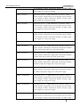
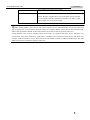
www.godynamix.com
FiberMix 831-120/120-BL User Manual
Legal Notices
Dynamix Pro., Ltd makes no warranty of any kind with regard to this manual, including,
but not limited to, the implied warranties of merchantability and fitness for a particular purpose.
Dynamix Pro., Ltd shall not be held liable for errors contained herein or direct, indirect, special,
incidental or consequential damages in connection with the furnishing, performance, or use of this
material.
Warranty.
A copy of the specific warranty terms applicable to your Dynamix product and replacement parts
can be obtained from Service Office.
Restricted Rights Legend.
All rights are reserved. No part of this document may be photocopied, reproduced, or translated to
another language without the prior written consent of Dynamix Pro., Ltd. The information
contained in this document is subject to change without notice.
Copyright Notices.
Copyright ©2007 Dynamix Pro., Ltd. All rights reserved.
No part of this publication may be excerpted, reproduced, translated or utilized in any form or by any
means, electronic or mechanical, including photocopying and microfilm, without permission in
Writing from Dynamix Pro., Ltd.
Trademark Notices
is the trademark of Dynamix Pro., Ltd.
Java™ is a U.S. trademark of Sun Microsystems, Inc.
Microsoft® is a U.S. registered trademark of Microsoft Corporation.
Windows NT® is a U.S. registered trademark of Microsoft Corporation.
Windows® 2000 is a U.S. registered trademark of Microsoft Corporation.
Windows® XP is a U.S. registered trademark of Microsoft Corporation.
Windows® and MS Windows® are U.S. registered trademarks of
Microsoft Corporation.
Contact Information
World Wide Web
You can access the most current Raisecom product information on the World Wide Web at the
following URL:
http://www.godynamix.com
http://www.dynamix.ua
Feedback
Comments and questions about how the FM831-120(-BL) device works are welcomed. Please review
the FAQ in the related manual, and if your question is not covered, send email by using the following
web page:
http://www.godynamix.com/ukr/cont.html
If you have comments on the device specification, instead of the web page above, please send
comments to:
[email protected]
[email protected]
We hope to hear from you!
CONTENTS
Release Notes------------------------------------------------------------------------------------------------- 5
General Safety Instructions ------------------------------------------------------------------------------ 6
Chapter 1
1.1
1.2
1.3
Product Overview ------------------------------------------------------------------------- 1
Overview---------------------------------------------------------------------------------------------------------------------1
Function Features ---------------------------------------------------------------------------------------------------------1
Ordering information------------------------------------------------------------------------------------------------------1
Chapter 2
Technical Specifications ---------------------------------------------------------------- 4
2.1 Technical specifications of E1 interface ---------------------------------------------------------------------------------4
2.2 Technical specifications of the optical interface -----------------------------------------------------------------------4
2.3 The properties of the Agent network management interface-------------------------------------------------------4
2.4 Power supply -------------------------------------------------------------------------------------------------------------------5
2.5 Operating environment-------------------------------------------------------------------------------------------------------5
2.6 Storing environment ----------------------------------------------------------------------------------------------------------5
2.7 Outline and structure ---------------------------------------------------------------------------------------------------------5
Chapter 3
Device Appearance and Descripiton------------------------------------------------ 6
3.1 Device front panel -------------------------------------------------------------------------------------------------------------6
3.2 Device rear panel--------------------------------------------------------------------------------------------------------------6
3.3 Indicator Description----------------------------------------------------------------------------------------------------------7
3.4 Interface description ----------------------------------------------------------------------------------------------------------9
Chapter 4
Device Settings --------------------------------------------------------------------------10
4.1 DIP switch description------------------------------------------------------------------------------------------------------ 10
4.1.1 The location of the DIP switches ----------------------------------------------------------------------------------------------------- 10
4.1.2 DIP switch description ------------------------------------------------------------------------------------------------------------------ 10
4.1.3 Default settings --------------------------------------------------------------------------------------------------------------------------- 13
Chapter 5
Basic Connection and Typical Application -------------------------------------15
5.1 Basic Connection------------------------------------------------------------------------------------------------------------ 15
5.1.1 Connect the optical interface ---------------------------------------------------------------------------------------------------------- 15
5.1.2 Connect the E1 interface --------------------------------------------------------------------------------------------------------------- 16
5.1.3 Connect the Agent network management interface ----------------------------------------------------------------------------- 16
5.1.4 Connect to the power supply ---------------------------------------------------------------------------------------------------------- 16
5.2 Typical application----------------------------------------------------------------------------------------------------------- 16
Chapter 6
Network Management Features ----------------------------------------------------17
6.1 Network management platform ------------------------------------------------------------------------------------------ 17
6.2 Network management query --------------------------------------------------------------------------------------------- 17
6.3 Network management configuration------------------------------------------------------------------------------------ 17
Chapter 7
Device Installation Preparation and Connection -----------------------------18
7.1 Pre-installation checking and preparing ------------------------------------------------------------------------------- 18
7.1.1 Make sure that the E1 cable applied meet the requirement of the device------------------------------------------------- 18
7.1.2 Make sure that the fiber applied matches the requirement of the device -------------------------------------------------- 18
7.1.3 Confirm the fiber cable type applied------------------------------------------------------------------------------------------------- 18
7.2 Installation procedures ----------------------------------------------------------------------------------------------------- 18
7.2.1 Device installation------------------------------------------------------------------------------------------------------------------------ 18
7.2.2 Cable connection------------------------------------------------------------------------------------------------------------------------- 18
7.2.3 Device electrifying ----------------------------------------------------------------------------------------------------------------------- 19
Appendix A Cable Making--------------------------------------------------------------------------------20
B.1 E1 cable making------------------------------------------------------------------------------------------------------------- 20
B.2 PC-Agent network management cable making --------------------------------------------------------------------- 21
Appendix B FAQ --------------------------------------------------------------------------------------------22
Release Notes
Date of Release
Manual Version
Revisions
20071116
200706
REV.A
General Safety Instructions
The following instructions serve as a general guide for the safe installation and operation of telecommunications
products. Additional instructions, if applicable, are included inside the manual.
Safety Symbols
This symbol may appear on the equipment or in the text. It indicates potential
safety hazards regarding product operation or maintenance to operator or service
personnel.
Danger of electric shock! Avoid any contact with the marked surface while the
product is energized or connected to outdoor telecommunication lines.
Protective earth: the marked lug or terminal should be connected to the building
protective earth bus.
Some products may be equipped with a laser diode. In such cases, a label with
the laser class and other warnings as applicable will be attached near the optical
transmitter. The laser warning symbol may be also attached.
Please observe the following precautions:
• Before turning on the chassis with optic module, make sure that the fiber optic
cable is intact and is connected to the transmitter.
• Do not attempt to adjust the laser drive current.
• Do not use broken or unterminated fiber-optic cables/connectors or look straight at the
laser beam.
• The use of optical devices with the equipment will increase eye hazard.
• Use of controls, adjustments or performing procedures other than those specified herein, may
result in hazardous radiation exposure.
ATTENTION: The laser beam may be invisible!
Always observe standard safety precautions during installation, operation and maintenance of this
product. Only qualified and authorized service personnel should carry out adjustment, maintenance
or repairs to this product. No installation, adjustment, maintenance or repairs should be performed by
either the operator or the user.
All extension slots are not hot-swappable
Before operating modules in the electricity conditions, please be noticed that optical transceivers
shall be connected with optical fiber wires or shield with optical transceiver cover for fear that laser
light harms to operator’s eyes.
Handling Energized Products
General Safety Practices
Do not touch or tamper with the power supply when the power cord is connected. Line voltages may
be present inside certain products even when the power switch (if installed) is in the OFF position or
a fuse is blown. For DC-powered products, although the voltages levels are usually not hazardous,
energy hazards may still exist.
Before working on equipment connected to power lines or telecommunication lines, remove jewelry
or any other metallic object that may come into contact with energized parts.
Unless otherwise specified, all products are intended to be grounded during normal use. Grounding
is provided by connecting the mains plug to a wall socket with a protective earth terminal. If an earth
lug is provided on the product, it should be connected to the protective earth at all times, by a wire
with a diameter of 18 AWG or wider. Rack-mounted equipment should be mounted only in earthed
racks and cabinets.
Always make the ground connection first and disconnect it last. Do not connect telecommunication
cables to ungrounded equipment. Make sure that all other cables are disconnected before
disconnecting the ground.
Connection of AC Mains
Make sure that the electrical installation complies with local codes.
Always connect the AC plug to a wall socket with a protective ground.
Always connect the power cord first to the equipment and then to the wall socket. If a power switch
is provided in the equipment, set it to the OFF position. If the power cord cannot be readily
disconnected in case of emergency, make sure that a readily accessible circuit breaker or emergency
switch is installed in the building installation.
Connection of DC Mains
Unless otherwise specified in the manual, the DC input to the equipment is floating in reference to
the ground. Any single pole can be externally grounded.
Due to the high current capability of DC mains systems, care should be taken when connecting the
DC supply to avoid short-circuits and fire hazards.
DC units should be installed in a restricted access area, i.e. an area where access is authorized only to
qualified service and maintenance personnel.
Make sure that the DC supply is electrically isolated from any AC source and that the installation
complies with the local codes.
Before connecting the DC supply wires, ensure that power is removed from the DC circuit. Locate
the circuit breaker of the panel board that services the equipment and switch it to the OFF position.
When connecting the DC supply wires, first connect the ground wire to the corresponding terminal,
then the positive pole and last the negative pole. Switch the circuit breaker back to the ON position.
A readily accessible disconnect device that is suitably rated and approved should be incorporated in
the building installation.
Preventing Electrostatic Discharge Damage
Modules which can be plugged into chassis are sensitive to damage from static electricity.
Conversely, static voltages as high as 35,000V can be generated just by handling plastic or foam
packing material, or by sliding assemblies across plastic and carpets. Not exercising the proper
electrostatic discharge (ESD) precautions can result in intermittent or complete component failures.
To minimize the potential for ESD damage, observe the following guidelines:
• Always use an ESD-preventive antistatic wrist strap or ankle strap and ensure that it makes good
skin contact.
• When removing or installing a component, make sure the equipment end of your antistatic strap
leash is connected to the ESD connection sockets on the front of the chassis or to a bare metal
surface on the chassis. Avoid contact between the component and your clothing. The wrist strap only
protects the component from ESD voltages on the body; ESD voltages on your clothing can still
cause component damage.
• Always place a card component-side-up on an antistatic surface, in an antistatic card rack, or in a
static shielding bag. If you are returning the item to the factory, immediately place it in a static
shielding bag.
• Handle Modules by the metal card carrier edges only; Avoid touching the board or any connector
pins.
www.godynamix.com
User Manual
Chapter 1 Product Overview
1.1 Overview
FM831-120/120-BL is a stand-alone single-optical-port PDH multiplexer independently developed
by Dynamix Pro., Ltd. FM831-120/120-BL is a fiber transmission device aiming at
network access market. The height of the device is 1U. It can transmit at most 4 lines of E1 data on 1
line of fiber and realize local as well as remote network management at the same time.
1.2 Function Features
¾
¾
¾
¾
¾
¾
¾
¾
Local and remote device manageable
In support of SNMP network management
Indication for both local and remote site alarms
Remote device power-off detection and alarm notification
ALS function is supported to effectively control the output of optical signal in no connection
status
At most 4 E1 interfaces working at 2048Kbps transparent transmission mode
Local and remote loopback testing function makes fault removal easier
Power consumption < 10W, and stable and reliable operation is guaranteed.
Adopt grand-scale ASIC chip
Low power consumption
4-layer circuit board design guarantees high reliability.
1.3 Ordering information
Device Model
Description
FM831-120-M
Stand-alone device, 4 75Ω unbalanced E1 interfaces (BNC), 1
optical interface, dual-strand, multi-mode, transmission distance
0~2km, single power supply, AC or DC power supply
FM831-120-S1
Stand-alone device, 4 75Ω unbalanced E1 interfaces (BNC), 1
optical interface, dual-strand, single-mode, transmission distance
0~25km, single power supply, AC or DC power supply
FM831-120-S2
Stand-alone device, 4 75Ω unbalanced E1 interfaces (BNC), 1
optical interface, dual-strand, single-mode, transmission distance
10~60km, single power supply, AC or DC power supply
FM831-120-S3
Stand-alone device, 4 75Ω unbalanced E1 interfaces (BNC), 1
optical interface, dual-strand, single-mode, transmission distance
15~120km, single power supply, AC or DC power supply
FM831-120-SS13
Stand-alone device, 4 75Ω unbalanced E1 interfaces (BNC), 1
optical interface, single-strand, two-wavelength, optical interface
1
www.godynamix.com
User Manual
Tx wavelength 1310nm, transmission distance 0~25km, single
power supply, AC or DC power supply
FM831-120-SS15
Stand-alone device, 4 75Ω unbalanced E1 interfaces (BNC), 1
optical interface, single-strand, two-wavelength, optical interface
Tx wavelength 1550nm, transmission distance 0~25km, single
power supply, AC or DC power supply
FM831-120-SS23
Stand-alone device, 4 75Ω unbalanced E1 interfaces (BNC), 1
optical interface, single-strand, two-wavelength, optical interface
Tx wavelength 1310nm, transmission distance 10~50km, single
power supply, AC or DC power supply
FM831-120-SS25
Stand-alone device, 4 75Ω unbalanced E1 interfaces (BNC), 1
optical interface, single-strand, two-wavelength, optical interface
Tx wavelength 1550nm, transmission distance 10~50km, single
power supply, AC or DC power supply
FM831-120-BL-M
Stand-alone device, 4 120Ω balanced E1 interfaces (RJ-45), 1
optical interface, dual-strand, multi-mode, transmission distance
0~2km, single power supply, AC or DC power supply
FM831-120-BL-S1
Stand-alone device, 4 120Ω balanced E1 interfaces (RJ-45), 1
optical interface, dual-strand, single-mode, transmission distance
0~25km, single power supply, AC or DC power supply
FM831-120-BL-S2
Stand-alone device, 4 120Ω balanced E1 interfaces (RJ-45), 1
optical interface, dual-strand, single-mode, transmission distance
10~60km, single power supply, AC or DC power supply
FM831-120-BL-S3
Stand-alone device, 4 120Ω balanced E1 interfaces (RJ-45), 1
optical interface, dual-strand, single-mode, transmission distance
15~120km, single power supply, AC or DC power supply
FM831-120-BL-SS13
Stand-alone device, 4 120Ω balanced E1 interfaces (RJ-45), 1
optical interface, single-strand, two-wavelength, optical interface
Tx wavelength 1310nm, transmission distance 0~25km, single
power supply, AC or DC power supply
FM831-120-BL-SS15
Stand-alone device, 4 120Ω balanced E1 interfaces (RJ-45), 1
optical interface, single-strand, two-wavelength, optical interface
Tx wavelength 1550nm, transmission distance 0~25km, single
power supply, AC or DC power supply
FM831-120-BL-SS23
Stand-alone device, 4 120Ω balanced E1 interfaces (RJ-45), 1
optical interface, single-strand, two-wavelength, optical interface
Tx wavelength 1310nm, transmission distance 10~50km, single
2
www.godynamix.com
User Manual
power supply, AC or DC power supply
FM831-120-BL-SS25
Stand-alone device, 4 120Ω balanced E1 interfaces (RJ-45), 1
optical interface, single-strand, two-wavelength, optical interface
Tx wavelength 1550nm, transmission distance 10~50km, single
power supply, AC or DC power supply
LNote: Among FM831 series devices with optical transceivers for dual-strand fiber, the devices with same
optical transceivers can inter-connect with each other. For example, FM831-120-S1 can be inter-connected with
FM831-240-S1, FM831-240-BL-S1 and other FM831 series devices with S1 optical transceivers.
Among FM831 series devices adopting optical transceivers for single-strand fiber, device with SS13 can
communicate with device with SS15, while device with SS23 can communicate with device with SS25. For
example, FM831-120-SS13 can be inter-connected with FM831-120-SS15, FM831-120-BL-SS15 and other
FM831 series devices with SS15 optical transceivers.
3
www.godynamix.com
User Manual
Chapter 2 Technical Specifications
2.1 Technical specifications of E1 interface
¾
¾
¾
¾
¾
¾
¾
Bit rate: 2048Kbps±50ppm
Coding: HDB3
Interface type: BNC, RJ-45
Interface impedance: 75Ω unbalanced interface, 120 Ω balanced interface
Physical characteristic: comply with ITU-T G.703 recommendations
Transfer characteristic: comply with ITU-T G.823 recommendations
Jitter tolerance: comply with ITU-T G.823 recommendations
2.2 Technical specifications of the optical interface
¾
¾
¾
¾
Bit rate: 150Mbps
Line coding: scrambled NRZ
Interface type: SC interface (FC interface made to order)
Optical transmission parameter: different optical transceivers have different optical interface
parameters, please see the table below.
Optical
transceiver
Wavelength
(nm)
Transmitting
Optical
Power (dBm)
Overload
(dBm)
Extinction
Ratio (dB)
Receiving
Sensibility
(dBm)
Transmission
Distance
(Km)
M
1310
-20 ~ -14
> -14
> 8.2
< -28
0~2
S1
1310
-15 ~ -8
> -8
> 8.2
< -34
0 ~ 25
S2
1310
-5 ~ 0
> -8
> 8.2
< -34
10 ~ 60
S3
1550
-5 ~ 0
> -10
> 10
< -36
15 ~ 120
SS13
1310
-12 ~ -3
> -8
> 8.2
< -30
0 ~ 25
SS15
1550
-12 ~ -3
> -8
> 8.2
< -30
0 ~ 25
SS23
1310
-5 ~ 0
> -8
> 8.2
< -32
10 ~ 50
SS25
1550
-5 ~ 0
> -8
> 8.2
< -32
10 ~ 50
LNote: The transmission distance in the table indicates the maximal transmission distance in typical optical
fiber condition. The transmission distance that can be realized depends on the factual status of the network.
2.3 The properties of the Agent network management interface
¾
¾
Interface type: RJ-45
Standard Compliance: RS232
4
www.godynamix.com
¾
User Manual
Bit rate: 19200bps
2.4 Power supply
AC power supply
¾
¾
¾
or:
¾
¾
¾
Voltage: 220V
Allowance: 175 ~ 265V
Frequency: 50Hz
Voltage: 110V/230V
Allowance: 85 ~ 265V
Frequency: 50Hz/60Hz
DC power supply
¾
¾
or:
¾
¾
Voltage: -48V
Allowance: -36 ~ -72V
Voltage: +24V
Allowance: +18 ~ +36V
Power consumption: < 10W
2.5 Operating environment
¾
¾
Operating temperature: 0 ~ 60℃
Operating humidity: ≤ 90% (25℃)
2.6 Storing environment
¾
¾
Storing temperature: -40 ~ 80℃
Storing humidity: 5% ~ 90%, no condensation
2.7 Outline and structure
¾
¾
¾
Physical outline: 19” stand-alone device, 1U in height
Dimension: 43.6mm (Height) x 440mm (Width) x 180mm (Depth)
Net Weight: 2.5Kg
5
www.godynamix.com
User Manual
Chapter 3 Device Appearance and Descripiton
3.1 Device front panel
Figure 3-1 The front panel of FiberMix 831-120
Figure 3-2 The front panel of FiberMix 831-120-BL
3.2 Device rear panel
Figure 3-3 The rear panel of FiberMix 831-120 with AC power supply
Figure 3-4 The rear panel of RC831-120 with DC power supply
6
www.godynamix.ua
User Manual
Figure 3-5 The rear panel of FiberMix 831-120-BL with AC power supply
Figure 3-6 The rear panel of FiberMix 831-120-BL with DC power supply
3.3 Indicator Description
Figure 3-7 The front panel of FiberMix 831-120
Figure 3-8 The front panel of FiberMix 831-120-BL
7
www.godynamix.com
User Manual
The indicators on the front panel of the device show the current operating status of the power supply,
optical interface, and E1 interface. Take FM831-120 as an example, the indicators are described in
the table below.
Serial
Number
Title
Color
Description
1
ALM
Red
Total alarm indicator.
ON: any one of the local alarms occurs.
Flickering: no local alarm but remote alarm
occurs
OFF: no local/remote alarm
2
PWR
Green
Power supply indicator.
ON: the power supply is operating normally.
3
LPR
Red
Remote device power-off indicator.
ON: both the local device and the remote device
are working normally when the power supply of
the remote device is down.
OFF: other status
4
L LOS
Red
ON: loss of signal at the local optical interface
5
R LOS
Red
ON: loss of signal at the remote optical interface
6
L LOF
Red
ON: loss of frame at the local optical interface
7
R LOF
Red
ON: loss of frame at the remote optical interface
8
L E-3
Red
ON: the Bit Error Rate(BER) at the local optical
interface exceeds 1E-3
9
R E-3
Red
ON: the BER at the remote optical interface
exceeds 1E-3
10
L E-6
Yellow
ON: the BER at the local optical interface
exceeds 1E-6
11
R E-6
Yellow
ON: the BER at the remote optical interface
exceeds 1E-6
12~15
LOS 1~4
Red
The indicators for Loss of signal (LOS) alarm at
E1 1~4.
ON: local E1 LOS alarm
Flickering: remote E1 LOS alarm
8
www.godynamix.com
User Manual
OFF: no LOS alarm at both local and remote E1
interface
Reserved
24~27
3.4 Interface description
A PC-AGENT interface for network management is placed on the front panel of the device. The
interfaces are described in the table below:
Serial
Number
Title
Interface
Description
28
LNK-DWN
RJ-45
Cascade interface.
Connect to the LNK-UP interface of the
device on the lower level of the cascade.
Comply with RS232 electrical level
standard. The port will be working at the
rate of 19200bps.
LNK-UP
29
RJ-45
Local network management interface or
cascade interface.
Connect to the serial port of the PC for
network management or connect to the
LNK-DWN interface of the device on the
higher level of the cascade. Comply with
RS232 electrical level standard. The port
will be working at the rate of 19200bps.
E1 interfaces are placed on the rear panel of the device. Please see the table below for the description
of the unbalanced E1 interfaces for FM831-120.
E1 interface 1~4
Interface
Description
BNC
75Ω unbalanced E1 interface 1~4
Description:
FM831-120-BL and RC831-120 use different E1 interfaces. The balanced E1 interfaces for
FM831-120-BL are described in the table below:
E1 interface 1~4
Interface
Description
RJ-45
120Ω balanced E1 interface 1~4
9
www.godynamix.com
User Manual
Chapter 4 Device Settings
4.1 DIP switch description
4.1.1 The location of the DIP switches
The DIP switches are placed on the front panel of FM831-120 and FM831-120-BL (see Figure 3-7
and Figure 3-8). We take the DIP switches of FM831-120 as an example.
4.1.2 DIP switch description
The DIP switches on the device front panel are for the control of the optical interface and the E1
interfaces. For detailed description of these DIP switches, please refer to the following four tables
(Table 4-1, Table 4-2, Table 4-3 and Table 4-4).
Table 4-1 The MASK button on the front panel of the FM831-120
Serial
Number
Title
Number
of Bits
Description
20
MASK
1 bit
Mask the traps from E1 lines that are not
used at the local site.
Press out the bit, the traps will not be
masked.
Press in the bit, the traps will be masked.
Table 4-2 The ADDR DIP switch on the front panel of FM831-120
Serial
Number
Title
Numbers
of Bits
21
ADDR
4 bits
Description
Bit
4
Bit
3
Bit
2
Bit
1
Device
Type
OFF
OFF
OFF
OFF
Remote
Device
OFF
OFF
OFF
ON
Local
Device
No.1
OFF
OFF
ON
OFF
Local
Device
No. 2
OFF
OFF
ON
ON
Local
Device
10
www.godynamix.com
User Manual
No.3
OFF
ON
OFF
OFF
Local
Device
No.4
OFF
ON
OFF
ON
Local
Device
No.5
OFF
ON
ON
OFF
Local
Device
No.6
OFF
ON
ON
ON
Local
Device
No.7
ON
OFF
OFF
OFF
Local
Device
No.8
ON
OFF
OFF
ON
Local
Device
No.9
ON
OFF
ON
OFF
Local
Device
No.10
ON
OFF
ON
ON
Local
Device
No.11
ON
ON
OFF
OFF
Local
Device
No.12
ON
ON
OFF
ON
Local
Device
No.13
ON
ON
ON
OFF
Local
Device
No.14
ON
ON
ON
ON
Local
Device
No.15
11
www.godynamix.com
User Manual
ADDR switches are used for configure the management
address of PC Agent. As a local device,
RC831-120/120-BL can be managed by the serial port of
the local PC through PC Agent cable connecting the
LNK-UP interface. The devices in the cascade of one
serial port are not allowed to have identical ADDR code.
At most 15 devices are allowed in one local cascade.
Table 4-3 DIP switch SEL on the front panel of FM831-120
Serial
Number
Title
Number
of Bits
Description
22
SEL
4 Bits
Bit 1: Auto Laser Shutdown (ALS) function
setting of the optical interface
Bit 1 = OFF: the ALS function of the optical
interface is disabled.
Bit 1 = ON: the ALS function of the optical
interface is enabled.
Bit 2: system online upgrade function setting
Bit 2 = OFF: the online upgrade function is
turned OFF
Bit 2 = ON: the online upgrade function is
turned ON
Bit 3: reserved bit
Bit 4: local/remote E1 loopback setting
Bit 4 = OFF: E1 remote loopback
Bit 4 = ON: E1 local loopback
Table 4-4 DIP switch E1-LOOP on the front panel of FM831-120
Serial
Number
Title
Number
of Bits
Description
23
E1-LOOP
4 bits
Bit 1~4: control of the loopback of E1
1~4
Bit 1 = OFF: loopback of E1 1 is
disabled.
Bit 1 = ON: loopback of E1 1 is enabled
Bit 2~4: enable or disable loopback of
12
www.godynamix.com
User Manual
E1 2~4, same way as Bit 1
Multiplexing Core
Interface
Interface Circuit
Multiplexing Core
Circuit
When executing E1 loopback testing, the Bit 4 of DIP switch SEL is used for selecting the loopback
point, that is, deciding whether the loopback is a remote loopback or a local one. The E1 loopback of
RC831 series device has two directions. The loopback point and loopback direction of the remote
loopback and local loopback are shown in the Figure 4-1 and Figure 4-2.
Figure 4-1 The settings of “remote loopback” on the local PDH multiplexer
Fiber
BER Tester
E1
Sid
e
E1
Local
Sid
e
Remot
e
Figure 4-2 The settings of the “local loopback” on the local PDH multiplexer
LNote:
1. Before setting up the E1 remote loopback testing, please make sure that there is no alarm at the
optical interface.
2. To set up any loopback on the local PDH multiplexer, the setting of all bits of DIP switch
E1-LOOP on the device at the opposite site must be of the default setting, which is OFF.
3. Please mask all false alarms from E1. If some of the E1 lines (not all of them) are well connected
and there are no LOS alarms on them, the LOS alarm indicators of those unconnected E1 lines will
turn ON and they are false alarms. In this circumstance, press in the MASK switch and all local false
alarms will be masked and disappear, and the corresponding E1-LOS indicators will turn OFF. For
those well-connected E1 lines, the indication for the LOS alarms on them will not be affected by the
change of the status of the MASK switch.
4. The online upgrade function is only applicable when the device is set to be a local site device.
Note that when applying the device normally, please make sure that the online upgrade function is
OFF before electrifying the device. Otherwise, the MCU can not get start.
4.1.3 Default settings
The factory settings of all DIP switches are OFF.
This default setting of the device indicates that:
13
www.godynamix.com
User Manual
The device is a remote device.
The ALS function is disabled.
No E1 local/remote loopback.
Unmask all E1 LOS alarm.
14
www.godynamix.com
User Manual
Chapter 5 Basic Connection and Typical Application
5.1 Basic Connection
5.1.1 Connect the optical interface
Insert the well-prepared fiber patch cord into the optical interface on the front panel of the device.
For device adopting optical transceivers M, S1, S2 or S3, the optical interface connection pattern is
shown in Figure 5-1. On the device panel, “TX” indicates output optical signal, while “RX” indicates
input optical signal.
Figure 5-1 The connection of the optical interface - 1
For device adopting optical transceiver SS13, SS15, SS23 or SS25, the optical interface connection
manner is shown in Figure 5-2. In this circumstance, the optical interface will receive as well as
transmit signals. “TX” and “RX” on the device panel have no meaning. For details, please refer to
the ordering information in section 1.3.
Figure 5-2 The connection of the optical interface – 2
15
www.godynamix.com
LNote:
User Manual
Only inter-connection of optical transceiver SS13 and SS15 and inter-connection of optical
transceiver SS23 and SS25 are allowed. Same type of optical transceivers can not communicate.
If the connection is correct, and there is receiving optical signal, the LOS alarm indicator on the front
panel of the device will turn OFF after the device being electrified.
5.1.2 Connect the E1 interface
FM831-120-BL adopts twisted pair with RJ-45 connector to connect the 120Ω balanced E1interface
on the device. For the pin arrangement of the RJ-45 connector and relevant cable making method,
please refer to Appendix A.
FM831-120 adopts coaxial cable with BNC connector to connect the 75Ω unbalanced E1 interface.
For the cable making of coaxial cable with BNC connector, please refer to Appendix A.
5.1.3 Connect the Agent network management interface
When connecting the device with the PC for network management, please connect the RJ-45
connector of the CBL-PCAGENT-DB9F/RJ45 cable to the LNK_UP interface of the device and
connect the DB-9 connector of the cable to the serial port of the PC.
When forming a cascade, please connect the LNK_DWN interface of the higher-level device and the
LNK_UP interface of the lower-level device using RJ-45 to RJ-45 flat cable.
5.1.4 Connect to the power supply
For device adopting 220V AC power supply, please plug the provided 220V AC power supply cable
to a 220V standard 3-phase power supply socket. For device adopting -48V DC power supply, please
connect the device with DC power supply using -48V DC power supply (connect the BGND
terminal of the DC power supply interface of the device to the 0V ground of the power supply,
connect the -48V terminal to the -48V power supply, and connect the PGND terminal to protection
earth). For device using +24V DC power supply, the connecting is similar to that of the -48V DC
power supply.
5.2 Typical application
FM831
OOP ECOP
W1 L
M
L
R
W2 W
KK
I
1
OE
3E
6
-
SS2
AB
B
F
EO
1
T
F
KC
H
1 2 3 4 56 7 8 0 N D
TM
E1
D
TE L
D
1234 5678
FM831
Fiber
EC O
M
P
W 1L
P
P
W2 W
OO
L
R
K KI
O
SS
2
A BB F
3E
E
6
-
1
EO
K
1
T
D
C
F
13
2 4 56 78 0 M
HD
N T
TE L
D
1234 5 678
P
0
E1
RS232
Agent
Figure 5-3 Point-to-point application
16
www.godynamix.com
User Manual
Chapter 6 Network Management Features
6.1 Network management platform
The status information of FM831-120/120-BL devices can be viewed on Dynamix’s network
management platform NView NNM V5.0. Users can also control or configure the device on the
platform.
6.2 Network management query
The status of all indicators on the local/remote FM831-120/120-BL device will be displayed on the
network management platform. The current configuration information and alarm information of E1
service can be queried on the platform.
6.3 Network management configuration
Users can change the settings of all DIP switches except for DIP switch ADDR through the network
management platform.
LNote: The latest configuring operation, whether it is completed by the network management
system or a DIP switch, will always take effect.
17
www.godynamix.com
User Manual
Chapter 7 Device Installation Preparation and Connection
7.1 Pre-installation checking and preparing
Firstly, please check the model and the number of the device and spare parts according to the packing
list. Please be sure that the appearance of the device is intact. If there is any evidence that the device
has been affected by damp, please dry it before installation.
Please read this manual with caution before installing the device; please have all types of cables that
are needed ready and make sure there are no short circuits and open circuits; please make sure that
the power supply of the chassis works in the operating voltage range; please have the rack of the
chassis device well earthed; please prepare BER tester, optical power meter for line quality testing;
please fix the device on to a 19-inch rack or place it on a safe and stable place, please be cautious of
the environment requirement of the device.
7.1.1 Make sure that the E1 cable applied meet the requirement of the device
If the E1 line to which the FM831-120/120-BL will connect to is composed of PDH and SDH
devices, please refer to the user manual of the corresponding device for parameters like E1 interface
type, definition and impedance.
7.1.2 Make sure that the fiber applied matches the requirement of the device
For FM831-120/120-BL-M, please use multi-mode fiber with SC/PC connector.
For FM831-120/120-BL-S1/S2/S3, please use single-mode fiber with SC/PC connector.
For FM831-120/120-BL-SS13/SS15/SS23/SS25, please use single-mode fiber with SC/PC
connector.
7.1.3 Confirm the fiber cable type applied
The cable type for the interface of multi-mode fiber:
62.5/125um multi-mode fiber or 50/125um multi-mode fiber
The cable type for the interface of single-mode fiber:
9/125um single-mode fiber
7.2 Installation procedures
7.2.1 Device installation
Please fix the device firmly.
7.2.2 Cable connection
Please connect the cables in need according to factual situation. For details, please refer to Chapter 5
for “Basic Connection and Typical Application”.
18
www.godynamix.com
User Manual
7.2.3 Device electrifying
Please tighten the connection and make sure there is no loose connection, and then turn on the power
supply. The power supply status indicator PWR (Green) on the front panel of the device will turn ON
to show that the power supply is working normally.
The device will begin to initialize and self-check after electrifying. The process will take no more
than 10 seconds. During the initialization and self-checking, the optical interface status indicator
LOF and E-6 may flicker for one time, which is a normal phenomenon. The system will begin its
normal operation after 10 seconds.
During normal operation, please make sure that there is no alarm at the optical interface. If the
optical interface is correctly connected, there will be no LOS, LOF, E-3, and E-6 alarms.
19
www.godynamix.com
User Manual
Appendix A Cable Making
B.1 E1 cable making
For 75Ω BNC interface:
The application of coaxial cable of model SYV75-5, SYV75-3 or SYV75-2-2 is recommended.
Please keep the maximal length of the cable within 200 meters.
Take out the BNC connector from the appendix pack of the device, and screw off the protection
cover. Part the core and the shield of the coaxial cable, and set the protection cover on to the cable.
Weld the core of the cable and the core of the BNC connector and weld the shield of the cable and
that of the BNC connector. Fix the protection cover at the rear of the connector firmly.
TX — output unbalanced signal
RX — input unbalanced signal
120Ω RJ-45 interface:
Please use CAT-5 twisted pair cable with RJ-45 connector to connect to the device. For the figure of
the RJ-45 connector and its pin arrangement, please see Figure A-1 and Table A-1.
Figure A-1 The pin arrangement of RJ-45 crystal connector (top view)
Table A-1 RJ-45 connector pin arrangement for E1
Pin
Number
Definition
1
2
3
4
5
6
7
8
OUT+
OUT-
NC
IN+
IN-
NC
NC
NC
OUT+ — output positive signal of device
OUT- — output negative signal of device
IN+ — input positive signal of device
IN- — input negative signal of device
NC — no connection
20
www.godynamix.com
User Manual
B.2 PC-Agent network management cable making
For PC-Agent network management, please use flat straight-through cable with RJ-45 connector. The
RJ-45 connector and its pin arrangement are shown in Figure A-1 and Table A-2, A-3 respectively.
Table A-2 Pin arrangement of LNK_UP interface
Pin
Number
1
2
3
4
5
6
7
8
Definition
NC
NC
IN
GND
NC
NC
OUT
GND
Table A-3 Pin arrangement of the LNK_DWN interface
Pin
Number
1
2
3
4
5
6
7
8
Definition
NC
NC
OUT
GND
NC
NC
IN
GND
NC — no connection
OUT — output RS-232 signal
IN — input RS-232 signal
GND — grounding signal
Figure A-2 shows the connection rule from the LNK_UP interface (RJ-45) to the serial port of the PC
(DB-9 female).
Figure A-2 The connection of the device and the serial port of the PC
LNote:
When making cables, please adopt shielded cable in preference to meet the
electromagnetic compatibility requirements.
21
www.godynamix.com
User Manual
Appendix B FAQ
For some problems you may meet during installation and operation, please try to solve them
following the suggestions below. For the problems can not be solved using the following suggestions,
please contact with Raisecom or our distributors for technical support.
¾
The power supply indicator PWR (green) wouldn’t turn ON.
Please check whether the power supply cable of the device is well connected and whether the
power supply switch has been turned on.
¾
The optical interface LOS indicator (red) turns ON.
This indicates that loss of receiving signal (LOS) alarm occurs at the optical interface.
Firstly, please check whether the fiber is well connected to the optical interface.
Secondly, please form a self loop using the fiber (may need attenuation). If the alarm still
exists, please replace the fiber and again form a self loop using the new fiber. If the optical
interface LOS indicator is still ON, there is problem with the device.
¾
The optical interface LOF indicator (red) turns ON.
Loss of frame alarm of the receiving signal at the optical interface occurs. Optical signal has
been received, but the optical power may be around the critical receiving sensitivity. Please
measure the receiving optical power and make sure that the TX interface of the optical
interface of the remote device has been well connected.
¾
Optical interface indicator E-3 (red) turns ON.
The bit error rate of the receiving signal at the optical interface exceeds 1E-3. Please check
whether the optical interface has been well connected and please measure the receiving
optical power as well.
¾
Optical interface indicator E-6 (yellow) turns ON.
The bit error rate of the receiving signal at the optical interface exceeds 1E-6. The E-6 alarm
may occur when the device is just electrified. This is a normal phenomenon and will last at
most 10 seconds before the E-6 indicator turns OFF. If the E-6 alarm occurs during the
normal operation of the device, please check whether the optical interface is well connected
and please measure the optical power.
¾
Communication failed on the E1 line
Please check whether the E1 cables and the fiber are well connected, and check the status of
the E1-LOS indicators on the front panel of the device. At the same time, please check the
loopback function set by the DIP switch E1-LOOP and Bit 4 of the DIP switch SEL (please
refer to Chapter 4) and locate the problem.
¾
The E1 interface LOS (red) indicator turns ON.
E1 LOS alarm indicates lost of receiving signals at the E1 interface. There is no HDB3 code
input.
Please check whether the E1 cable has been connected properly, and whether the TX and RX
of the BNC cable are correctly connected.
22
Web: http://www.godynamix.com
Email: [email protected]