1
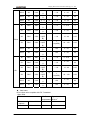
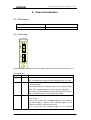
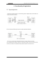
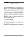
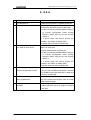
RC414 Universal Optical Converter/Repeater User Manual Beijing Raisecom Science & Technology Co., Ltd 10/2005 Beijing Raisecom Science & Technology Co., Ltd 1. Cautions Please read the following notices carefully before installing and using the device, Raisecom does not respond to any loss that caused by violating safety notice. RC414 provides optical port, and there is visible and invisible laser radiation when open. Do not stare into the beam or view directly with optical instruments and if the optical port is not used please insert the plug. RC414 is integrated device that has precise elements, please avoid violent shakes and impacts, and do not disassemble or maintain the device yourself. If it is required, please do it under the guide of our technical staff following in the steps of anti static. Please contact us if there is any need. There must be grounding protection for the sake of safety; do not disassemble the device yourself, we regard it as you waiver your rights of repair guarantee. 1 Beijing Raisecom Science & Technology Co., Ltd 1. 2. 3. 4. 5. 6. 7. 8. Catalog Cautions...........................................................................................................................1 Overview ..........................................................................................................................3 2.1. Introduction .......................................................................................................3 2.2. Product features.................................................................................................3 2.3. Ordering information ........................................................................................3 Parameters ......................................................................................................................4 3.1. Device specification ..........................................................................................4 3.2. Optical interface specifications .........................................................................4 View and indicators ........................................................................................................7 4.1. Dimensions........................................................................................................7 4.2. Front view .........................................................................................................7 Functionality & Application ............................................................................................9 5.1. Typical application ............................................................................................9 Installation & Preparation ............................................................................................10 6.1. Installation.......................................................................................................10 6.2. DIP switches configuration .............................................................................10 Network management..................................................................................................14 7.1. Show module...................................................................................................14 7.2. Configure module............................................................................................14 7.3. Module reset and loop back detection.............................................................15 Q & A ..............................................................................................................................16 2 Beijing Raisecom Science & Technology Co., Ltd 2. Overview 2.1. Introduction A single RC414 converter is used to connect two devices which are between a long distance or operating with dissimilar optic fiber mode (e.g. single mode and multi mode). And RC414 provides 2R (reshape and reamplify) function for services within the rate range of 42Mbps- 2.5GMbps and provides 3R function for standard rate services (GB, STM-4, STM-1 and FE). 2.2. Product features Multi rate: flexibly access fiber optic signals at rates of 1.25G or lower. Optical modules for different rates, different distances and different wavelengths are available for different customer needs, and you also can select relative optical connectors to achieve single/multi mode conversion. Transparently transmitting variable rate services: when you use high rate optical connector low rate services also can be transmitted (standard rate services of Gb, STM-4, STM-1, FE and other non-standard rate services are all included). Flexible debug function: provides fault pass through and fault return function on line side and client side for different customer needs. Retime function: a single RC414 converter has 3R function (Reshape, Reamplify and Retime), the low output jitter and client output jitter attenuating function can extending transmission distance. Loop back function: a single RC414 converter can provide bi-direction loop back function for system debug and device installation. 2.3. Ordering information RC414-XX-YY/ZZ Optical converter/ repeater RC414 Rate Optical Optical interface interface transmission transmission distance of distance of client side line side 3 Beijing Raisecom Science & Technology Co., Ltd C3:155M C12:622M Gb:1.25G C48:2.5G M S1 S2 S3 SS13 SS15 SS23* SS25* M S1 S2 S3 SS13 SS15 SS23* SS25* *note: optical connector type of SS23 and SS25 is only available at rate of C3. For example: RC414-Gb-M/S1 is 1000M single mode to multi mode optical converter RC414-C3-S2/S2 is 155M single mode to single mode optical converter/repeater. 3. Parameters 3.1. Device specification Dimension(H*W*D) 91mm×25mm×170mm Optical connector SC/PC Work temperature(℃) (0, 45) Storage temperature(℃) (-40, 80) Power consumption(W) Typical value: 3.5W Humidity 5%~90% non-condensing 3.2. Optical interface specifications Optical interface index is in the following table, and these are EOL (End Of Value) value: Over load point dBm Connector Wave length nm TX power dBm M DSC 1310 -18~ -14 -14 S1 DSC 1310 -15~ -8 -8 S2 DSC 1310 -5~0 -8 S3 DSC 1550 -5~ 0(DFB) -10 Rate Mbps Type FE/ STM-1 4 Optical RX sensitivity dBm (BER=E-1 0) Typical transmission distance Km Optical loss dB/Km < -29 0~2 3 < -34 0~25 0.5 < -34 10~60 0.5 < -36 15~120 0.25 Beijing Raisecom Science & Technology Co., Ltd SS13 SC 1310 -12~ -3 -8 SS15 SC 1550 -12~ -3 -8 SS23 SC 1310 -5~0 SS25 SC 1550 M DSC S1 DSC S2 DSC < -30 0~25 0.5 < -30 0~25 0.5 -8 < -32 10~50 0.5 -5~0 -8 < -32 10~50 0.5 850 -10~ -3 -3 < -17 0~0.55 3 1310 -10~ -3 -3 < -25 0~25 0.5 -3 1550 -3~ +2(DF B) < -22 10~60 0.25 -9 < -32(APD) 25~100 0.25 <-22 0~20 0.5 <-22 0~20 0.5 < -15 0~0.55 3 < -23 0~25 0.5 < -20 10~60 0.25 < -30(APD) 25~100 0.25 <-20 0~20 0.5 <-20 0~20 0.5 STM-4 S3 DSC 1550 -3~ +2(DF B) SS13 SC 1310 -10~ -3 -3 SS15 SC 1550 -10~ -3 -3 M DSC 850 -10~ -3 -3 S1 DSC 1310 -10~ -3 -3 -3 1550 -3~ +2(DF B) -9 S2 DSC Gb S3 DSC 1550 -3~ +2(DF B) SS13 SC 1310 -10~ -3 -3 SS15 SC 1550 -10~ -3 -3 Jitter index RC414 jitter value complies with ITU-T standard. 1 jitter value STM level STM-1 (optical) ITU-T requirement Typical value of RC414 1 500Hz-1.3MHz <0.30UI 0.050 65KHz-1.3MHz <0.10UI 0.030 5 Beijing Raisecom Science & Technology Co., Ltd STM-4 (optical) 1000Hz-5MHz <0.30UI 0.004 250KHz-5MHz <0.10UI 0.004 1 NOTE: this is the average value of many times measure by ACTERNA ANT-20 2 jitter transfer and jitter tolerance Typical figure of RC414 jitter transfer Typical figure of RC414 jitter tolerance 6 Beijing Raisecom Science & Technology Co., Ltd 4. View and indicators 4.1. Dimensions Dimension (H*W*D) W*L*H:91mm*25mm*170mm Weight (package is not included) 4.2. Front view LNK LCK LINE CLIENT LNK LCK RC414-Gb-S1/S3 Panel mesh print and interfaces are as above figure, the optical connector type is 1*9. LED indications: LED Color Indication PWR Green (power) ON: indicates power supply functioning normally; OFF: indicate power supply functioning abnormally or invalid. LNK Green (link) ON: indicates there is a valid link; OFF: indicates there is no input signal. LNK of client side ON: indicates there is input signal of client side; OFF: indicates there is no input signal of client side. LNK of line side ON: indicates there is input signal of line side; OFF: indicates there is no input signal of line side. LCK Green (lock) ON: indicates signal is locked; OFF: indicates signal is loss of lock. LCK of client side ON: indicates signal of RX channel (CLIENT->LINE) is locked; OFF: indicates signal of RX channel (CLIENT->LINE) is loss of lock. LCK of line side ON: indicates signal of TX channel 7 Beijing Raisecom Science & Technology Co., Ltd (LINE->CLIENT) is locked; OFF: indicates signal of TX channel (LINE->CLIENT) is loss of lock. 8 Beijing Raisecom Science & Technology Co., Ltd 5. Functionality & Application 5.1. Typical application i interconnect optical devices to convert fiber type from single mode to multi mode and extend transmission distance. ii RC414 Provides OEO relay function to extend transmission distance. RC414 can provide longer transmission distance through multilevel cascades. The cascade devices number of RC414 is not limited in theory. And we do the test uses 16 RC414 converters to cascade and we promise cascade 16 or fewer RC414. 9 Beijing Raisecom Science & Technology Co., Ltd 6. Installation & Preparation 6.1. Installation Slide RC414 into two adjacent installation slots and connect the fiber cable. If client side device and line side fiber are connected normally RC414 indicators LNK and LCK will be steady ON status. When install the device please be attention: 1 The connection sequence of fiber cables is not specified, but to satisfy the requirement of rate auto-sensing of single module (default setting enables rate auto-sensing), we recommend connect RX of client side fiber first (rate auto-sensing functioning normally when RX fiber of client side connects correctly). 2 Avoid Rx power of optical port is too high. Please do not connect optical port output with optical port input without attenuator, this may result in abnormal work of optical port or even damage it. Optical module of different rate and different transmission distance has different optical saturation power, usually optical power less than -8dBm will satisfy all the optical connectors. 3 Please set the rate of Ethernet services manually. In some peculiar case FE service may be regarded as GE service when use GE connectors, and in this condition there may be packet loss even if service connection is valid. 6.2. DIP switches configuration RC414 has 4 banks of DIP switches (SW1 is 4-bit switches and SW2-SW4 are 8-bit switches). SW1 is fault pass through and fault return function configuration switch, SW2 is CDR configuration switch, SW3 is line side optical port information switch and SW4 is client side optical port information switch. The entire DIP switches configuration is the module initialization configuration. And network management configuration has higher privilege than that of DIP switches except configuring loop back function. 10 Beijing Raisecom Science & Technology Co., Ltd SW1 function table(fault pass through and fault return function) Switch Status Function Mesh print Description Privilege SW1.1 On Fault-pass Line to Client FP_LC Fault pass through from line side to client side. Optical TX of client side will shutdown if there is no RX signal of line side. Off Normal Normal Normal. On Fault-pass Client to Line FP_CL Faults pass through from client side to line side. Optical TX of line side will shutdown if there is no RX signal of client side. Off Normal Normal Normal. On Fault-Return Line FR_L Fault return of line side. Line side TX of will shutdown if there is no RX signal. When pair uses RC414 this function is not allowed to enable at the same time by both ends. Off Normal Normal Normal. Network management configuration has higher privilege. This DIP switches configuration is valid when there is no network management. And when there is network management , network management configuration will be valid. On Fault-Return Client FR_C Fault return of client side. Client side TX of will shutdown if there is no RX signal. When pair uses RC414 this function is no allowed to enable at the same time by both ends. Normal Normal. SW1.2 SW1.3 SW1.4 Off Normal SW2 function table(CDR configuration DIP switches) Switch Status Function Description Reserved Reserved On Line Loop Line side loop back (forced) Off Normal Normal. Then module can be configured through network management and the default status is normal. On Client Loop Client side loop back (forced) Off Normal Normal. Then module can be configured through network management and the default status is normal. SW2.1 SW2.2 SW2.3 11 Privilege Force to set loop back and has higher privilege than network Management. Force to set loop back and has higher privilege than network Management. Beijing Raisecom Science & Technology Co., Ltd SW2.4 SW2.5 SW2.6 SW2.7 SW2.8 On CDR_Disable Disable CDR, in this condition the module has 2R function. Off CDR_Enable Enable CDR. On Manual Set rate manually according to SW2.6-8. Off Auto Controlled by CPU. When LOS indicator is off, RC414 will set CDR rate automatically from STM-16 to FE to accommodate the access data rate until there is no LOL (this indicates the module has locked that rate). These three bits are valid when SW2.5 is on. 2.6 2.7 2.8 Data rate Off Off Off C48 Off Off On Gb Off On Off C12 Off On On C3 On Off FE Off Other status Reserved Line side information switches SW3 Switch SW3.1-3.2 Status (N: on, F: off) Rate SW3.3-3.5 Reserved SW3.6-3.8 Distance Description FF 155M FN 622M NF 1.25G NN 2.5G(reserved) Reserved NNN M NNF S1 NFN S2 NFF S3 FNN SS13 FNF SS15 FFN SS23 FFF SS35 Client side information switches SW4 Switch SW4.1-4.2 Rate Status (N: on, F: off) Description FF 155M FN 622M 12 Network management configuration has higher privilege. Network management configuration has higher privilege. Beijing Raisecom Science & Technology Co., Ltd SW4.3-4.5 Reserved SW4.6-4.8 Distance NF 1.25G NN 2.5G(reserved) Reserved NNN M NNF S1 NFN S2 NFF S3 FNN SS13 FNF SS15 FFN SS23 FFF SS25 Default settings of SW1 and SW2 are OFF: fault pass through and fault return disable, loop back disable, CDR enable and rate auto-sensing enable. SW3 and SW4 stand for optical connector information and cannot be set by users. 13 Beijing Raisecom Science & Technology Co., Ltd 7. Network management RC414 can be controlled, configured and inquired through Raisecom network management system (EMS version is1.15 build 2 or higher). 7.1. Show module Use “Show module” to inquire RC414 status information: Number Status name, items can be Value controlled and configured Control and configure features C3, C12, GB M, S1, S2, S3, SS15, SS13 , SS25 and etc. Can be inquired but not configurable 1 Module type 2 Fault pass through from line Enable & Disable side to client side Can be inquired and configurable 3 Fault pass through from client Enable & Disable side to line side Can be inquired and configurable 4 Fault return of line side Enable & Disable Can be inquired and configurable 5 Fault return of client side Enable & Disable Can be inquired and configurable 6 Optical port of line side: LNK Up & Down status Can be inquired and configurable 7 Optical port of client side: LNK Up & Down status Can be inquired and configurable 8 Optical port of line side: LCK Loss Of status LOCK LOCK & Can be inquired and configurable 9 Optical port of client side: LCK Loss Of status LOCK LOCK & Can be inquired and configurable 10 CDR work status Enable & Disable Can be inquired and configurable 11 CDR rate GE/GB, STM4, STM1, FE and N/A Can be inquired and configurable 7.2. Configure module The configurable items can be configured through “Config module” in above table and these items include fault debug configuration and CDR configuration. Fault debug includes: fault pass through from line side to client side, fault pass through from client side to line side, line side fault return, client side fault return and etc; CDR configuration includes: enable or disable CDR and set the CDR rate as auto-sensing or forced rate. 14 Beijing Raisecom Science & Technology Co., Ltd 7.3. Module reset and loop back detection Host-site module can be reset through “Reset module” command. After reboot, the working mode and status will remain the same as that before reboot. Use “loop config” to set loop back of line side or client side for debug and installation. 15 Beijing Raisecom Science & Technology Co., Ltd 8. Q & A Fault Resolve 1 LNK indicator off Check the input power of relative optical port. 2 Client LNK on, and LCK off 1 check the input signal of client side. 2 check the optical RX power of client side. 3 if rate auto-sensing enables please change it to manual configuration mode through switches SW2.5 and set the rate through SW2.6-8. 4 if above steps still cannot resolve the problem, use SW2.4 to disable CDR. 5 contact technical staff of RAISECOM 3 Client LNK and LCK on Line LNK on and LCK off 1 check whether client side data and line side data is at same rate. 2 check optical power of optical port. 3 if rate auto-sensing enables please change it to manual configuration mode through switches SW2.5 and set the rate through SW2.6-8. 4 if above steps still cannot resolve the problem, use SW2.4 to disable CDR. 5 contact technical staff of RAISECOM 4 Rate auto-sensing failed but manual configuration normal Check optical interface information switches. There is the possibility that optical connector is 1000M but the input data rate is 100M. And set the rate manually. 5 Disconnect sometimes there is packet loss and Check the optical power of all optical ports first and if the power consumption value is normal set the rate manually. 6 Network management is not available Make sure that EMS version is 1.15 (build 4) or higher and MCU chip (U7) is tightly contacted with pad. 16 Beijing Raisecom Science & Technology Co., Ltd BROADBAND to RAISECOM @2005 Beijing Raisecom Science & Technology Co., Ltd. All trademarks are the property of their respective owners. Technical information may be subject to change without prior notification. 17