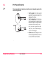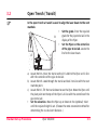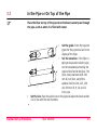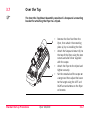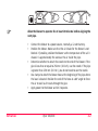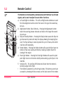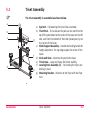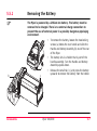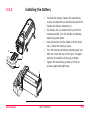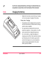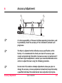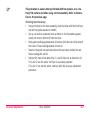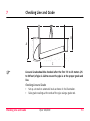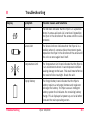
1
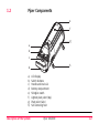
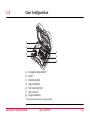
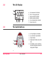
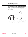
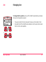
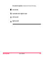
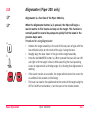
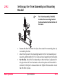
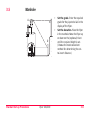
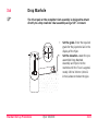
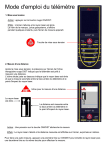
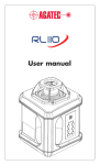
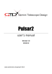
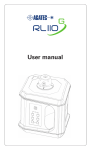
PIPER 100/200 User manual Version 2.0 English Introduction Purchase Congratulations on the purchase of a new Pipe Laser from Leica Geosystems. Product The Piper 100 and 200 are laser tools for pipe laying and other construction applications. They are designed and built with the latest innovations in the laser tool industry. They are easy to set up, simple to operate and highly dependable. This manual contains important safety directions as well as instructions for setting up the product and operating it. Refer to "10 Safety Directions" for further information. Read carefully through the User Manual before you switch on the product. Product identification The model and the serial number of your product are indicated on the type plate. Enter the model and serial number in your manual and always refer to this information when you need to contact your agency or Leica Geosystems authorized service workshop. Type: _______________ Serial No.: _______________ Piper 100/200 II Symbols The symbols used in this manual have the following meanings: Type Warning Danger Caution Trademarks Description Indicates an imminently hazardous situation which, if not avoided, will result in death or serious injury. Indicates a potentially hazardous situation or an unintended use which, if not avoided, could result in death or serious injury. Indicates a potentially hazardous situation or an unintended use which, if not avoided, may result in minor or moderate injury and/or appreciable material, financial and environmental damage. Important paragraphs which must be adhered to in practice as they enable the product to be used in a technically correct and efficient manner. • Alignmaster (registered trademark of Leica Geosystems) All trademarks are the property of their respective owners. Piper 100/200 III Table of Contents In this manual Chapter Page 1 Description of the System .......................................................1-1 2 Basic Operation .......................................................................2-1 3 Standard Set-up Procedures....................................................3-1 4 Refraction ................................................................................4-1 5 Accessories ..............................................................................5-1 6 Accuracy Adjustment ...............................................................6-1 7 Checking Line and Grade .........................................................7-1 8 Troubleshooting.......................................................................8-1 9 Care and Transport ..................................................................9-1 10 Safety Directions ...................................................................10-1 11 Technical Data .......................................................................11-1 Index .................................................................................................i-1 Piper 100/200 IV 1 Description of the System 1.1 Features Precision Engineered and designed to maintain its accuracy over time and temperature, the Piper projects a beam up to 200 meters (650 feet). Versatility Powered by a rechargeable Lithium-Ion battery, the Piper is the smallest, professional pipe laser ever made. When sitting level the Piper can self-level over its entire grade range, or can be placed inside the pipe for second day setups. In the manhole, in the pipe, or over the top, the Piper can work for you. Intelligence The cross-axis compensation function maintains the grade accuracy regardless of the roll of the laser up to three degrees. The Alignmaster™ feature (Piper 200) seeks and locates the target automatically for easy second day setups. Ruggedness Waterproof, shock and temperature tested, the Piper is built “construction tough” with a metal housing and shock absorbing bumper around the front window. Models There are two models of the Piper pipe laser described in this manual: • Piper 100 - Red beam pipe laser • Piper 200 - Red beam pipe laser with the Alignmaster™ feature. Description of the System Piper 100/200 1-1 1.2 Piper Components e f g a b c h d a) b) c) d) e) f) g) h) Description of the System LCD display Switch buttons Handle and level vial Battery compartment Stringline notch Lighted pivot point (top) Pivot point (side) Self-centering feet Piper 100/200 1-2 1.3 Case Configuration a b c d a) b) c) d) e) f) g) e f g Accessory compartment Piper* Remote control Spare batteries Self-centering feet User manual Target assembly * Piper shown with optional scope assembly Description of the System Piper 100/200 1-3 2 Basic Operation In this chapter Topic 2.1 2.2 2.3 2.4 2.5 2.6 2.7 2.8 2.9 Basic Operation Page Starting Up ..........................................................................2-2 The LCD Display...................................................................2-3 The Switch Buttons .............................................................2-3 Three Basic Requirements...................................................2-4 Entering Grade ....................................................................2-6 Changing Line......................................................................2-7 Line and Grade Lock............................................................2-9 Alignmaster (Piper 200 only).............................................2-11 General Procedures...........................................................2-13 Piper 100/200 2-1 2.1 Starting Up a) Press the POWER button to turn the Piper on. b) When the Piper is first turned on the Leica Start-up Screen is displayed with the serial number of the laser. c) Next, the Piper Screen will be displayed. d) Or the Customer Name Screen if it has been programmed by your dealer. e) Finally, the Battery Status Screen will be displayed as a large battery. f) Basic Operation When the start-up screens are completed, the Main Operating Screen will be displayed and work can begin. Piper 100/200 2-2 2.2 The LCD Display a b c 2.3 d f e Line movement indication Plus / minus grade value Beam emission indicator Battery status indicator Line and grade lock indicator Percent (per mil) The Switch Buttons a) b) c) d) a b c Basic Operation a) b) c) d) e) f) d e Piper 100/200 Left and Right Line Buttons Up and Down Grade Button Power Button Alignmaster Button, Piper 200 only e) Star Button, used in combination with the grade buttons for large grade changes 2-3 2.4 Three Basic Requirements Refer to the information that follows when setting up and operating the Piper. (To set up for a specific application, see the “Standard Set-up Procedures in this manual.) You must always define the following three variables in any application. • Basic Operation Grade - The amount of rise or fall over the distance of the pipe to be laid. Set the grade by entering the percent of grade into the Piper display. Piper 100/200 2-4 • Elevation - The distance from the invert of the pipe to the laser beam. This distance is set by attaching the self-centering feet for the pipe size to be laid (The 150 mm, six inch feet are standard. All other sizes are optional.) or by adjusting the height of the piper on the Trivet Mount Assembly. 5-TOP • Basic Operation Line - The position of the laser beam relative to the centerline of the pipe to be laid. Set the line by aligning the laser beam with the next manhole. Piper 100/200 2-5 2.5 a b c Entering Grade To change grade, press an UP or DOWN arrow button (a) to enter the grade required. • The speed at which the grade changes will increase as the button in held. • Press both the UP and DOWN arrow buttons (b) at the same time to reset the grade to zero. To make large changes of grade, first press and release the STAR button (c) when at the main operating screen. The plus / minus sign will appear as a reverse image. • Press the LEFT or RIGHT arrow buttons (d) to move the cursor (reverse image) to the desired digit. • Press the UP or DOWN arrow buttons (a) to change the plus / minus sign or the value of the individual digit. • Press both the UP and DOWN arrow buttons (b) at the same time to reset the grade to zero. • Press STAR (c) to exit when desired grade is displayed or wait ten seconds and the screen will automatically return to the main operating screen. d Basic Operation Piper 100/200 2-6 2.6 Changing Line To change the line position, press a LEFT or RIGHT arrow button (a) to move the beam to the position required • • a The speed at which the line moves will increase as the button in held. Press both the LEFT and RIGHT arrow buttons (b) at the same time to reset the line to the center position. b Basic Operation Piper 100/200 2-7 The current line position is indicated at the top of the display. Line Centered Line Position Left or Right of Center Left Line Limit Right Line Limit Basic Operation Piper 100/200 2-8 2.7 Line and Grade Lock To lock the grade position, press and hold the STAR button, then press an UP or DOWN arrow button (a) to lock the grade at the current value. To lock the line position, press and hold the STAR button, then press a LEFT or RIGHT arrow button (b) to lock the line at the current position. a To unlock grade or line, repeat the same procedure. b Basic Operation Piper 100/200 2-9 The current status is indicated at the bottom, center of the display. Grade and Line Unlocked Grade Locked Line Locked Grade and Line Locked Basic Operation Piper 100/200 2-10 2.8 a Alignmaster (Piper 200 only) Alignmaster is a function of the Piper 200 only. When the Alignmaster button (a) is pressed, the Piper will begin a search routine to find locate and stop on the target. This function is normally used for second day setups to quickly find the beam in the previous day’s work. Procedure for using Alignmaster: • b c • • • • Basic Operation Position the target assembly in the end of the last piece of pipe with the two reflective strips on the inside of the pipe, facing the laser. Roughly align the laser beam in the pipe to the target assembly Press the ALIGNMASTER button (a). When pressed the laser will scan left and right until the target is found. While searching the main operating screen is replaced with a blinking target (b) indicating that Alignmaster is working. If the search routine is successful, the target will remain on the screen for an additonal five seconds (not blinking). The beam can now be fine positioned to the center of the target using the LEFT or RIGHT arrow buttons (c) on the laser or the remote control. Piper 100/200 2-11 d e Basic Operation If the Alignmaster function cannot find the target, a question mark will appear next to the target (d) to indicate “target not found”. This screen will appear for two minutes or until another button is pressed. The line position will then return to its original position. • The Alignmaster routine can be interrupted at any time by pressing the Alignmaster button a second time. The line position will return to its original position. • If the ambient light conditions are too bright for the Alignmaster function to operate properly, the target will be shown with a question mark and a sun icon. When the Alignmaster button is pressed the beam will appear to dim. This is normal. The beam is actually pulsing at a very rapid rate to better control the recognition of the target. Alignmaster is designed to work at distances greater than 10 meters (30 feet). Demonstrations or usage at shorter distances may not find the target. Piper 100/200 2-12 2.9 General Procedures In this chapter Topic Page 2.9.1 2.9.2 2.9.3 Setting up the Target Assembly........................................2-14 Setting up the Trivet Assembly and Mounting Bracket .....2-15 Typical Second Day Set-up................................................2-17 Basic Operation Piper 100/200 2-13 2.9.1 Setting up the Target Assembly • • • • Basic Operation Piper 100/200 The Target Assembly (725858) includes the small target insert. Slide the required Target Insert into the Target Assembly. Loosen the locking knob and insert the target with the printed side of the target on the same side as the level vial. Place the Target into the end of the pipe. The reflective strips should be facing the laser, towards the inside of the pipe. Adjust the Target in the pipe until the bubble is centered in the level vial. Observe the Target. Adjust the pipe so that the laser beam is centered on the cross-hairs. 2-14 2.9.2 Setting up the Trivet Assembly and Mounting Bracket • • • Basic Operation The Trivet Assembly (746158) includes the mounting bracket that is attached to the bottom of the laser. Remove the four feet from the Piper, then attach the mounting plate by re-installing the feet. Attach the Piper with the mounting bracket to the Trivet Assembly and secure by tightening the 5/8”-11 knob and stud assembly to the bracket. Set the line. Place the Trivet Assembly so that the Piper is aligned with the pipe to be laid.Turn the knobs on the trivet plate until the bubble is centered in the Piper’s cross-axis level vial. Tighten the brass lock nuts to lock the feet in place. Piper 100/200 2-15 • • Basic Operation Set the grade. Enter the required grade in the Piper using the UP and DOWN arrows or enter large grade changes by first pressing the STAR button, then entering grade by individual digit. The Piper can self-level over its entire grade range. Som it is not necessary to tip the laser to achieve grade. Set the elevation. Loosen the handle on the mounting bracket. Slide the bracket and laser up or down until the desired elevation is achieved. The slide bracket is made of a special material to ensure smooth movement. Tighten the handle to lock the elevation in place. Piper 100/200 2-16 2.9.3 Typical Second Day Set-up The following is a brief description of a second day set-up. • • • • • • • Basic Operation Set the Grade. Press the POWER button to turn the unit on. The Piper remembers the last grade from the previous day. Check the display to ensure that the grade has not been changed. Set the Elevation. Plase the Piper where it was the previous day. Rotate the Piper until the bubble in the cross-axis level vial is centered. If the Piper is placed in the pipe, ensure that the proper feet are attached and that the cross-axis bubble is centered. Set the line. Follow the line of the pipe laid the previous day. Place the target asembly in the last piece of pipe laid and adjust it so that the bubble is centered in its level vial. Adjust the line of the laser beam using either the LEFT and RIGHT buttons on the Piper or on the Remote. Press the button until the laser beam is centered on the target. Piper 200 - Use the Alignmaster feature. Press the ALIGNMASTER button on the Piper or on the Remote to scan and locate the target. Use the LEFT and RIGHT buttons to fine adjust the beam to the center cross hair of the target. Piper 100/200 2-17 3 Standard Set-up Procedures In this chapter Topic 3.1 3.2 3.3 3.4 3.5 3.6 3.7 Standard Set-up Procedures Page Pre-Poured Inverts ..............................................................3-2 Open Trench (Transit) .........................................................3-3 In the Pipe or On Top of the Pipe .......................................3-5 Open Trench (Stringline) .....................................................3-6 Manhole ..............................................................................3-8 Drop Manhole ...................................................................3-10 Over the Top .....................................................................3-12 Piper 100/200 3-1 3.1 Pre-Poured Inverts The pre-poured invert must be set at the correct elevation and on the correct line position. • • • Standard Set-up Procedures Piper 100/200 Set the grade. Enter the required grade for the pipe to be laid in the display of the Piper. Set the elevation. Set the elevation by attaching the required size feet to the Piper. The Piper comes standard with 150 mm (6 inch) feet, and offers optional feet for 200, 225, 250 and 300 mm (8, 9, 10, and 12 inch) pipe. Set the line. Place the Piper in the invert and adjust the beam so it is in-line with the next manhole. 3-2 3.2 Open Trench (Transit) In the open trench a transit is used to align the laser beam to the next manhole. • B • A C D Set the grade. Enter the required grade for the pipe to be laid in the display of the Piper. Set the Piper on the centerline of the pipe to be laid. Locate the line for the laser beam. a) Locate Point A. Place the transit so that it is behind the Piper and in line with the centerline of the pipe to be laid. b) Locate Point B. Look through the transit and lock it on-line with the next manhole point. c) Locate Point C. Tilt the transit down to see the Piper. Move the Piper until the pivot point on the top of the Piper is in line with the centerline of the pipe to be laid. • Set the elevation. Move the Piper up or down on the (optional) trivet until the required height is set. (Choose the most convenient method for determining the cut-to-invert distance.) Standard Set-up Procedures Piper 100/200 3-3 • Set the line. Locate Point D. Using the Transit, place a new stake approximately five meters (15 feet) in front of the Piper. Look throught the transit and move the beam using the LEFT and RIGHT buttons on the Remote until the beam hits the stake and intersects the transit’s crosshairs. Standard Set-up Procedures Piper 100/200 3-4 3.3 In the Pipe or On Top of the Pipe Place the Piper on top of the pipe when the beam cannot pass through the pipe, such as when it is filled with water. Set the grade. Enter the required grade for the pipe to be laid in the display of the Piper. • Set the elevation. If the Piper is going to be placed inside the pipe, set the elevationby attaching the required size feet to the Piper. The Piper comes standard with 150 mm (6 inch) feet, and offers optional feet for 200, 225, 250 and 300 mm (8, 9, 10, and 12 inch) pipe. Set the line. Place the piper in or on the pipe and adjust the beam so that it is in line with the next manhole. • • Standard Set-up Procedures Piper 100/200 3-5 3.4 Open Trench (Stringline) This procedure is best for shorter runs of pipe, typically those less that 90 meters (300 feet). • A • B C • Standard Set-up Procedures Piper 100/200 Set the grade. Enter the required grade for the pipe to be laid in the display of the Piper. Set the elevation. Move the Piper up or down on the (optional) trivet until the required height is set. (Choose the most convenient method for determining the cutto-invert distance.) Set the line. Locate the line for the laser beam. 3-6 a) Locate Point A. Place a range rod at the center of the next manhole point. (The rod must be plumb.) b) Locate Point B. Attach a stringline to the slot in the top f the Piper’s front bumper. Move the Pipe until it is in line with the centerline of the pipe to be laid. c) Locate Point C. Stand behind the Piper, close one eye, and hold up the stringline. Align the stringline with the range rod. Look down and align a new stake approximately 5 meters (15 feet) in front of the Piper. Use the LEFT and RIGHT arrow buttons on the Remote to move the beam until it hits the stake and intersects the stringline. Standard Set-up Procedures Piper 100/200 3-7 3.5 Manhole • A B • D C Standard Set-up Procedures Piper 100/200 Set the grade. Enter the required grade for the pipe to be laid in the display of the Piper. Set the elevation. Place the Piper in the manhole. Move the Piper up or down on the (optional) trivet until the required height is set. (Choose the most convenient method for determining the cutto-invert distance.) 3-8 • Set the line. Locate the line for the laser beam. a) Locate Point A. Place a transit over the center of the manhole. b) Locate Point B. Look through the transit and lock it on-line with the next manhole point. c) Locate Point C. Hang a plumb bob from the transit. Move the Piper until the tip of the plumb bob is directly over the pivot point on the top of the Piper. d) Locate Point D. Tilt the transit down and use it to align a new stake approximately five meters (15 feet) in front of the Piper. Look throught the transit and move the beam using the LEFT and RIGHT buttons on the Remote until the beam hits the stake and intersects the transit’s crosshairs. Standard Set-up Procedures Piper 100/200 3-9 3.6 Drop Manhole The trivet pole or the complete trivet assembly is designed to attach directly to a drop manhole t-bar assembly using a 5/8”-11 mount. • • Standard Set-up Procedures Piper 100/200 Set the grade. Enter the required grade for the pipe to be laid in the display of the Piper. Set the elevation. Lower the preassembled Drop Manhole Assembly and Piper into the manhole until the T-bar is approximately 150 to 300 mm (6 to 12 inches) above or below the pipe. 3-10 • Ensure that the T-bar is level and perpendicular to the pipe. Tighten the wing nut on the T-bar to secure it in the manhole. Move the Piper up or down on the adjustable pole until the beam is approximately at the required elevation. Set the line. Adjust the beam so that it is in line with the next manhole. Standard Set-up Procedures Piper 100/200 3-11 3.7 Over the Top The Over-the-Top Mount Assembly consists of a Scope and a mounting bracket for attaching the Piper to a tripod. • b • • a • Standard Set-up Procedures Piper 100/200 Remove the four feet from the Piper, then attach the mounting plate (a) by re-installing the feet. Attach the Scope and mount (b) to the top of the Piper using the two screws and allen driver supplied with the scope. Attach the Piper to the tripod and tighten securely. Set the crosshairs of the scope on a target and then adjust the beam to the target using the LEFT and RIGHT arrow buttons on the Piper or Remote. 3-12 4 Refraction • • • • Refraction Refraction happens when layers of air with varying degrees of temperature and humidity deflect light as it passes through it. Layers of air in a sewer pipe can refract a laser beam, causing it to bend downward or produce a “dancing” effect as the beam passes through to the target. Refraction is especially noticeable during hot or humid weather, but may also occur in extrremely cold conditions when warm air from a newly opened trench mixes with the colder air. In these conditions, Leica Geosystems strongly recommends the use of a blower assembly to reduce or eliminnate the effects of refraction. A blower mixes the different layers of air temperature and density inside a sewer pipe, thereby creating a uniform medium for the laser beam to pass through. Piper 100/200 4-1 Allow the blower to operate for at least 10 minutes before aligning the next pipe. • • • • • Refraction Connect the blower to a power source, normally a 12-volt battery. Position the blower. Make sure that the air intake for the blower is not blocked. If possible, position the blower so the temperature of the air it draws in is approximately the same as the air inside the pipe. Determine whether to attach the nozzle to the end of the blower. If the pipe is less than or equal to 250 mm (10 inch), use the nozzle. If the pipe is greater than 250 mm (10 inch), you do not need to use the nozzle. Use clamps to attach the blower hose at the beginning of the pipe where the laser is located. Position the end of the hose at a 60° angle to force the air to swirl as it travels through the pipe. Apply power to the blower and let it operate. Piper 100/200 4-2 5 Accessories In this chapter Topic 5.1 5.2 5.3 5.4 5.5 Accessories Page Target Assembly..................................................................5-2 Remote Control...................................................................5-3 Trivet Assembly...................................................................5-4 Self-Centering Feet .............................................................5-5 Lithium-Ion Battery .............................................................5-6 Piper 100/200 5-1 5.1 Target Assembly The Target Assembly provide a visual reference for locating the laser beam and aligning the pipe. b • • a The target assemblies have a special holographic material applied to them that enhances the beam visibility even in bright light conditions. The two target inserts have markings on them for centering the crosshair in the center of various sizes of pipe. The small target insert is standard with the target assembly. The large target insert is sold as an optional accessory. Small Target Insert (a) – 150, 200, 225, 250 and 300 mm (6, 8, 9, 10, and 12 inch) Large Target Insert (b) – 400, 450, 500 and 550 mm (15, 18 and 21 inch) c • • Accessories The reverse side of each of the targets has two retro-reflective strips. These strips are used with the Alignmaster feature. When the ALIGNMASTER button is pressed, the beam scans from side to side and until it detects the reflective strips then stops between the them. A small, 100 mm (4 inch) self-centering target (c) is available for these smaller pipes. Piper 100/200 5-2 5.2 Remote Control The Remote Control Assembly communicates with the Piper via infrared signals, and is used to adjust line and other functions. a b c Accessories a) Left and Right Line Buttons – The Left and Right arrow buttons are used for initial aligmment and to center the beam in the pipe for second day set-ups. b) Alignmaster Button, Piper 200 only – Pressing the Alignmaster button f starts the scanning process to locate and lock on the target for second day set-ups. c) Sleep or Standby Button – Pressing the Sleep button causes the Piper to go into stand-by mode with only the display showing the sleeping Piper e icon. The Piper will stay in stand-by mode for up to 72 hours, after which d it will shut off completely. d) Strobe Button – Pressing the Strobe button will cause the Piper beam to strobe or flash very rapidly and thereby creating a brighter beam for viewing of the target. e) Pivot Light Button – Pressing the Pivot Light Button will cause the pivot point light to turn on for better visibility when setting up the Piper in the manhole. f) Sending LED – The sending LED flashes to indicate that the remote is sending a signal to the Piper. • The Remote is powered by a 9-volt type battery. The battery can only be accessed by removing the four screws and the back cover of the remote. Piper 100/200 5-3 5.3 Trivet Assembly The trivet assembly is assembled as shown below. a b c g f d e Accessories a) Eye Bolt – For lowering the trivet into a manhole. b) Trivet Post – The scales on the pole can be read from the top of the post down to the center of the beam on the left side, and from the bottom of the knob (below post) up to the center of the beam. c) Slider Support Assembly – Includes the locking handle for height adjustment. The top edge equals the center of the beam. d) Knob and Stud – Attaches the post to the base. e) Trivet Base – Large and heavy for better stability. f) Leveling Foot Assembly (3) – For leveling the Piper and locking in place. g) Mounting Bracket – Attaches to the Piper with the Piper feet. Piper 100/200 5-4 5.4 Self-Centering Feet Combined with the Target Assembly, the Self-Centering Feet allow the operator to align the beam down the centerline of the pipe. Standard Self-Centering Feet: • The Piper comes standard with 150 mm (6 inch) feet. Optional Self-Centering Feet are also available: • • • • • Accessories 200 mm (8 inch) Pipe 225 mm (9 inch) Pipe 250 mm (10 inch) Pipe 300 mm (12 inch) Pipe For 100 mm (4 inch) pipe remove the feet completely. Piper 100/200 5-5 5.5 Lithium-Ion Battery In this chapter Topic Page 5.5.1 5.5.2 5.5.3 Removing the Battery .........................................................5-7 Installing the Battery ..........................................................5-8 Charging the Battery ...........................................................5-9 Accessories Piper 100/200 5-6 5.5.1 Removing the Battery The Piper is powered by a Lithium-Ion Battery. The battery must be removed to be charged. There is no external charge connection to prevent the use of external power in a possibly dangerous pipelaying environment. • • a b Accessories c • To remove the battery, loosen the two locking screws (a) below the rear handle and slide the Handle and Battery Assembly (b) out of the rear of the Piper. The battery sits in a holder that is part of the handle assembly. Turn the Handle and Battery Assembly upside-down. Release the small tab (c), and press the battery upwards to remove the battery from the holder. Piper 100/200 5-7 5.5.2 Installing the Battery • • • • d b • a To install the battery, loosen the two locking screws (a) below the rear handle and pull out the Handle and Battery Assembly (b). The battery sits in a holder that is part of the handle assembly. Turn the Handle and Battery Assembly upside-down. Press the battery ino the holder until the small tab (c) locks the battery in place. Turn the Handle and Battery Assembly over and slide the it into the rear of the Piper. The gold contacts (d) should be facing up as shown. Tighten the two locking screws (a) firmly to ensure a good watertight seal. c Accessories Piper 100/200 5-8 Use the Leica Geosystems battery and charger recommended by Leica Geosystems to ensure the correct functionality of the instrument. 5.5.3 Charging the Battery • Follow the instructions received with your charging unit to ensure proper charging of the battery. Primary Use / Charging • • • Accessories The batteries must be charged prior to using it for the first time because it is delivered with an energy content as low as possible. For new batteries or batteries that have been stored for a long time (> three months), it is effectual to make only one charge/discharge cycle. For Li-Ion batteries, a single discharging and charging cycle is sufficient. We recommend carrying out the process when the battery capacity indicated on the charger or on a Leica Geosystems product deviates significantly form the actual battery capacity available. Piper 100/200 5-9 • • The permissible temperature range for charging is between 0°C to +40°C/+32°F to +104°F. For optimal charging we recommend charging the batteries at a low ambient temperature of +10°C to +20°C/+50°F to +68°F if possible. It is normal for the battery to become warm during charging. Using the chargers recommended by Leica Geosystems, it is not possible to charge the battery if the temperature is too high. Operation / Discharging • • Accessories The batteries can be operated from -20°C to +55°C/-4°F to +131°F. Low operating temperatures reduce the capacity that can be drawn; very high operating temperatures reduce the service life of the battery. Piper 100/200 5-10 6 Accuracy Adjustment A1 A2 B1 B2 C1 Accuracy Adjustment C2 It is the responsibility of the user to follow operating instructions, and to periodically check the accuracy of the instrument and work as it progresses. The Piper is adjusted to the defined accuracy specification at the factory. It is recommended to check your laser ofr accuracy upon receipt and periodically thereafter to ensure accuracy is maintained. If your laser requires adjustment, contact your nearest authorized service center or adjust the laser using the following procedure. Do not enter this mode or attempt adjustment unless you plan to change the accuracy. Accuracy adjustment should only be performed by a qualified individual that understands basic adjustment principles. Piper 100/200 6-1 This procedure is easier when performed with two people, on a relatively flat surface and when using a trivet assembly. Refer to illustration on the previous page. Checking Level Accuracy • • • • • Accuracy Adjustment Set up the Piper on the trivet assembly, level tihe Piper with the trivet feet, and set the grade counter to 0.000%, Set up a transit or automatic level as shown in the illustration approximately 30 meters (100 feet) from the Piper.. Take grade readings approximately 30 meters (100 feet) on either side of the transit. These readings beome A1 and A2. Stand at the grade rod and note where the laser beam strikes the rod. Takes readings B1 and B2. Subtract B1 from A1 to determine C1, and B2 from A2 to determine C2. If C1 and C2 are the same, the Piper is accurately adjusted. If C1 and C2 are not the same, continue with the accuracy adjustment procedure. Piper 100/200 6-2 a b c Access to the Adjustment Screen • • • Adjusting Level Accuracy • d • • • Accuracy Adjustment If power is ON, turn it OFF. Press and hold the DOWN and RIGHT arrow buttons, then press the POWER button (a) to turn the unit on and enter the adjustment mode / screen. The adjustment screen will appear as illustrated here (b). When the accuracy of the Piper has been checked, and the amount of error is known, the beam position is adjusted using the UP and DOWN arrow buttons (c) to increment the counter and move the beam to the desired position. Each count represents approximately two arc seconds. Therefore, five counts of the counter is approximately equal to 1.6 mm at 30 meters (1/16 inch at 100 feet). The Piper icon will blink to indicate that the unit has not reached the level position. The LEFT or RIGHT arrow buttons (d) may be used to move the line during this procedure. Piper 100/200 6-3 Exiting the Adjustment Screen e f Accuracy Adjustment • • Press the STAR Button (e) to accept, save, store the adjustment activity, and return to the main operating screen (f). Pressing the POWER button at any time before completing the procedure will turn off the unit, and will revert to previous adjustment information. Piper 100/200 6-4 7 Checking Line and Grade B A C Line and Grade should be checked after the first 7.5 to 15 meters (25 to 50 feet) of pipe is laid to ensure the pipe is at the proper grade and line. Checking Line and Grade • • Checking Line and Grade Set up a transit or automatic level as shown in the illustration. Take grade readings at the ends of the pipe using a grade rod. Piper 100/200 7-1 The grade readings must be taked from the same relative position in the pipe. The illustration shows the readings being taken from the invert of the pipe. Determine the actual grade of the pipe • • • Subtract distance “B” from distance “A” to determine the “rise” of the pipe. Measure the horizontal distance “C” of the pipe. Divide the rise distance (A-B) by the horizontal distance (C), and then multiply this value by 100 to determine the percent of grade. Compare the measured grade to the grade dialed in the Piper • • • Checking Line and Grade Compare the measured grade to the grade shown in the display of the Piper. If they are equal, the pipe is at the proper grade. If they are not equal, repeat the procedure to ensure that a mistake was not made. If they are still not equal, check the accuracy of the Piper and the instrument being used. Piper 100/200 7-2 8 Display Troubleshooting Troubleshooting Symptom Possible Causes and Solutions Roll Icon The Roll Icon indicates that the Piper is in a position where its cross-axis level vial is not level. Reposition the Piper in the direction of the arrow until the vial is centered. Servo Limit The Servo Limit Icon indicates that the Piper is in a position where it cannot achieve the entered grade. Reposition the Piper in the direction of the arrow until the unit can once again level itself. Temperature Limit The Temperature Limit Icon indicates that the Piper is in an environment where it cannot operate without causing damage to the laser. This could most often be the result of direct sunlight. Shade the unit. Empty Battery The Empty Battery Icon indicates that the Piper’s battery requires a recharge. Remove and replace or recharge the battery. The Piper uses an intelligent battery system that indicates the remaining battery charge. This is displayed at power up and at all other times on the main operating screen. Piper 100/200 8-1 Display Symptom Possible Causes and Solutions Sleeping Piper The Sleeping Piper Icon indicates that the Piper has been placed in standby mode with the Remote. Press any button to reactivate the Piper. Line and Grade will not The line and grade may have been locked. Press the change. STAR, then a line or grade button to unlock. See appropriate section of the manual. Line or grade may have reached its furthest limit. Line limits are indicated by the icon at the top of the display. Grade limits are from -10% to +25% of grade. Troubleshooting Piper 100/200 8-2 Display Symptom Possible Causes and Solutions Target Question The Target and Question Mark Icon indicates that the Alignmaster function (Piper 200) was not able to find the target. • The target is missing or not positioned properly. Ensure the reflective tapes are toward the Piper. Reposition and try again. • The laser beam may be blocked. Check for obstructions and try again. • The target is too far from the Piper for Alignmaster to find the target. If possible, move the target closer to the Piper and try again. • The Piper may be positioned so that the target is outside the physical limits of the Alignmaster seek area. Reposition the Piper and try again. Target, Question Mark, The Target, Question Mark and Sun Icon indicates that and Sun Icon the Piper is in too bright of light conditions for the Alignmaster fucntion to find the target. Try shading to reduce the affects of the sun. Troubleshooting Piper 100/200 8-3 Display Symptom Possible Causes and Solutions Beam is not hitting the This symptom may be caused by the following possible center of the target. causes: • The Piper of Target has not been set up properly or has been moved. Check and try again. • The pipe has not beed correctly adjusted to grade. Check and try again. • The pipe or water in the pipe is reflecting the beam. If possible, drain the pipe and try again. • Conditions inside the pipe are refracting the beam. See section on refraction for remedy. • The Piper is out of adjustment. Perform accuracy check. The Remote Control is This symptom may be caused by the following possible not functioning causes: • Line movement may be locked. • The remote is too far from the Piper to activate the function desired. Move closer and try again. • The Remote’s battery may be low. Replace the battery and try again. Troubleshooting Piper 100/200 8-4 9 Care and Transport In this chapter Topic 9.1 9.2 9.3 Care and Transport Page Transport ............................................................................9-2 Storage ...............................................................................9-3 Cleaning and Drying ............................................................9-4 Piper 100/200 9-1 9.1 Transport Transport in the field When transporting the equipment in the field, always make sure that you carry the product in its original transport container. Transport in a road vehicle Never carry the product loose in a road vehicle, as it can be affected by shock and vibration. Always carry the product in its transport container and secure it. Shipping When transporting the product by rail, air or sea, always use the complete original Leica Geosystems packaging, transport container and cardboard box, or its equivalent, to protect against shock and vibration. Shipping, transport of batteries When transporting or shipping batteries, the person in charge of the product must ensure that the applicable national and international rules and regulations are observed. Before transportation or shipping, contact your local passenger or freight transport company. Field Adjustment After transport inspect the field adjustment parameters given in this user manual before using the product. Care and Transport Piper 100/200 9-2 9.2 Storage Product Respect the temperature limits when storing the equipment, particularly in summer if the equipment is inside a vehicle. Refer to "Technical Data" for information about temperature limits. Field Adjustment After long periods of storage inspect the field adjustment parameters given in this user manual before using the product. Li-Ion Batteries • • • • • • Care and Transport Refer to "Technical Data" for information about storage temperature range. A storage temperature range of -20°C to +30°C/-4°F to 68°F in a dry environment is recommended to minimize self-discharging of the battery. At the recommended storage temperature range, batteries containing a 10% to 50% charge can be stored for up to one year. After this storage period the batteries must be recharged. Remove batteries from the product and the charger before storing. After storage recharge batteries before using. Protect batteries from damp and wetness. Wet or damp batteries must be dried before storing or use. Piper 100/200 9-3 9.3 Cleaning and Drying Windows • • • Damp Products Cables and Plugs Care and Transport • Never touch the glass with your fingers. Use only a clean, soft, lint-free cloth for cleaning. If necessary, moisten the cloth with water or pure alcohol. Do not use other liquids; these may attack the polymer components. • Dry the product, the transport container, the foam inserts and the accessories at a temperature not greater than 40°C / 108°F and clean them. Do not repack until everything is completely dry. • • Keep plugs clean and dry. Blow away any dirt lodged in the plugs of the connecting cables. Piper 100/200 9-4 10 Safety Directions In this chapter Topic Page 10.1 10.2 10.3 10.4 10.5 10.6 10.7 10.8 10.9 10.10 General..............................................................................10-2 Intended Use.....................................................................10-3 Limits of Use .....................................................................10-5 Responsibilities .................................................................10-6 Lifetime Manufacturer’s Warranty ....................................10-7 Hazards of Use..................................................................10-8 Laser Classification .........................................................10-13 Electromagnetic Compatibility (EMC) ..............................10-17 FCC Statement, Applicable in U.S. ...................................10-19 ICES-003 Statement, Applicable in Canada .....................10-20 Safety Directions Piper 100/200 10-1 10.1 General Description The following directions should enable the person responsible for the product, and the person who actually uses the equipment, to anticipate and avoid operational hazards. The person responsible for the product must ensure that all users understand these directions and adhere to them. Safety Directions Piper 100/200 10-2 10.2 Intended Use Permitted Use • • • • • Adverse Use • • • • • • • • • • Safety Directions The instrument projects a collimated beam of laser light for the purposes of alignment of gravity flow pipelines. The unit can be set up on it’s own feet, on a tripod or a trivet (both with optional adapter plate). The laser beam can be detected by viewing it on an opaque red target. The unit can only be powered by rechargeable Li-Ion battery. The instrument can be used with an IR remote control. Use of the product without instruction. Use outside of the intended limits. Disabling safety systems. Removal of hazard notices. Opening the product using tools, for example screwdriver, unless this is specifically permitted for certain functions. Modification or conversion of the product. Use after misappropriation. Use of products with obviously recognizable damages or defects. Use with accessories from other manufacturers without the prior explicit approval of Leica Geosystems. Inadequate safeguards at the surveying site, for example when measuring on roads. Piper 100/200 10-3 • Warning Safety Directions Deliberate dazzling of third parties. Adverse use can lead to injury, malfunction and damage. It is the task of the person responsible for the equipment to inform the user about hazards and how to counteract them. The product is not to be operated until the user has been instructed on how to work with it. Piper 100/200 10-4 10.3 Limits of Use Environment Suitable for use in an atmosphere appropriate for permanent human habitation: not suitable for use in aggressive or explosive environments. Danger Safety Directions Local safety authorities and safety experts must be contacted hazardous explosive areas, or in close proximity to electrical situations by the person in charge of the product. Piper 100/200 10-5 10.4 Responsibilities Manufacturer of the product Manufacturer of the product Leica Geosystems AG, CH-9435 Heerbrugg, hereinafter referred to as Leica Geosystems, is responsible for supplying the product, including the user manual and original accessories, in a completely safe condition. Manufacturers of non Leica Geosystems accessories The manufacturers of non Leica Geosystems accessories for the product are responsible for developing, implementing and communicating safety concepts for their products, and are also responsible for the effectiveness of those safety concepts in combination with the Leica Geosystems product. Person in charge of the product The person in charge of the product has the following duties • To understand the safety instructions on the product and the instructions in the user manual. • To be familiar with local regulations relating to safety and accident prevention. • To inform Leica Geosystems immediately if the product and the application becomes unsafe. Warning Safety Directions The person responsible for the product must ensure that it is used in accordance with the instructions. This person is also accountable for the training and the deployment of personnel who use the product and for the safety of the equipment in use. Piper 100/200 10-6 10.5 Lifetime Manufacturer’s Warranty Description Lifetime Manufacturer’s Warranty Warranty coverage for the entire usage time of the product under PROTECT according to Leica Geosystems International Limited Warranty and PROTECT General Terms & Conditions set out under www.leica-geosystems.com/protect. Free charge repair or replacement of all products or any parts under PROTECT that suffer defects as a result of faults in materials or manufacturing. 2 Years No Costs Additional services should the product under PROTECT become defective and require servicing under normal conditions of use, as described in the user manual, at no additional charge. Safety Directions Piper 100/200 10-7 10.6 Warning Hazards of Use The absence of instruction, or the inadequate imparting of instruction, can lead to incorrect or adverse use, and can give rise to accidents with farreaching human, material, financial and environmental consequences. Precautions: All users must follow the safety directions given by the manufacturer and the directions of the person responsible for the product. Caution Watch out for erroneous measurement results if the product has been dropped or has been misused, modified, stored for long periods or transported. Precautions: Periodically carry out test measurements and perform the field adjustments indicated in the user manual, particularly after the product has been subjected to abnormal use and before and after important measurements. Safety Directions Piper 100/200 10-8 Warning Inadequate securing of the construction site can lead to dangerous situations, for example in traffic, on building sites, and at industrial installations. Precautions: Always ensure that the construction site is adequately secured. Adhere to the regulations governing safety and accident prevention and road traffic. Caution If the accessories used with the product are not properly secured and the product is subjected to mechanical shock, for example blows or falling, the product may be damaged or people may sustain injury. Precautions: When setting-up the product, make sure that the accessories (e.g. tripod, trivet) are correctly adapted, fitted, secured, and locked in position. Avoid subjecting the product to mechanical stress. Safety Directions Piper 100/200 10-9 Warning During the transport, shipping or disposal of batteries it is possible for inappropriate mechanical influences to constitute a fire hazard. Precautions: Before shipping the product or disposing of it, discharge the batteries by running the product until they are flat. When transporting or shipping batteries, the person in charge of the product must ensure that the applicable national and international rules and regulations are observed. Before transportation or shipping contact your local passenger or freight transport company. Warning Safety Directions Using a battery charger not recommended by Leica Geosystems can destroy the batteries. This can cause fire or explosions. Precautions: Only use chargers recommended by Leica Geosystems to charge the batteries. Piper 100/200 10-10 Warning High mechanical stress, high ambient temperatures or immersion into fluids can cause leackage, fire or explosions of the batteries. Precautions: Protect the batteries from mechanical influences and high ambient temperatures. Do not drop or immerse batteries into fluids. Warning Short circuited battery terminals can overheat and cause injury or fire, for example by storing or transporting in pockets if battery terminals come in contact with jewellery, keys, metallized paper or other metals. Precautions: Make sure that the battery terminals do not come into contact with metallic objects. Safety Directions Piper 100/200 10-11 Warning If the product is improperly disposed of, the following can happen: • If polymer parts are burnt, poisonous gas are produced which may impair health. • If batteries are damaged or are heated strongly, they can explode and cause poisoning, burning, corrosion or environmental contamination. • By disposing of the product irresponsibly you may enable unauthorized persons to use it in contravention of the regulations, exposing themselves and third parties to the risk of severe injury and rendering the environment liable to contamination. Precautions: Dispose of the product appropriately in accordance with the regulations in force in your country. Always prevent access to the product by unauthorized personnel. Warning Safety Directions Only Leica Geosystems authorized service workshops are entitled to repair these products. Piper 100/200 10-12 10.7 Laser Classification General This pipe laser produces a visible red laser beam which emerges from the front window. The product is a Class 3R Laser Product in accordance with: • IEC 60825-1 (2014-05): "Safety of Laser Products" Class 3R Laser Products: Direct intrabeam viewing is always hazardous. Avoid direct eye exposure. The accessible emission limit is within five times the accessible emission limits of Class 2 in the wavelength range from 400 nm to 700 nm. Wavelength 635 nm Maximum average radiant power 4.8 mW Beam divergence 0.03 mrad NOHD (Nominal Ocular Hazard Distance) @ 0.25s 355 m Safety Directions Piper 100/200 10-13 Warning Direct intrabeam viewing is always hazardous. Precautions: Do not stare into the beam or direct it towards other people unnecessarily. These measures are also valid for the reflected beam. Warning Looking directly into the reflected laser beam could be dangerous to the eyes when the laser beam is aimed at areas that reflect like a mirror or emit reflections unexpectedly, for example prisms, mirrors, metallic surfaces or windows. Precautions: Do not aim at areas that are essentially reflective, such as a mirror, or which could emit unwanted reflections.Do not look through or beside the optical sight at prisms or reflecting objects when the laser is switched on. Safety Directions Piper 100/200 10-14 Warning The use of Laser Class 3R equipment can be dangerous. Precautions: a) Only qualified and trained persons should be assigned to install, adjust and operate the laser equipment. b) Areas in which these lasers are used should be posted with an appropriate laser warning sign. c) Precautions should be taken to ensure that persons do not look directly, with or without an optical instrument, into the beam. d) The laser beam path should be located well above or below eye level wherever practicable. e) When not in use the Laser Product should be stored in a location where nauthorized personnel cannot gain access. f) Precautions should be taken to ensure that the laser beam is not unintentionally directed at mirror-like, specular surfaces for example mirrors, metal surfaces or windows. But, more importantly, at flat or concave mirror-like surfaces. Safety Directions Piper 100/200 10-15 Labeling, Laser Classification Laser Radiation Avoid direct eye exposure Class 3R Laser Product according to IEC 60825-1 (2014-05) P0 4.8 mW = 635 nm a Type: PL100 Art.No.: 747389 Power: 7.4V /1A max Leica Geosystems AG CH-9435 Heerbrugg Manufactured: YYYY S.No.: PX00-12345 Made in China Complies with 21CFR 1040.10 and 1040.11 except for deviations pursuant to Laser Notice No.50, dated July 26, 2001. This device complies with part 15 of the FCC Rules. Operation is subject to the following two conditions: (1) This device may not cause harmful interference, and (2) This device must accept any interference received, including interference that may cause undesired operation. a) Laser beam Safety Directions Piper 100/200 10-16 10.8 Electromagnetic Compatibility (EMC) Description The term Electromagnetic Compatability is taken to mean the capability of theproduct to function smoothly in an environment where electromagnetic radiation and electrostatic discharges are present, and without causing electromagnetic disturbances to other equipment. Warning Caution Electromagnetic radiation can cause disturbances in other equipment. Although the product meets the strict regulations and standards which are in force in this respect, Leica Geosystems cannot completely exclude the possibility that other equipment may be disturbed. There is a risk that disturbances may be caused in other equipment if the product is used in conjunction with accessories from other manufacturers, for example field computers, personal computers, two-way radios, non-standard cables or external batteries. Precautions: Use only the equipment and accessories recommended by Leica Geosystems. When combined with the product, they meet the strict requirements stipulated by the guidelines and standards. When using computers and two-way radios, pay attention to the information about electromagnetic compatibility provided by the manufacturer. Safety Directions Piper 100/200 10-17 Caution Disturbances caused by electromagnetic radiation can result in erroneous measurements. Although the product meets the strict regulations and standards whichin this respect, Leica Geosystems cannot completely exclude the possibility product may be disturbed by very intense electromagnetic radiation, near radio transmitters, two-way radios or diesel generators. Precautions: Check the plausibility of results obtained under these conditions. Safety Directions Piper 100/200 10-18 10.9 Warning FCC Statement, Applicable in U.S. This equipment has been tested and found to comply with the limits for a Class B digital device, pursuant to part 15 of the FCC rules. These limits are designed to provide reasonable protection against harmful interference in a residential installation. This equipment generates, uses and can radiate frequency energy and, if not installed and used in accordance with the instructions, may cause harmful interference to radio communication. However, there is no guarantee that interference will not occur in a particular installation. If this equipment does cause harmful interference to radio or television reception, which can be determined by turning the equipment off and on, the user is encouraged to try to correct the interference by one or more of the following measures: • • • • Safety Directions Reorient or relocate the receiving antenna. Increase the separation between the equipment and the receiver. Connect the equipment into an outlet on a circuit different from that to which the receiver is connected. Consult the dealer or an experienced radio/TV technician for help. Piper 100/200 10-19 Warning Changes or modifications not expressly approved by Leica Geosystems for compliance could void the user's authority to operate the equipment. Labelling Piper 100/200 Type: PL100 Art.No.: 747389 Power: 7.4V /1A max Leica Geosystems AG CH-9435 Heerbrugg Manufactured: YYYY S.No.: PX00-12345 Made in China Complies with 21CFR 1040.10 and 1040.11 except for deviations pursuant to Laser Notice No.50, dated July 26, 2001. This device complies with part 15 of the FCC Rules. Operation is subject to the following two conditions: (1) This device may not cause harmful interference, and (2) This device must accept any interference received, including interference that may cause undesired operation. 10.10 Warning Safety Directions ICES-003 Statement, Applicable in Canada This Class (B) digital apparatus complies with Canadian ICES-003. Cet appareil numérique de la classe (B) est conforme à la norme NMB-003 du Canada. Piper 100/200 10-20 11 Technical Data Conformity to National Regulations • Piper 100/200 Technical Data FCC Part 15 (applicable in US) Hereby, Leica Geosystems AG, declares that the product/s is/are in compliance with the essential requirements and other relevant provisions of the applicable European Directives. The declaration of conformity can be consulted at http://www.leica-geosystems.com/ce. Laser Diode 635 nm (red) Laser Output 4.75 mW maximum Level Accuracy* ±1.6 mm at 30 m (±1/16” at 100 ft) Working Range 200 m (650 ft) Grade Range -10% to +25% Self-leveling Range -15% to +30% Line Movement 6 m at 30 m (20 ft at 100 ft) Battery Lithium-Ion, 7.4V / 3.8 Ah Operation / Charge** 40 hours / 4 hours Operating Temperature -20° to +50°C (-4° to +122°F) Piper 100/200 11-1 Storage Temperature * ** Piper 100/200 Remote Control Technical Data -40° to +70°C (-40° to +158°F) Accuracy is defined at 25°C Battery life is dependent upon environmental conditions Dimensions (diameter x length) 96 mm x 267 mm (3.9” x 10.5”) Weight 2.0 kg (4.4 lbs) Protection against water IPx8 (IEC60529) Front up to 150 m (500 ft) Back up to 10 m (35 ft) Piper 100/200 11-2 Index A Accessories .................................................... 5-1 Accuracy Adjustment ..............................................6-1 Checking Level Accuracy .......................... 6-2 Alignmaster Function ................................................ 2-11 Question Mark ....................................... 2-12 Question Mark, Sun .............................. 2-12 B Battery Charging ................................................. 5-9 Icon ........................................................ 8-1 Installing ................................................. 5-8 Removing ............................................... 5-7 Blower ............................................................ 4-1 C Care and Transport ......................................... 9-1 Case Configuration ......................................... 1-3 Checking Line and Grade ................................. 7-1 Cleaning and Drying ........................................ 9-4 D Description of the System .............................. 1-1 Drop Manhole Setup ................................................... 3-10 E Elevation ........................................................ 2-5 F Features ......................................................... 1-1 Feet Self-Centering ........................................ 5-5 G Grade Description ............................................. 2-4 Entering ................................................. 2-6 Lock ....................................................... 2-9 Lock Icon .............................................. 2-10 H Hazards of Use ............................................. 10-8 Piper 100/200 i-1 I In the Pipe Setup ..................................................... 3-5 International Warranty .......................... 10-7 L LCD Display ..................................................... 2-3 Line Changing ................................................ 2-7 Description ............................................. 2-5 Lock ....................................................... 2-9 Lock Icon .............................................. 2-10 M Manhole Setup ..................................................... 3-8 O On Top of the Pipe Setup ..................................................... 3-5 Open Trench Stringline ................................................ 3-6 Transit .................................................... 3-3 Over the Top Setup ................................................... 3-12 P Pre-Poured Invert Setup ..................................................... 3-2 R Refraction ...................................................... 4-1 Remote Control .............................................. 5-3 Roll Icon ......................................................... 8-1 S Safety Electromagnetic Compatibility (EMC) ... 10-17 FCC Statement ................................... 10-19 Intended Use ........................................ 10-3 Labeling ............................................. 10-16 Laser Classification ............................. 10-13 Limits of Use ........................................ 10-5 Responsibilities .................................... 10-6 Second Day Set-up ....................................... 2-17 Servo Limit Icon .............................................. 8-1 Standby Icon .................................................. 8-2 Starting Up ..................................................... 2-2 Switch Buttons ............................................... 2-3 Piper 100/200 i-2 T Target Assembly .......................................2-14, 5-2 Technical Data .............................................. 11-1 Temperature Limit Icon ................................... 8-1 Transport ....................................................... 9-2 Trivet Assembly ................................................ 5-4 Setup ................................................... 2-15 Troubleshooting ............................................. 8-1 Piper 100/200 i-3 748790-2.0.0en Original text, Printed in Switzerland © 2015 Leica Geosystems AG, Heerbrugg, Switzerland Leica Geosystems AG Heinrich-Wild-Strasse CH-9435 Heerbrugg Switzerland Phone +41 71 727 31 31 www.leica-geosystems.com