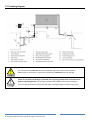
1
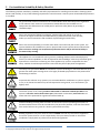
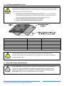
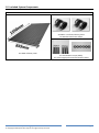
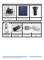
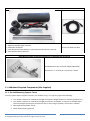
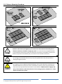
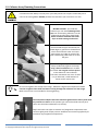
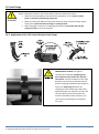
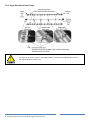
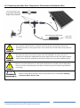
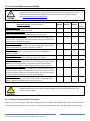
EcoOnline™ - Vertex™ 3.0 Solar Spa Heating System Installation & User Manual – Revised 18/09/2015 Optex Solar Pty. Ltd. www.EcoOnline.com.au email: [email protected] © Copyright 2012 Optex Solar Pty Ltd. All rights strictly reserved. This publication is protected by copyright law and unless otherwise specified is for your personal and non-commercial use only. No part of this publication may be reproduced or distributed by any process, electronic or otherwise, without the specific written permission of Optex Solar Pty Ltd. Trademarks appearing in this manual are the sole property of Optex Solar Pty Ltd or their respective owners. Nothing in this publication shall be construed as granting any express or implied license to use any intellectual property of Optex Solar Pty Ltd otherwise than for personal and non-commercial use only. Optex Solar Pty Ltd must not, to the full extent permitted by law, be held liable for any claim, cost (including legal costs), damage, expense, loss (including fines, penalties, set-offs and consequential loss) or liability arising from the use (or misuse) of any product described in this publication, unless expressly provided otherwise in this publication. Information as well as any products described in this publication are subject to change without notice. Vertex Solar™ Pool & Spa Heating System -- Installation & User Manual © Copyright 2015 Optex Solar Pty Ltd. All rights strictly reserved. Page 1 Contents 1 Key Terms .................................................................................................................................................................. 3 2 Pre-Installation Suitability & Safety Checklist ........................................................................................................... 4 3 Warranties ................................................................................................................................................................ 5 4 System Sizing Guarantee........................................................................................................................................... 5 5 Collector Sizing Guide ............................................................................................................................................... 5 6 Pump Sizing Guide .................................................................................................................................................... 6 7 Spa Chemistry Compatibility Guide .......................................................................................................................... 6 8 Roof Type Compatibility Guide ................................................................................................................................. 7 9 Wind and Climate Considerations............................................................................................................................. 7 10 Included System Components .................................................................................................................................. 8 11 Additional Required Components (Not Supplied) .................................................................................................. 10 12 Required Tools ........................................................................................................................................................ 11 13 Safety When Working at Heights ............................................................................................................................ 12 14 Choosing A Place to Install the Collector Array....................................................................................................... 13 15 Pump and Solar PV Panel Test ................................................................................................................................ 14 16 Collector Array Configurations................................................................................................................................ 15 17 Roof Attachment Options ....................................................................................................................................... 16 18 Collector Mounting Procedure ............................................................................................................................... 19 19 Collector Array Plumbing Connections ................................................................................................................... 20 20 Roof Fixings ............................................................................................................................................................. 21 21 Wind Proofing ......................................................................................................................................................... 24 22 Plumbing Diagram ................................................................................................................................................... 27 23 Installing the Vacuum Beaker Valve & Avoiding Potential U-bend Air Locks ......................................................... 28 24 Protective Bypass & Drain-Down Line .................................................................................................................... 29 25 Suction Line and Pump Mounting Configuration .................................................................................................... 30 26 Solar PV Panel Mounting ........................................................................................................................................ 34 27 Installing the Under-Temperature Thermostat (40°C)............................................................................................ 35 28 Installing the Over-Temperature Thermostat (40°C) .............................................................................................. 36 29 Connecting the Inline Over-Temperature Thermostat and Extension Wire ........................................................... 38 30 Important Installation Check List ............................................................................................................................ 39 31 Operating Instructions ............................................................................................................................................ 39 32 Service and Maintenance Schedule ........................................................................................................................ 41 33 Trouble Shooting ..................................................................................................................................................... 42 Vertex Solar™ Pool & Spa Heating System -- Installation & User Manual © Copyright 2015 Optex Solar Pty Ltd. All rights strictly reserved. Page 2 1 Key Terms This manual was written to follow guidelines and recommendations given in: AS 3634 - 1989 Solar heating systems for swimming pools AS 1170.2 - 2011 (Amend 2 Dec 2012) Structural design actions - Wind actions ‘HAZPAK’ produced by the work-cover authority AS 3000 (2007) Sections 6.3, 6.4 & 6.5 AS 1926.1 & 1926.2 (2007) swimming pool safety - location of safety barrier Please print this manual out and keep it for your reference. Please take the time to read the entire manual before starting any work. Particular attention should be given to text contained in the following key terms. Please note EcoOnline has a strong product safety policy; do not install products without reading safety guidelines in the manual. Please report any product safety issues or near misses to [email protected] no matter how trivial. Indicates a SAFETY issue that is likely to cause injury or death if the user does not follow the instructions. Indicates a SAFETY issue that may cause injury or death if the user does not follow the instructions. Indicates a SAFETY issue that may cause injury or property damage if the user does not follow the instructions Refers to critically important information related to the correct functioning of the system. Refers to useful information for the optimal operation of the system Vertex Solar™ Pool & Spa Heating System -- Installation & User Manual © Copyright 2015 Optex Solar Pty Ltd. All rights strictly reserved. Page 3 2 Pre-Installation Suitability & Safety Checklist The following outlines mandatory suitability and safety requirements for installing a Vertex Solar™ heating system. Please read carefully, if any of the following requirements cannot be meet a Vertex system should NOT be purchased or installed. For ground level collector installations the installer MUST check child safety fence regulations in the relevant state. Under no circumstances should collectors be installed so as to compromise the effectiveness of a child pool or spa fence safety barrier by providing a climbable object. Due to the potential of falling from heights, mounting the solar panels on a roof or structure at heights should only be undertaken by a professional solar panel installer, unless you are accustomed to and confident of performing the work safely. Due to the remote possibility of a water drain down event caused by the Vertex system, this system should not be installed on a pool or spa pool with a mains power electrical devise that does not have a working over temperature protection device and/or will not fail safely in the event of dry running. This appliance is not intended for use by persons (including children) with reduced physical, sensory or mental capabilities, or lack of experience and knowledge, unless they have been given supervision or instruction concerning use of the appliance by a person responsible for their safety. Children should be supervised to ensure that they do not play with the appliance. The safety over-thermostat MUST be installed for systems involving an oversized collector array greater than 100% pool coverage area or for highly insulated spa pools due to the potential for overheating in summer. At present this collector array system is not recommended for installations in cyclonic regions C or D, or on houses situated on top of hills exposed to strong winds, or on second story (or higher) roofs. The Vertex system is for heating outdoor chlorinated or otherwise treated spas ONLY. This system is not to be used to heat indoor spas (chlorinated or otherwise) OR fresh bodies of water due to the potential for Legionaries bacteria build up. Potential flooding resulting from the failure of the Vertex system’s plumbing connections or extreme weather events must be considered by the purchaser/installer, such that flood water from such a failure at any point of a Vertex system will drain safely. Building regulations vary from state to state and MUST override any instructions supplied in the Vertex system manual. It is the responsibility of the purchaser/installer to check that installations comply with any relevant state laws and regulations. Vertex Solar™ Pool & Spa Heating System -- Installation & User Manual © Copyright 2015 Optex Solar Pty Ltd. All rights strictly reserved. Page 4 The Vertex System is not self-priming and requires the installation of the pump outside of but below the waterline of your pool/spa. 3 Warranties EcoOnline™ offers the following Warranties 20 year return to base Warranty on all MOTECH cell solar PV panels 5 year return to base limited Warranty on all Vertex system HDPE collectors 1 year return to base limited Warranty on all Vertex system pumps See EcoOnline.com.au Terms and Conditions page for further details. Customer please note: Collector warranty is VOID if collectors are installed: without a vacuum release valve on the inlet line, or in a manner that prevents collector from fully draining when the pump stops. Such installations will expose the collectors to strong fatiguing positive/negative pressures, and/or stagnant hot chlorinated water on hot days. These situations will have detrimental effects on the collectors which will limit lifetimes and can also result in significant shrinkage of the collectors which would put strain on roof attachments means. Pump warranty is VOID if pumps are installed: 4 without a protective bypass line, or with inappropriately sloped or non air tight suction line, or without the Vertex strainer. System Sizing Guarantee Sizing systems is difficult involving a lot of factors which we could get wrong. Hence in addition to the above Warranties EcoOnline offers a System Sizing Guarantee as follows. If we sized your system (or you use our online calculator) and you took our advice and you aren’t happy with the systems performance (heat output), then you can purchase up to 25% more panels originally supplied by EcoOnline up to two years after your original purchase and we will ship the items free of shipping charges. 5 Collector Sizing Guide An interactive collector sizing calculator can be found on our website at, http://www.EcoOnline.com.au/product-information/solar-pool-heating/sizing-guide Vertex Solar™ Pool & Spa Heating System -- Installation & User Manual © Copyright 2015 Optex Solar Pty Ltd. All rights strictly reserved. Page 5 6 Pump Sizing Guide An interactive pump sizing calculator can be found on our website at, http://www.EcoOnline.com.au/product-information/solar-pool-heating/sizing-guide When installing this system it is imperative to check whether the pump will provide a sufficient water flow rate at the pump height of the installation. 7 Spa Chemistry Compatibility Guide This system is not compatible with bromide chlorination, hydrochloric acid use and/or acidic pool/spa water (pH less than 7.2). Sodium Carbonate must be added to protect the system from acidic pH (<7). pH should be maintained between 7.2-7.8 for maximum system longevity. If absolutely required Sodium Bisulphate acid can be used to keep the pH down. Incompatible Chemistries ✘ Bromide Based Chlorination ✘ Hydrochloric Acid ✘ Acidic Water (pH less than 7.2) Alternatives Chemistry ✔ Any other Chlorination or Sanitation ✔ Sodium Bisulphate Acid ✔ Water pH greater than 7.6 Vertex Solar™ Pool & Spa Heating System -- Installation & User Manual © Copyright 2015 Optex Solar Pty Ltd. All rights strictly reserved. Page 6 8 Roof Type Compatibility Guide The average air gap distance between the mounted collector and roof structure has a strong influence on wind loadings. If panels are to be installed on a roof then the following should be observed to limit wind uplift potential. 1) Installed panels should lay flat touching the roof structure. It is recommend the air gap distance between the bottom of the installed collector and the valley points of the roof corrugations should be no greater than approximately 25mm. 2) Panels should have adequate clearance from roof edges. 3) Panels on roofs should not be mounted on tilt frames. Roof Type Standard Corrugated Iron roof (Custom Orb) Relatively Flat Tile roof Spandek Iron roof Modulated Tile roof Trimdek Iron roof Klip-lok Iron roof Flatdek Iron roof Air Gap Distance 17mm Less than 25mm 24mm Greater than 25mm 29mm 43mm 45mm Recommendation Okay Okay Okay Region A Only Region A Only Not Recommended Not Recommended Panels installed above the roof structure with 50mm or greater underneath air gaps experience much higher wind loadings and are now subject to the Australian wind loading standard AS/NZD 1170.2. 9 Wind and Climate Considerations It is the responsibility of the installer to consider wind loading factors, see “wind proofing” section below. If the installation site is within strong wind speed areas then the extra stainless steel guide line must be installed across each row with the in-between panel anchor points. Do not assume supplied components are sufficient. Vertex Solar™ Pool & Spa Heating System -- Installation & User Manual © Copyright 2015 Optex Solar Pty Ltd. All rights strictly reserved. Page 7 10 Included System Components Panel Kit 2 × 40mm reinforced silicon joiners 4 × Stainless steel hose clamps 1 × HDPE collector panel 6 × 316 stainless straps (black) 1 × 25cm length perforated 316 stainless band Vertex Solar™ Pool & Spa Heating System -- Installation & User Manual © Copyright 2015 Optex Solar Pty Ltd. All rights strictly reserved. Page 8 12V Solar Pump Kit 1 × 40W or 60W 12V Solar pump, with pump enclosure and electrical connector. 1 × 40W or 60W Solar panel with PVC wire, connector and undertemperature thermostat (if supplied) 1 × PVC 316SS mesh Strainer Vertex Base Plumbing Kit Components 1 × Vacuum (and positive pressure) air release valve 2 × 40mm hose barb to 25/32mm PVC glue socket/take off 1 × PVC clear bypass line kit - includes 3mm constriction Vertex Solar™ Pool & Spa Heating System -- Installation & User Manual © Copyright 2015 Optex Solar Pty Ltd. All rights strictly reserved. 1 × 20mm PVC Nonreturn valve (non-spring loaded) Page 9 Safety Over-Temperature Thermostat Kit 2× 1× 1× 1× 3× 25mm ID Armaflex pipe insulation 60mm ID Armaflex pipe insulation Aluminium U-channel Twin 40°C thermostats with 2m cord and positive disconnect connector PVC coated stainless cable ties 1 × 5m PVC Extension Wire Roof Mounting (Solar roof hook supplied only if requested and purchased) 1 × 304 Stainless solar roof hook (height adjustable) Dimensions: A = 47.5mm,B = 117.5mm,C = 60mm 11 Additional Required Components (Not Supplied) 11.1 Ground Mounting Support Frame You may need to build a support frame for your collector array, if so you may require the following: Two 70mm x 35mm 1.3m treated pine length per collector (lengths depend on mounting preferences) Two 70mm x 35mm 1.1m treated pine length per collector. (Preferably, if transport is available these horizontal lengths should span the collector array or be as long as possible, see section 6.1 below) 60mm galvanized timber screws. Black outdoor paint (optional) Vertex Solar™ Pool & Spa Heating System -- Installation & User Manual © Copyright 2015 Optex Solar Pty Ltd. All rights strictly reserved. Page 10 11.2 Roof Mounting If installing the panels on a roof you will also require the following extra items. 32mm x 32mm x 3mm Aluminium angle 4mm stainless steel cable & four cable ties per row These are available in any plumbing store. The aluminium angle is available from Capral Ltd. or Ullrich Aluminium Pty. Ltd. 11.3 Additional Plumbing Components You also require some of the following extra items depending on your system. These should be available in any spa/swimming pool supplier. PVC 25mm piping PVC 20mm piping PVC 20mm barrel union join 20mm “Spa flex” flexible PVC hose (recommend for frost prone areas) Other 20mm or 25mm PVC plumbing bits We recommend AS 1477 compliant PVC 20mm piping with PN9 pressure rating or greater and matching PVC fittings be used for all plumbing. We also recommend 20mm “spa flex” flexible PVC hose for suction line pump plumbing. (Do not use any irrigation fittings as they are not compatible with chlorinated water). 12 Required Tools - Battery powered hand drill with 8mm Hex socket - Clear silicon - PVC glue (Green pressure) - Soldering iron - Screwdriver with 8mm socket fitting - Hack saw (metal blade to reduce PVC filing size) - Level - 3mm drill bit Vertex Solar™ Pool & Spa Heating System -- Installation & User Manual © Copyright 2015 Optex Solar Pty Ltd. All rights strictly reserved. Page 11 13 Safety When Working at Heights WHEN WORKING AT HEIGHTS - SAFETY COMES FIRST. A person can easily fall off a ladder or roof and be seriously injured. For installations on a roof pitch greater than 22° and/or a double story house we strongly recommend a highly competent professional installer install your solar collector array. The installer MUST use an appropriate safety harness. The installer should always take the necessary safety precautions: Choose an appropriate day: cool, dry, calm and partly cloudy. Plan out your install: make sure you have all required components, tools and have plenty of allocated time. Only work at heights when you are well rested and alert. Never work alone, always work with at least one other person. Always use a safety harness or fall arrest system attached to appropriate roof anchor points. Wear clothes that fit well but that do not restrict movement. Use proper non-slip shoes. Use sunscreen. 13.1 Ladder Safety The chance of a falling from a ladder should never be underestimated. Use only solid industrial grade ladders in good repair that have been checked for faults. Note: even a small unexpected movement of the ladder, such as a small slip, can cause loss of balance and result in a fall. The ladder should be placed on solid ground and should ALWAYS be securely anchored at the base and secured at the top to prevent slipping. Solar panels should not be mounted in windy or gusty conditions; a panel can easily be caught in the wind and cause a loss of balance and result in a fall. Vertex Solar™ Pool & Spa Heating System -- Installation & User Manual © Copyright 2015 Optex Solar Pty Ltd. All rights strictly reserved. Page 12 14 Choosing A Place to Install the Collector Array When choosing a location for your collector array you should consider the following in order of importance: 1. Shading - the collectors should receive no shading between the hours 10am to 4pm. 2. Wind - the collector array should be mounted in a relatively sheltered location or with appropriate wind proofing. 3. Direction - collectors should face NNW for maximum heat collection, however acceptable directions face between NE to W only. Systems facing other directions will have significantly impaired performance. 4. Distant to pool/spa - collectors should be as close as possible to your spa (or pool), or have insulated lines. 5. Mounting elevation - flatter elevations (< 45°) collect more heat in the summer while installations closer to vertical (> 45°) produce more heat during spring/autumn. For ground mounted arrays, under no circumstances should a collector array be mounted in anyway so as to compromise the effectiveness of a pool or spa Child Safety Barrier. The figure to the left shows an example of a Child Safety Barrier marked with a dashed line. A collector array should not be mounted near the Child Safety Barrier both on the inside and outside of the Pool Area unless proper clearances are observed. Consult your Local Government, The Building Commission or SPASA for details regarding pool safety barriers in your state. Please keep up to date with regulations as they change over time. For more information see, AUSTRALIAN STANDARDS 1926.1 2007 AND 1926.2 2007 FOR POOL SAFETY BARRIERS. Do not install the collectors leaning against the outside of a Child Safety Barrier so as to create a climbable object for children to access the pool or spa. Collectors installed inside the pool area in front of a boundary fence must be offset away from the boundary fence with the proper clearance from the top of the fence so as not to provide a foothold for a child climbing into the pool area. Do not install the collectors too close to the inside of a Child Safety Barrier so as to provide foot or handholds from the outside of the barrier. For spa pools and above ground pools do not lean the collector array against the side of the spa or pool so as to create a ramp or climbable object. Vertex Solar™ Pool & Spa Heating System -- Installation & User Manual © Copyright 2015 Optex Solar Pty Ltd. All rights strictly reserved. Page 13 15 Pump and Solar PV Panel Test During the following test DO NOT allow the pump to run completely dry as this may damage the pump. 1) On a sunny day, pour water into the pumps inlet and block the pumps outlet. 2) If you have a panel with an under temperature thermostat you will need to bring it up to temperature with a hair dryer. 3) Situate the solar PV panel away from sunlight. Connect the panel to the pump using the electrical connector. Pick up the solar panel and angle toward the sun, the pump should start in 3-4 secs. 4) Check to see that the pump is working for a few seconds. 5) Familiarize yourself with the noise characteristics of a fully primed and partly primed pump. You will need to diagnose potential air locks in your pump. (Note, pump can run partly primed for a few seconds without damage.) 15.1 What if the Pump Won’t Start? 1) Check that there is sufficient sun and that no cell of the panel is shaded. 2) Check that the under-temperature thermostat is ON and that the panel is producing power (if a multimeter is not available, insert an old 50W halogen globe into the panels electrical connect – do not do this is full sun, angle panel to sun to reduce power). 3) Check that the wires in the connector aren’t twisted internally and the positive and negative connections line up. 4) Check the polarity in the solar panel junction box, see section 26. 5) If it still won’t start please contact us at [email protected] for a replacement pump. Sometimes an air locked mode can arise in the pump when a sufficiently large air bubble makes its way into the inlet of a working pump. In this state water cannot be pushed higher, nor can the column of water above the pump make its way back through the spinning rotor. In this mode the pump can overheat and burn out within 15mins. Vertex Solar™ Pool & Spa Heating System -- Installation & User Manual © Copyright 2015 Optex Solar Pty Ltd. All rights strictly reserved. Page 14 16 Collector Array Configurations To make sure all air bubbles are evacuated upon filling, collectors MUST be installed with a minimum recommended pitch of 5˚. Also ideally the top header pipe should have a 1 or 2° upward slope toward the top outlet return, such that the top outlet return corner of the collector array at the highest point. 16.1 Array Configurations Not Recommend Vertex Solar™ Pool & Spa Heating System -- Installation & User Manual © Copyright 2015 Optex Solar Pty Ltd. All rights strictly reserved. Page 15 17 Roof Attachment Options Note the high thermal contraction and natural relaxation of HDPE: Collectors will contact (in length) by up to 10mm over time and 12mm thermally across temperature extremes. Hence any fixing means must account for an ultimate contraction of 22mm in length per panel. Key design principles when choosing a roof mounting means: 1) Consider the high thermal contraction of HDPE 2) Panels should be as low down on the roof as possible to prevent the wind from catching the underside of panels. 3) The stainless steel straps should not be used to support loads, only as security against excessive wind speeds. 17.1 Tile Roof Mounting Frame For tile roofs we recommend using a minimum roof hook spacing of 600mm in the top and bottom row. Depending on your wind loading (see “Wind Proofing” section), angle of install and the dead weight of the collectors, you may require a higher density of roof hooks and/or a stronger Aluminium L-angle, if unsure please seek advice. Vertex Solar™ Pool & Spa Heating System -- Installation & User Manual © Copyright 2015 Optex Solar Pty Ltd. All rights strictly reserved. Page 16 17.2 Corrugated Metal Roof Mounting Frame For metal roofs we recommend using a minimum roof hook spacing of 600mm in the top and bottom row. Depending on your wind loading (see “Wind Proofing” section), angle of install and the dead weight of the collectors, you may require a higher density of roof hooks and/or a stronger Aluminium L-angle, if unsure please seek advice. Vertex Solar™ Pool & Spa Heating System -- Installation & User Manual © Copyright 2015 Optex Solar Pty Ltd. All rights strictly reserved. Page 17 Vertex Solar™ Pool & Spa Heating System -- Installation & User Manual © Copyright 2015 Optex Solar Pty Ltd. All rights strictly reserved. Page 18 18 Collector Mounting Procedure Collectors will contact (in length) by up to 10mm over time and 12mm thermally for an ultimate contraction of 22mm in length per panel. For a two row array strapped between a top and bottom aluminium rail the total ultimate contraction is then 44mm. The top and bottom strap must have sufficient play to account for this ultimate contraction. It is strongly recommended that the top straps be applied while cool pool/spa water is flowing through the panels. The collectors can be walked on without damage. For tile roofs with solar roof hook care should be taken not to step on or near a roof hook as you may crack a tile. Take extreme care to use non-slip shoes and never walk on wet collectors. HDPE material is slippery and waxy. If the collectors need to be walked on for mounting purposes, ALWAYS use a safety harness and fall arrest system. Vertex Solar™ Pool & Spa Heating System -- Installation & User Manual © Copyright 2015 Optex Solar Pty Ltd. All rights strictly reserved. Page 19 19 Collector Array Plumbing Connections Laceration hazard: Always cut away from your body and ensure no parts of the body are in front of the cutting blade. DO NOT perform this task when you are tired or in a rush. BEFORE CUTTING - put aside two collectors per row with undamaged end caps. For all remaining collectors cut the single end cap off using a sharp blade. Plastic should be softened with a hair dryer to make cutting much easier. Check all collector pipe connections for raised edges or grooves on the weld lines which could channel water and cause leaks. Shave any edges or grooves flat with a blade being careful not to cut into the pipe. After inserting silicon joiners and hose clamps moderately tighten the clamps using a hand screwdriver with an 8mm hex socket. Do not glue in silicon joiners as this allows for some collector contraction movement over time. If there is a pin hole leak, a small amount of silicon can be used to seal. Do not over tighten hose clamp at this stage - HDPE has a high thermal expansion. You’ll need to re-tighten these with cool water running through the collectors at a later stage. Make sure all nuts are accessible for future tightening. The inlet/outlet adapter PVC barbs should be glued into the silicon joiner with any neutral cure silicon. A flat spatula type surface should be used to push silicon into the barbs indentations (as shown). Why? PVC barbs can soften at extreme roof stagnation temperatures and contract sightly with clamps pressure. HDPE will not contract significantly at maximum roof stagnation temperatures. Vertex Solar™ Pool & Spa Heating System -- Installation & User Manual © Copyright 2015 Optex Solar Pty Ltd. All rights strictly reserved. Page 20 20 Roof Fixings When working with power or hand tools always follow the safety instructions. Wear the recommended personal protective equipment, such as gloves, safety glasses, respiratory and hearing projection. Make sure electrical cables are kept away from any water and from foreign objects which pose a potential cable severing or crushing hazard. When using glues, solvents or sealing agents make sure you know and seek the proper first aid in case of an accident. 20.1 Application of the PVC Coated Stainless Steel Straps IMPORTANT: DO NOT over tighten stainless steel strapping. Strapping must have sufficient play to allow for collector contraction. For the installation of two rows between two aluminium channels top and bottom strapping should be loose enough to insert your little finger between the strapping and the header pipe. Why? Over tightened straps can experience tension and continual flexing of the metal due to the thermal contraction of the collectors. This can result in metal fatigue of roof fixings over time. Vertex Solar™ Pool & Spa Heating System -- Installation & User Manual © Copyright 2015 Optex Solar Pty Ltd. All rights strictly reserved. Page 21 20.2 Single Row Metal Roof Fixings For single or multi-row arrays in wind regions B & C, aluminium L-angle MUST be run for the top and bottom of each row. Vertex Solar™ Pool & Spa Heating System -- Installation & User Manual © Copyright 2015 Optex Solar Pty Ltd. All rights strictly reserved. Page 22 20.3 Single Row Tile Roof Fixings For single or multi-row arrays in wind regions B, aluminium L-angle MUST be run for the top and bottom of each row. 20.4 Perforated Band Under-Tile Anchor Point (For Region B or Two row arrays) Vertex Solar™ Pool & Spa Heating System -- Installation & User Manual © Copyright 2015 Optex Solar Pty Ltd. All rights strictly reserved. Page 23 21 Wind Proofing Note, roof installation of these panels in Wind Region D is not recommended. This section provides general advice on wind loadings. If you have any doubt about your wind loadings please contact [email protected] 21.1 Ultimate Peak Wind Loadings per Panel The following Tables specify the ultimate peak uplift any single panel can experience in a 1 in 500 year extreme storm or cyclone event according to Australian Standard 1170.2 - 2011 (Amend 2 Dec 2012). These tables assume: 1) 2) 3) 4) Panels are mounted on (touching) the roof structure - or no more that 20mm off the roof surface Panels are situated away from a roof edge or corner Installation is on a first story roof Shortest side length of the building is more than twice the average building height (i.e. flat building) If your installation falls outside of these assumptions please contact [email protected] for alternative loadings. Ultimate Peak Uplift Loadings Per Panel in Wind Region A (Kg) Region A Terrain Category 1 Terrain Category 2 Terrain Category 2.5 Terrain Category 3 < 10˚ Roof Pitch 12.5˚ Roof Pitch 15˚ Roof Pitch 17.5˚ Roof Pitch > 20˚ Roof Pitch 120 Kg 110 Kg 95 Kg 90 Kg 80 Kg 100 Kg 90 Kg 80 Kg 70 Kg 65 Kg 90 Kg 80 Kg 70 Kg 65 Kg 60 Kg 85 Kg 75 Kg 65 Kg 60 Kg 55 Kg Ultimate Peak Uplift Loadings Per Panel in Wind Region B (Kg) Region B Terrain Category 1 Terrain Category 2 Terrain Category 2.5 Terrain Category 3 < 10˚ Roof Pitch 12.5˚ Roof Pitch 15˚ Roof Pitch 17.5˚ Roof Pitch > 20˚ Roof Pitch 195 Kg 175 Kg 150 Kg 140 Kg 130 Kg 160 Kg 145 Kg 125 Kg 115 Kg 105 Kg 150 Kg 130 Kg 115 Kg 105 Kg 100 Kg 135 Kg 120 Kg 105 Kg 95 Kg 90 Kg Ultimate Peak Uplift Loadings Per Panel in Wind Region C (Kg) Region C Terrain Category 1 Terrain Category 2 Terrain Category 2.5 Terrain Category 3 < 10˚ Roof Pitch 12.5˚ Roof Pitch 15˚ Roof Pitch 17.5˚ Roof Pitch > 20˚ Roof Pitch 290 Kg 255 Kg 225 Kg 210 Kg 190 Kg 240 Kg 215 Kg 185 Kg 170 Kg 160 Kg 220 Kg 195 Kg 170 Kg 155 Kg 145 Kg 200 Kg 175 Kg 155 Kg 145 Kg 130 Kg As an example if you are in Wind Region B and Terrain Category 3 and have a roof pitch 12.5˚ then any single panel in your collector system could experience momentary peak uplifts of ~120Kg per panel. You should make sure your Vertex Solar™ Pool & Spa Heating System -- Installation & User Manual © Copyright 2015 Optex Solar Pty Ltd. All rights strictly reserved. Page 24 panels and fixing components can withstand your relevant loadings. See below for Terrain Category and Wind Region definitions. Note: Installations involving a second story roof or higher, or houses on hills, or panels mounted 50mm or greater above the roof structure have higher potential wind loadings. Please contact [email protected] for ultimate wind loadings based on your details. 21.2 Frequency of Extra Fixings for Different Regions For ultimate wind loadings (see Tables above): Less than 70Kg per panel Greater than 70Kg per panel Greater than 120kg per panel Extra Fixings Required Stainless guide line is not required (but still recommended) Stainless guide line is required across each row Stainless guide line is required with in between anchor points 21.3 Wind Region Definitions Coastal region boundaries are smooth lines set in from a smoothed coastline by 50km, 100km or 150km lines. Vertex Solar™ Pool & Spa Heating System -- Installation & User Manual © Copyright 2015 Optex Solar Pty Ltd. All rights strictly reserved. Page 25 21.4 Terrain Category Definitions Terrain Category 1: Open terrain few obstructions. Example flat, treeless, poorly grassed plains. Terrain Category 2: Open terrain with scattered obstructions having heights from 1 .5m to 5m, with at least two building type obstructions per hectare. Example farmland and cleared subdivisions with isolated trees. Terrain Category 2.5: Averaged intermediate between Terrain Category 2 and Terrain Category 3 Terrain Category 3: Numerous closely spaced building obstructions having heights from 3m to 10m with at least 10 house-size obstructions per hectare. Example fully developed suburb or light industrial estates. 21.5 Roof Edge Exclusions Zones Note: Collector installations within a roof edge exclusion zone require 2 X the fixing strength in that local area. Collector installations within a roof corner exclusion zone require 3 X the fixing strength in that local area. Vertex Solar™ Pool & Spa Heating System -- Installation & User Manual © Copyright 2015 Optex Solar Pty Ltd. All rights strictly reserved. Page 26 22 Plumbing Diagram The installation of at least two Australian Standard approved suction outlet adapters, 600mm apart connected by a T-piece PVC plumbing is mandated for pools and spas. Make sure all PVC saw shavings are cleared prior to gluing and that lines are flushed clean before connecting pumps. PVC shavings can block the impeller of the pump resulting in burnout. We recommend a metal hack saw when cutting PVC pipe to reduce shaving size. Vertex Solar™ Pool & Spa Heating System -- Installation & User Manual © Copyright 2015 Optex Solar Pty Ltd. All rights strictly reserved. Page 27 23 Installing the Vacuum Beaker Valve & Avoiding Potential U-bend Air Locks There should be no U-bends in the return line or suction line – in other words water in the return line should never be forced to travel uphill while conversely, when the pump is running water in the suction line should never travel downhill. If any part of the return line plumbing or return outlet port is installed far below the water line (greater than 0.5meters) then an extra Vertex vacuum beaker valve should be installed at the water level to minimize the extra pump height created. The Vacuum Breaker valve should face vertically upward. Unscrew black air intake nozzle. Vertex Solar™ Pool & Spa Heating System -- Installation & User Manual © Copyright 2015 Optex Solar Pty Ltd. All rights strictly reserved. Page 28 24 Protective Bypass & Drain-Down Line A protective bypass line (15) with 3mm constriction must be installed for the system. The bypass line should be placed at not more than 1 to 2m pump height. Why? Solar power is an intermittent power supply. In part sun the pump may not be supplied with sufficient power to reach the pump height. Without a bypass line this will result in a running pump with no cooling water flow which can overheat a pump. Secondly, with a non-return valve in place the by-pass allows the system to drain down. 24.1 Installation The drain tube should be installed on the supply and return solar lines leading up to the roof approximately 1-2 metres from water level. To install, drill into the PVC pipe using an 8.5mm drill. Note: PVC plastic should be preheated to 40˚C using a heat gun or it may split when drilling. Insert the rubber grommet into the hole tapered end first. Vertex Solar™ Pool & Spa Heating System -- Installation & User Manual © Copyright 2015 Optex Solar Pty Ltd. All rights strictly reserved. Page 29 25 Suction Line and Pump Mounting Configuration The pump should be supported such that there is a minimum amount of stress on the pump’s inlet and outlet piping. The pump should not be suspended in the air by its inlets and outlets without support. Use only the supplied non-spring non-return valve (or flap valve). Why? A small pump will have trouble pushing against a spring loaded valve adding to the pump height. This will reduce flow and can overheat and damage the pump. The pump should be installed in a way which allows easy access dismantling for maintenance. Connection of the pipe work to the pump should permit the removal of the pump without the need to cut the pipe work. Vertex Solar™ Pool & Spa Heating System -- Installation & User Manual © Copyright 2015 Optex Solar Pty Ltd. All rights strictly reserved. Page 30 25.1 Allowed Suction Pipe Configurations All piping from the suction points to the collector array MUST be sloped upwards. There can be no air trap sites in the suction line. Why? Small air bubbles can accumulate in the suction line when the system drains down through the suction line. Air pockets in the suction line can release large air bubbles which can air lock a pump no matter how far the pump is below the water line. This leads to zero flow, overheating and pump failure. All suction line connections must be made with air tight PVC glue sockets. Pink Teflon tape with silicon grease should be applied to any threaded connections on the suction line and pump connections. Vertex Solar™ Pool & Spa Heating System -- Installation & User Manual © Copyright 2015 Optex Solar Pty Ltd. All rights strictly reserved. Page 31 25.2 Allowed Mounted Pump Orientations The pump must be mounted as shown above, so that it automatically flood primes without needing to force water through. See “Pump Enclosure Assembly” section to understand the internal orientation of the pump within the enclosure. 25.3 Allowed Mounted Strainer Orientations The strainer must be mounted so that it automatically flood primes without needing to force water through. Vertex Solar™ Pool & Spa Heating System -- Installation & User Manual © Copyright 2015 Optex Solar Pty Ltd. All rights strictly reserved. Page 32 25.4 Pump Enclosure Assembly Never carry the pump by the electric supply cable as this may damage the pump and make it unsafe. The pump can be fixed in place by running a perforated metal band around the plastic base and screwing to a wooden frame. The stainless steel hose clamps on the enclosure should be tightened AFTER the enclosure and piping is fixed in place. This is to release any stress on the pumps inlet/outlets connections. Vertex Solar™ Pool & Spa Heating System -- Installation & User Manual © Copyright 2015 Optex Solar Pty Ltd. All rights strictly reserved. Page 33 26 Solar PV Panel Mounting Before mounting the panel, you will need to thread the PVC wire into the junction box and solder the brown (or red) wire to the right-hand side, or positive terminal and the blue (or black) wire to the left hand side, or negative terminal. (Check for the + and – markers in the junction box). We highly recommend a plug (made from cut wire) be used to weatherproof seal the other wire hole. Replace junction box cover. Wires must be soldered to the terminal – if a loose or corroded connection develops over time it can create a resistive load which could melt or burn surrounding material, or cause a fire. An aluminium angle should be attached to the back of the solar panel for mounting purposes using the back mounting holes. If your system came with an under temperature thermostat you will need to drill a hole in the thermostat mount and bolt to the solar panel frame such that the under-temperature thermostat with insulation fits into the channel. Important: Wind loading should be considered. 26.1 Solar PV Panel Location For ease of maintenance, short wire issues and a reduced chance of lighting strike - we highly recommend that the solar panel is mounted as close to the ground as possible without running into shading issues. Generally speaking the PV panel should be mounted at near the same pitch and azimuth (compass direction) as the collector array. However, for west facing collector installations it is preferable that the PV panel face NW. Your solar panel and under-temperature thermostat form the pumps control system, they should be oriented with Vertex Solar™ Pool & Spa Heating System -- Installation & User Manual © Copyright 2015 Optex Solar Pty Ltd. All rights strictly reserved. Page 34 respect to the main collector array such that the system comes on at the right time and switches off at the right time for maximum system efficiency. 26.2 Extending the Electrical Wires The 5meter extension lead can be used to extend any of the three leads, i.e. the 1m pump lead, the 2m overtemperature lead or the 5m solar lead. Please note, we do not recommend further extensions as this will create too high a voltage drop. If a further extension is absolutely necessary we recommend you not use the 5m extension lead. Instead splice in a much higher gauge wire wherever required. You will need to purchase an appropriate splice kit at your local electrical supplier. If unsure we strongly recommend a qualified electrician splice wires together, as bad electrical connections can form a fire hazard. 27 Installing the Under-Temperature Thermostat (40°C) You may have been supplied with a 40°C under temperature thermostat to prevent the pump from turning on during cold but sunny conditions. This undertemperature should be attached to the side of the solar PV panel using the components provided. The thermostat will turn on when its internals (which are representative of the internals of the polymer panel) come to temperature and turn off below a certain temperature. Thermostat Specifications 40°C Normally Open (disconnected) Closes at 45°C ± 3°C Resets at 35°C ± 3°C 27.1 Cooling Issues on Spring Days: Adjusting the Set Under-temperature Thermostat Time of day biasing: the thermostat should be mounted so that its flat face is rotated by about ~ 20° toward East from the arrays mounting orientation to help lower the activation criteria during mid mornings after the spa pool temperatures have cooled overnight. This rotation also helps to bias the system toward higher temperature in the evenings when the spa pools temperatures are higher. Insulation biasing: If the thermostat switches on too readily on cool days (and/or you run your spa at a high preferred temperature) then the thermostat should be installed without the silicon insulation. Insulation biasing: If the thermostat does not switch on readily enough (and/or you run your spa at a lower temperature) then the thermostat should be installed with the silicon insulation. Vertex Solar™ Pool & Spa Heating System -- Installation & User Manual © Copyright 2015 Optex Solar Pty Ltd. All rights strictly reserved. Page 35 28 Installing the Over-Temperature Thermostat (40°C) Important: If the area of your collector array is oversized for your pool/spa and/or you have a highly insulated pool/spa pool - you will require a safety thermostat to prevent the potential overheating of your pool/spa. The thermostat assembly should always be installed on the higher temperature OUTLET (RETURN) SIDE of the collector array. General Spa Pool Safety Notice: Prolonged bathing in hot water may increase a person’s normal core body temperature of 37°C, which could result in hyperthermia. Persons affected by hyperthermia may experience, weakness, fainting, nausea, drowsiness, and muscle cramps - as a result, they may experience a failure to perceive the impending danger of prolonged immersion and the need to exit the spa pool, and/or they may be physically unable to exit the spa pool. Using an accurate thermometer the spa pool owner should always check water temperatures do not exceed 40°C before allowing people to enter the spa pool. A water temperature of 38°C or lower is recommended for young children or pregnant women. Never use alcohol, drugs, or medication before entering a spa pool. As a precautious when working around a spa bath we recommend all mains power be switched off. The Vertex system is extra low voltage safe, however if you have any doubts about your ability to carry out electrical work on the Vertex system we recommend your wiring is installed and serviced by a qualified electrician. 1) Vertex Solar™ Pool & Spa Heating System -- Installation & User Manual © Copyright 2015 Optex Solar Pty Ltd. All rights strictly reserved. Page 36 2) 3) Over-temperature thermostat assembly MUST be installed in a sheltered location away from rain and sun expose and in such a way that any water droplet condensation on pipes or wires cannot run inside the assembly. Adequate insulation of the Aluminium U-channel is required, otherwise the exposure of the U-channel to cooler external air may prevent the U-channel and hence the face of the thermostat from reaching the cut-off temperature. The supplied 40°C thermostat (with secondary failsafe) will disconnect the pump(s) positive wire if the temperature of the water in the return line is about 40 to 42°C. The temperature differential across the solar collector array will mean that your spa temperature should be at or below 40°C during trigger. 28.1 Adjusting the Spa Temperature If you require a lower spa temperature, we recommend you use ball valve (1) to constrict flow slightly. This will increase the temperature differential across the collector array and turn the system OFF faster. Note, if you are going to be using this method we recommend you drill a 3mm hole in ball valve (1) in case you accidently close this valve fully, as this could block all flow and burn out your pump. Vertex Solar™ Pool & Spa Heating System -- Installation & User Manual © Copyright 2015 Optex Solar Pty Ltd. All rights strictly reserved. Page 37 29 Connecting the Inline Over-Temperature Thermostat and Extension Wire The connectors should not be in a position such that they are continuously exposed to splashing spa water or rain ingress which can run down the cord and make its way inside the connector. The electrical system of the Vertex system cannot be modified in any way, such as for example the introduction of any alternate power supply other than the solar panel supplied. Vertex system electrical components cannot be used as part of any other modified system. Never run a 12-24V cable near or in the same compartment or conduit as other 240V cables due to the chance of mistaking the two cables at some later point in time during installation or servicing. Before turning ON the pump for the first time please refer to section 31.1 Switching the System ON for the First Time. Vertex Solar™ Pool & Spa Heating System -- Installation & User Manual © Copyright 2015 Optex Solar Pty Ltd. All rights strictly reserved. Page 38 30 Important Installation Check List Your installation must have the following elements. The top header pipe was installed with a 1 to 2° slope toward the outlet. Aluminium channel was laid top and bottom of the collector array as shown in the manual. Ultimate uplift wind loadings were considered and panels secured appropriately. The stainless steel strapping was installed with sufficient play to allow for collector contraction. The roof edge exclusion zone was observed. A hot spot check was performed. All collectors are cool during full sun exposure (top of panels may be warmer). The PV panel is mounted with at least 2cm clearance from its mounting surface for underside ventilation. The collector array faces anywhere from West to North East. A vacuum release valve was installed on the roof near the collector inlet line. The outlet is submersed in the pool/spa. A minimum of stress is placed on the pumps inlet/outlet pipe connections. The pump and enclosure is well supported (pump does not hang by the inlet/outlet connections). The pump and filter were installed with allowed orientations only (so as not to create air traps). All suction line prior to the pump is air tight and slopes up toward to the pump with no air traps. The over-temperature thermostat was installed and tested. The thermostat U-channel and thermostat itself is well insulated from the surroundings. PVC plumbing lines were laid at such an angle so that all water drains from them for frost proofing. The possibility of a drain down event caused by a failure in the Vertex plumbing lines was considered. A protective bypass line was installed, no more than 1-2 meters pump height with a minimum 3mm bypass passage. 31 Operating Instructions The system strainer should be cleaned regularly depending on spa use. For pools larger than 15m2 we recommend that the filter pump run at least a short period in the evening so as to help mix the warm water deeper into the pool otherwise the top layer of warm water will cool excessively at night. We strongly recommend the system be switched off during pool/spa use or when you go on holidays. The system can be switched on after use, making sure people are away from the outlet and that the pump is still primed. 31.1 Switching the System ON for the First Time We recommend you wait till a sunny day and follow this procedure: 1. After the under-temperature thermostat has turned ON, connect the pump which will start in 3secs. Listen to the pump start - after an initial purge of air the pump should run smooth. 2. After 5 mins running disconnect the pump and let the system drain down. Vertex Solar™ Pool & Spa Heating System -- Installation & User Manual © Copyright 2015 Optex Solar Pty Ltd. All rights strictly reserved. Page 39 3. After 30 mins worth of draining reconnect the system and check that the pump starts smoothly. If the pump does not start perfectly smoothly during this second start up, then air is getting into the pump and/or suction line during drain down. Check for air leaks or air traps, see above section on allowed suction line angles. 31.2 Check for Balanced Water Flow through All Collectors 1. 2. With the sun shining on the collectors and the pump operational, run your hand over every part of each collector. Collectors should be cool to the touch while the top of each collector could be slightly warmer. Hot spots indicate that there is no water flow through this part of the collector. To eliminate hot spots make sure the top header pipe of the entire collector array runs straight and that it has a slight slope (minimum 2°) with the outlet having the highest point. The inclination of the array may need to be increased. If there is no sun available to perform this test, do not leave the pump connected. Do not let the system run for the first time unattended. During full sun operation the outlet water flow should be strong with a temperature no greater than about 5-7°C that of the inlet. 31.3 Legionaries Risk The Vertex system must be switched off 1 hour before spa use. Disinfectant should be introduced and the filter pump run for at least 1 hour before spa pool use. Always follow disinfection advice supplied by your spa pool manufacture. Vertex Solar™ Pool & Spa Heating System -- Installation & User Manual © Copyright 2015 Optex Solar Pty Ltd. All rights strictly reserved. Page 40 32 Service and Maintenance Schedule Important: before carrying out any system maintenance you MUST check for any manual and or technical service bulletin updates and download the latest installation manual from www.EcoOnline.com.au/downloads Maintenance Issue - Service Procedure Barb Plastic Relaxing - All the stainless steel hose clamps may need retightening as plastic relaxes overtime. Corroded or Fatigued Wiring – Wiring, solder connections and wire fixings should be checked for damage and/or corrosion signs. Silicon Joiner Chemical Attack – Disconnect a single silicon joiner, dry and check that the water exposed inside section has not turned grey or become unfirm to the touch. This would indicate chemical attack from a pH lower than 7. Replace as needed. Stainless Strap Fatigue - Inspect all stainless steel fixing straps for wear of PVC coating around the sharp Aluminium L-angle edge, which would indicate fatigue working of straps. Replace as needed. Mounting Frame - The integrity of the collector mounting frame and wind proofing components should be checked for any degradation. Replace as needed. Plumbing Degradation – Plumbing lines and fittings should be checked for signs of UV and/or chemical damage. Replace as needed. Vacuum Release Valve – The vacuum release valve is a critical system component. It should be checked that it is functioning correctly and that collectors are draining properly. The collector’s facets around weld points should never appear collapsed (concave) by negative pressure. Collector Plastic Contraction – Collectors can relax and contract by 10mm in length over the initial first few years. It should be checked that the stainless steel straps or fixings have not become too tight as a result. If required straps will need to be loosened slightly. This check should be carried out when the collectors are cool (water flowing). Debris Accumulation – Inspect the inner of the collectors. Depending on conditions collectors may need to be flushed with a suitable cleaning agent for debris accumulation after many years of use. 1st Month 1st Quarter X Annual Checks After 5 Years X X X X X X X X X X X Fatigued, weathered, loose and/or corroded wiring or electrical connections poses a fire risk even at low voltage. 32.1 Collector Puncture Repair Procedure Drill out the puncture using a sharp drill bit (being careful not to drill into the opposite wall). Inject chlorine resistant pool silicon into the collector inner to create a ~10cm inner silicon disk plug. Wait one day before re-pressurizing. Vertex Solar™ Pool & Spa Heating System -- Installation & User Manual © Copyright 2015 Optex Solar Pty Ltd. All rights strictly reserved. Page 41 33 Trouble Shooting Problem Pump is running smoothly but no water is coming out of the spa outlet. Pump is running loudly Some of the collectors are hot when the sun is shining and the pump is running fully The outlet flow is strong and the system is working but the pool is not warm enough The outlet water flow is low and the outlet water is very warm to hot during operation The solar panel is in full sun and is connected to the pump however the pump is not working. When priming the system air bubbles do not stop appearing at the suction inlet The system overheated my spa/pool past 40°C The system turns off midday below my preferred temperature Cause * The pump configuration may be undersized * Morning light is not strong enough to reach the pump height * There is a blockage or the PVC ball valve is closed Air bubbles making their way through the pump Water is not flowing evenly through all collectors Solution * Check for blockages or open PVC ball valve * Wait for 11am-3am sun (for a North install) * There maybe U bend air traps in the plumbing lines which are adding to the pump height, these should be removed. * Failing these points a stronger pump may be required. Wait a few seconds for the pump to clear any air bubbles. If it continues, disconnect, check for air leaks in the suction line, and then reprime the system. * Make sure the header pipe is straight and sloped toward the outlet. * Panels should be mounted with a minimum 5-10 degree pitch to remove surface air bubbles. Potentially undersized system Check for balanced water flow through all collectors. If flow is balanced and the system is working then the system is undersized. Consider using a solar blanket, or add more collectors. Potentially undersized pump configuration, or water restrictions Check for blockages or water restrictions and the ability of the chosen pump configuration to pump strongly up to the required height. A larger pump configuration may be required. * The under-temperature thermostat may have not come to temperature yet. * Potentially faulty, pump, solar panel, or thermostat switch, or rotor blockage in the pump. * Air leak in the suction and/or array inlet lines * Negative pressure at vacuum breaker valve Faulty or inadequately insulated thermostat assembly *Check the power of PV panel first by inserting a standard (GX5.3 base) 12V Halogen globe into the connector pins. * Check the pump by connecting to a 18VDC battery * If the pump has been exposed to potential particles in the water the rotor could be blocked - dissemble the pump slowly on a clean table (take note of the assembly) clean any blockages. *Check all connections on the suction, pump and array inlet line and make sure they are air tight. * Install a small constriction in the return line to increase back pressure *Check that the thermostat is working by immersing the aluminium U channel in 45-50°C water (keeping the thermostat switch dry). *Insulate the thermostat switch assembly properly. Reduced flow rate in the system is creating a large temperature differential triggering the overtemperature thermostat * Check plumbing for blockages and/or air locks. You may need a stronger pump. Vertex Solar™ Pool & Spa Heating System -- Installation & User Manual © Copyright 2015 Optex Solar Pty Ltd. All rights strictly reserved. Page 42