1
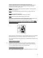
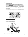
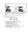
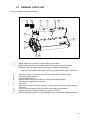
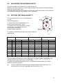
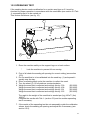
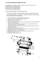
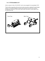
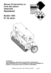
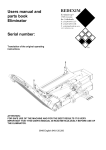
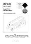
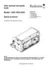
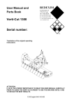
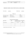
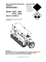
User manual and parts manual SPEEDSEED Model 1200 / 1600 2100 / 2400 Serial number: Translation of the original operating instructions ATTENTION: TO ENSURE SAFE USE OF THIS MACHINE AND TO BE ABLE TO ACHIEVE THE BEST RESULTS, IT IS OF MAJOR IMPORTANCE TO READ THIS USER MANUAL THOROUGHLY BEFORE USING THE SPEEDSEED. 1015 English 924.120.200 FOREWORD Congratulations with the purchase of your Speedseed. To ensure long and safe use of this Speedseed, it is of major importance to all users to read and understand this user manual. Operation of this machine is not safe without full knowledge of the content of the manual. The Speedseed is not an independently operating machine. The user is responsible for using the appropriate tractor. The user must also check the tractor/ Speedseed combination for safety aspects, such as noise level, adequate user instructions and any risks. The Speedseed is solely intended for use on lawns and other areas where grass could grow. On the next page you will first find the general safety instructions. Every user must know and apply them. After this, a registration card is included. This card should be returned for handling any future claims. This user manual offers many instructions numbered in sequence. This sequence should be observed. An asterisk * indicates a safety instruction. An @ indicates a tip and/or note. All information and technical specifications provided at the moment that this document is published are the most recent ones. Design specifications may be changed without prior notice. This document is a translation of the original operating instructions. Upon request, the original operating instructions are available in Dutch. GUARANTEE CONDITIONS THIS SPEEDSEED COMES WITH A GUARANTEE FOR DEFECTIVE MATERIALS. THIS GUARANTEE IS VALID FOR A PERIOD OF 12 MONTHS FROM THE PURCHASING DATE. SPEEDSEED GUARANTEES ARE SUBJECT TO THE “GENERAL CONDITIONS FOR SUPPLY OF PLANT AND MACHINERY FOR EXPORT, NUMBER 188”, PUBLISHED UNDER THE AUSPICES OF THE UNITED NATIONS ECONOMIC COMMISSION FOR EUROPE. REGISTRATION CARD For your own information, please complete the table below: Serial number of machine Dealer name Purchasing date Remarks 2 ! Fig. 1 (1) SAFETY INSTRUCTIONS ! The design of the Speedseed allows for safe use. However, this is only possible if the user fully observes the safety instructions given in this manual. Read and understand (Fig. 1) the manual before starting to use the Speedseed. Not using the machine as described in the manual may lead to injury and/or damage to the Speedseed. The Speedseed is solely intended for tilling lawns or areas where grass should grow. Any other use is considered to be incorrect use. The manufacturer does not accept any liability with regard to damage resulting from incorrect use; all resulting risks are the responsibility of the user. Correct use also includes following the manufacturer’s instructions for use, maintenance and repair. Before using the Speedseed, inspect the area to be treated. Remove any loose obstacles and avoid irregularities. (2) The Speedseed was constructed according to the latest technological knowledge and is safe to use. Improper use, maintenance or repair of the machine may result in injury to both the user and others. This should be avoided! Always use the Speedseed in combination with the appropriate tractor as described in the technical data. (3) All persons whom the owner assigns to operate, maintain or repair the Overseeder must read and completely understand the operating manual and in particular the Safety Instructions section. The user is responsible for a safe tractor/Speedseed combination. This unit must be tested in terms of noise, safety and ease-of-use. In addition, user’s instructions must be prepared. (4) Before using the Speedseed, the user is obliged to inspect it for visible damage and defects. Any changes of the Speedseed (including its functioning) that may affect its safety must be corrected immediately. For safety reasons it is in principle forbidden to make changes in or additions to the Speedseed (with the exception of those approved by the manufacturer). If any modifications have been made to the Speedseed, the present CE certificate becomes null and void and the person who made the modifications should himself make sure a new CE certificate is granted. 3 Inspect the Speedseed for loose bolts/nuts/parts before each use. If present, inspect the hydraulic hoses regularly and replace them if they are damaged or show signs of wear. The replacement hoses must meet the manufacturer’s technical specifications. Always relieve the pressure from the hydraulic installation, if present, before carrying out any work on it. NEVER use de Speedseed when protective covers and safety stickers are missing. NEVER crawl under the Speedseed. Tilt the Overseeder if you need to have access to the bottom. NEVER step off the tractor while the engine is still running. When carrying out maintenance activities, adjustments or repairs make sure the Speedseed is locked to prevent it from sinking/riding/sliding away. When carrying out any maintenance activities, adjustments or repairs, always switch off the tractor engine first, remove the tractor key from the ignition and disconnect the PTO (Fig. 2). Fig. 2 When carrying out any maintenance or repair activities, make sure to use original Speedseed parts only. This will ensure safety for the machine and its user. Only authorised technical personnel may carry out adjustments and repairs to the Overseeder. Keep an overview of repairs. (5) In addition to the instructions in this user manual, the generally applicable regulations with respect to safety and working conditions must be observed. For use on public roads the relevant traffic rules also apply. Transporting persons is not permitted! Do not use the Speedseed when it is dark, during heavy rain/storms or on slopes with a gradient of more than 20 degrees. 4 (6) Before starting to work, all persons operating the Speedseed must be familiar with all its functions and controls. Connect the Speedseed to the vehicle that will pull it exactly according to the instructions (Danger of injury!) Before driving off, make sure you have a clear view both nearby and far away. On both sides of the Speedseed, safety stickers (Fig. 3, 4, 5) have been applied to the sideboards and to the back cover (Fig. 6) showing these warnings. Make sure these safety stickers are always clearly visible and legible. Replace them if they are damaged. During operation, make sure there are NO persons in the danger area of the Speedseed to prevent them from getting injured by moving parts (Fig. 3). fig.3 fig.4 Keep a distance of at least 4 metres! (Fig. 4) Be aware of the maximum lifting capacity of the towing vehicle. Wear suitable clothing. Wear sturdy shoes with a steel tip, wear long trousers, do up long hair and wear no loose clothing. Fig.5 (7) Location of safety stickers (Fig. 5). 5 CONTENTS Section Description Page Foreword 2 Guarantee conditions 2 Registration card 2 Safety instructions 3 1.0 Technical data 7 2.0 First installation, removing the machine from the pallet 9 3.0 General parts list 10 4.0 Adjusting the working depth 11 5.0 Setting the seed quantity. 11 6.0 Transporting the speedseed 12 7.0 Driving speed 12 8.0 General remarks on the use of the speedseed 12 9.0 Operating the speedseed 12 10.0 Start/stop procedure 12 11.0 Disconnecting the speedseed 13 12.0 Troubleshooting 14 13.0 EU certificate 14 14.0 Maintenance 15 15.0 Adjusting the seeding slit opening 16 15.1 Adjusting the seed-tray scraper 16 15.2 Spreading test 17 16.1 Option Spikes on rear roller 18 16.2 Option wheel kit 19 Parts pages 6 1.0 TECHNICAL DATA Model 1200 1600 Working width 1.2 m (82.7”) 1.58 m (94.4”) Working depth 5 mm – 20 mm (0.19” - 0.78”) 5 mm - 20 mm (0.19” - 0.78”) Seeding speed Up to 12 km/h (7.5 mph) Up to 12 km/h (7.5 mph) Weight 350 g (772 lbs) 450kg (992 lbs) Seeding hole spacing Square 30 mm (1.18”) Square 30 mm (1.18”) Number holes/ sq meter with single spiked roller 990 990 Recommended tractor 20 HP with minimum lifting capacity of 450 kg (990 lbs) 30 HP with minimum lifting capacity of 550 kg (1212 lbs) Seed-tray capacity Maximum capacity 168 litres (5.9 cu. ft.) 14175 m2 (152523 ft2) 225 litres (7.9 cu. ft.) 18900 m2 (203438 ft2) Seeding density per 100 m2 (1076.4 ft2) Fine seed: 0.2 - 2.8 kg (0.44 - 6.17 lbs) (adjustable in 10 steps) Coarse seed: 0.2 - 4 kg (0.44 – 8.82 lbs.) (adjustable in 10 steps) Fine seed: 0.2 - 2.8 kg (0.44 - 6.17 lbs) (adjustable in 10 steps) Coarse seed: 0.2 - 4 kg (0.44 – 8.82 lbs.) (adjustable in 10 steps) Shipping dimensions Three-point connection LxWxH 1500 x 870 x 1070 mm 75x34x42” Three-point CAT 1-2 LxWxH 1900 x 870 x 1070 mm 75x34x42” Three-point CAT 1-2 Lubricant EP 2 EP 2 Tyre pressure 1 – 2 bar (14.5 - 29 psi) 1 – 2 bar (14.5 - 29 psi) Standard parts 5 gear sets for adjusting the seeding density. Manual container. Seed tray with sight-glass. Seeding wheel adjusting to the area. 5 gear sets for adjusting the seeding density. Manual container. Seed tray with sight-glass. Seeding wheel adjusting to the area. Option Set of spikes for back roller Set of spikes for back roller (theoretically at maximum speed 12 km/h (7.5 mph) and single passage) 7 Model 2100 2400 Working width 2.1 m (47.2”) 2.4 m (62.2”) Working depth 5 mm – 20 mm (0.19” - 0.78”) 5 mm - 20 mm (0.19” - 0.78”) Seeding speed Up to 12 km/h (7.5 mph) Up to 12 km/h (7.5 mph) Weight 550 g (772 lbs) 700kg (992 lbs) Seeding hole spacing Square 30 mm (1.18”) Square 30 mm (1.18”) Number holes/ sq meter with single spiked roller 990 990 Recommended tractor 40 HP with minimum lifting capacity of 1000 kg (2200 lbs) 40 HP with minimum lifting capacity of 1000 kg (2200 lbs) Seed-tray capacity Maximum capacity 225 litres (7.9 cu. ft.) 24900 m2 (268021 ft2) 336 litres (11.8 cu. ft.) 28350 m2 (305046 ft2) Seeding density per 100 m2 (1076.4 ft2) Fine seed: 0.2 - 2.8 kg (0.44 - 6.17 lbs) (adjustable in 10 steps) Coarse seed: 0.2 - 4 kg (0.44 – 8.82 lbs.) (adjustable in 10 steps) Fine seed: 0.2 - 2.8 kg (0.44 - 6.17 lbs) (adjustable in 10 steps) Coarse seed: 0.2 - 4 kg (0.44 – 8.82 lbs.) (adjustable in 10 steps) Shipping dimensions Three-point connection LxWxH 2415 x 870 x 1070 mm 134x34x42” Three-point CAT 1-2 LxWxH 2700 x 870 x 1070 mm 150x34x42” Three-point CAT 1-2 Lubricant EP 2 EP 2 Tyre pressure 1 – 2 bar (14.5 - 29 psi) - Standard parts 5 gear sets for adjusting the seeding density. Manual container. Seed tray with sight-glass. Seeding wheel adjusting to the area. 5 gear sets for adjusting the seeding density. Manual container. Seed tray with sight-glass. Seeding wheel adjusting to the area. Option Set of spikes for back roller Set of spikes for back roller (theoretically at maximum speed 12 km/h (7.5 mph) and single passage) 8 Fig. 6 2.0 FIRST INSTALLATION, REMOVING THE MACHINE FROM THE PALLET The machine is standing vertically on the pallet. To remove the pallet and lay the machine horizontally on the ground, proceed as follows (see Fig. 6): 1. Fasten a cable to the lifting point (2). * Make sure that the cable/crane/lift can lift at least SS 1200 500 kg (1100 lbs) SS 1600 600 kg (1322 lbs) SS 2100 700 kg (1540 lbs) SS 2400 850 kg (1870 lbs) 2. Raise the machine, including the pallet, 50 mm (2”) from the ground. 3. Remove the pallet by sliding it over the lower 3-point pins * Do not crawl under the machine!! 4. Slowly lower the machine until it is standing on the ground. 5. Attach the machine to a tractor. * Use the correct tractor. See the specifications. 6. Set the tractor’s stabiliser to 100 mm lateral movement. 7. Drive to the area that is to be tilled. 8. While driving carefully lower the machine into the ground. 9. Switch off the tractor and lock the tractor/Speedseed combination to prevent it from driving/sliding away. 10. Turn the top rod to adjust the machine angle to 90 degrees. 9 3.0 GENERAL PARTS LIST Figure 7 shows some important parts: 1 4 2 3 8 11 9 5 2 6 7 10 Fig. 7 1. 2. Safety sticker RA, read user manual before use/toolbox. Safety sticker 911.280.402, keep a distance of at least 4 metres from the machine. Stop the engine before carrying out repairs or adjustments. * 3. 4. 5. 6. 7. 8. 9. 10. 11. Make sure all stickers are clearly visible on the machine and are understood. The serial number is at the front on the three-point plate of the machine. Three-point fastening pins. Free adjustable brush. Access hatch to the transmission for setting the seeding density. Seeding wheel adjusting to the area. Seed tray. Here also the various change gears for configuring the required seeding density are found. Cover providing access to the secondary drive chain and tensioner. Adjustment screw of chain tensioner primary drive chain. Sticker indicating the various gear settings and the associated seeding densities. 10 4.0 ADJUSTING THE WORKING DEPTH The working depth can be adjusted by turning the top rod. When the top rod is turned and, consequently, shortened the machine will incline forwards, setting the seeding depth lower. This works when the ground to be tilled is soft enough. When the ground is not soft enough try to make this softer by using irrigation or the verti-drain®. 5.0 SETTING THE SEED-QUANTITY The seed quantity can be set on the Speedseed by using various change gears. These provide various combinations for a broad range of settings (see Tab 1). The gears have been marked with a number given in Tab. 1; by changing the gears as indicated, the required quantity setting is obtained. The different combinations of gears have been installed in the seed tray. Fig. 8 Gear option Bottom Top 25 95 40 80 45 75 52 68 Bentgrass Kentucky Bluegrass Ryegrass Kg/100m2 Lbs/1000ft2 Kg/100m2 Lbs/1000ft2 Kg/100m2 Lbs/1000ft2 0.20 0.40 0.20 0.40 0.30 0.60 0.40 0.80 0.35 0.70 0.55 1.10 0.45 0.80 0.40 0.80 0.65 1.30 0.60 1.20 0.50 1.00 0.85 1.75 58 62 0.70 1.40 0.60 1.20 1.00 2.00 62 58 0.80 1.60 0.75 1.50 1.20 2.45 68 52 1.00 2.00 0.90 1.80 1.40 2.80 75 45 1.30 2.60 1.10 2.20 1.90 3.85 80 40 1.50 3.00 1.40 2.80 2.20 4.45 95 25 2.80 5.70 2.60 5.30 4.15 8.40 Tab. 1 These quantities are determined with a slit distance of 0.3 mm between the seeding roller and the pressure plate (see section 15.0 for setting). In practice the quantities described in Tab. 1 may deviate to some extent due to other measuring/working conditions. @ In order to determine exactly the right seeding quantity for the seed used, it is recommended to carry out a spreading test (see section 15.2). 11 6.0 TRANSPORTING THE SPEEDSEED The user is responsible for the transport of the Speedseed behind the tractor when travelling on public roads. Check the national traffic rules. In view of the weight of the Speedseed, a maximum speed of 20 km/h (12.4 mph) should be observed while driving in open fields with the machine raised. Higher speeds may endanger the driver and/or other people and even damage the machine. * When the machine is in the raised position, at least 20% of the weight of the tractor should be supported by the front axle. 7.0 DRIVING SPEED The driving speed is limited to 12 km/h (7.5 mph). Higher speeds are not recommended in view of excessive wear and damage that may occur to the machine due to, for example, rocks in the ground. 8.0 GENERAL REMARKS ON THE USE OF THE SPEEDSEED. Some general remarks/tips on the use of the Speedseed. @ A field can be tilled 2 or 3 times in different directions in order to obtain a higher seeding density. @ Do not make sharp turns. @ When hitting a hard object in the soil, the spike-elements may be burred/damaged. Try to file burrs away or replace the spike-element. @ NEVER drive backwards while the running wheel is on the ground. 9.0 OPERATING THE SPEEDSEED Before using the Speedseed in the field, check the following: 1. Are there any loose objects in the field? Remove these first. 2. Are there any slopes? The maximum slope this machine can work on is 20 degrees. Always work downhill. 3. Does the ground contain hard objects? If so, use the Speedseed at a low speed and adjust the working depth. 4. Is there any danger of flying objects, such as golf balls, which may distract the attention of the driver? If so, do NOT use the Speedseed. 5. Is there any danger of sinking or sliding away? If so, postpone the work. 6. If the soil is frozen or very wet, the work should be postponed until the conditions are more favourable. 10.0 STARTING/STOPPING PROCEDURE Before starting the seeding, check the machine for the following points: * While checking the machine/tractor combination must be fully locked to prevent it from driving/sliding/sinking away. The tractor engine must be switched off. Check the seeding elements for damage and repair if necessary. Check the seed spreading by rotating the running wheel 1 time (counterclockwise). 12 Check if the drive is running smoothly. Check the tyre pressure. START SEEDING. The starting procedure is VERY important. If this procedure is not followed exactly as described below, serious damage may occur to the machine. The procedure is as follows: 1. Put the seed in the seed tray. 2. Set the required seed quantity using the change wheels (see section 5.0). 3. Drive to the place where you want to start. 4. Start with a driving speed of about 3 km/h (1.9 mph). 5. While driving lower the machine carefully and in a controlled way until the spike elements are cutting the ground. 6. If necessary, stop the spike elementsin the ground to adjust the working depth (see section 4.0). * While adjusting, the machine/tractor combination must be fully locked to prevent it from driving/sliding/sinking away. The tractor engine must be switched off. 7. Increase the speed until the correct driving speed has been reached. STOP SEEDING 1. Decrease the driving speed to about 3 km/h (1.9 mph). 2. While driving, raise the machine out of the ground. 3. Go to the following place and start again as described. @ It is absolutely imperative that the above procedures are followed @ While driving, lower the machine CAREFULLY AND IN A CONTROLLED WAY during the tilling. @ NEVER drive backwards when the running wheel is on the ground. 11.0 DISCONNECTING THE SPEEDSEED The machine can be disconnected from the tractor as follows: 1. 2. 3. 4. Slowly lower the machine until it stands on the ground. Lock the roller to prevent it from rolling away. Loosen the top rod and remove it. Remove the lower arms from the tractor of the speedseed. * Place the machine on a stable and level surface and make sure that the machine is stable and cannot slide. * Switch off the tractor engine when people are walking around the machine and lock the tractor/machine combination to prevent it from moving! @ When you store the machine lower the machine carreful to prefent the spikes against damage. 13 12.0 TROUBLESHOOTING Problem Seed is spoilt from the seed tray. Possible cause Seeding slit too large. Solution Readjust the seeding slit. Set the scraper closer to the Distance between the scraper seeding roller. and the seeding roller is too large. Tape up/glue. The machine does not reach the required depth. The adjustment plate of the seeding slit on the side is leaking. Tractor tensioning is too low. Put drawing arms into a higher hole. Ground is too hard. Aerate/irrigate. Top rod is incorrectly adjusted. Drive wheel is slipping Correctly adjust the top rod. Too much dead leaves and roots in the top layer of the field. Remove the dead leaves and roots. Not enough weight. Add weight. Ground is too wet. Postpone the tilling. Tyre pressure is too low. Inflate. Dose-measuring roller is dirty. Clean the dose-measuring roller. Chain drive is rigid. Lubricate. 13.0 EU CERTIFICATE We, Redexim BV, Utrechtseweg 127, 3702 AC Zeist, The Netherlands, declare entirely on our own responsibility that the product SPEEDSEED MODEL 1200 / 1600 / 2100 / 2400, WITH MACHINE NUMBER AS INDICATED ON THE MACHINE AND IN THIS MANUAL, to which this declaration relates is according to the stipulation of the 2006/42/EC directive for machines. Zeist, 01/10/09 A.C. Bos Manager Operations & Logistics Redexim Holland 14 14.0 MAINTENANCE Time schedule Check point/lubricating point Method Before each use Check for loose bolts/nuts. Tighten the loose bolts/nuts with the correct torque. Presence and legibility of safety Replace if damaged or stickers (Fig. 5). missing. After first 20 operating hours (new or repaired) After every 100 operating hours. Grease the roller bearings. Use EP 2 lubricating grease. Check for loose bolts/nuts. Tighten the loose bolts/nuts with the correct torque. Grease the drive chains. Use a chain spray. Grease the roller bearings Check for loose bolts/nuts. Use EP 2 lubricating grease. Tighten the loose bolts/nuts with the correct torque. Grease the drive chains. Use a chain spray. Check the tension of the drive chains. Tension the tensioners of the drive chains. Check the seeding roller for dirt/damage. Clean the seeding roller or replace it if necessary. Check the seeding slit opening. Adjust the seeding slit if necessary. Check the seed quantity. Carry out a spreading test. Check the spike elements for damage. Repair or replace if necessary. 15 15.0 ADJUSTING THE SEEDING SLIT OPENING Fig. 9 If the seed production does not correspond with the table, the seeding slit may need adjustment. This is done as follows: (see fig. 9) 1. Loosen all lock nuts 3. 2. Adjust bolt 4 such that a feeler gauge of 0.3 mm (0.012”) can be slit just between the roller 1 and the adjustment plate. 3. Check all bolts 4 and calibrate the slit opening between roller 1 and adjustment plate 2 along the entire width of the machine to 0.3 mm (0.012”). 4. Turn roller 1 half a turn and measure the slit opening. If necessary adjust it to 0.3 mm (0.012”) by turning bolt 4 in or out. 5. Tighten the lock nuts 3. @ The split opening should be equal along the entire width of the roller. @ The slit opening must have the same size as the smallest seed part. This opening is default set to 0.3 mm. 15.1 ADJUSTING THE SEED-TRAY SCRAPER When the seeding tray is spoiling seed, the scraper setting may be incorrect. To adjust this, proceed as follows (see fig. 9): 1. Loosen bolts and nuts 6. 2. Move scraper 5 up or down until the correct setting has been obtained. 3. Re-tighten the bolts and nuts 6. @ The distance between roller 1 and scraper 5 is default set to 0.8 mm and should be equally set along the entire width of the roller. 16 15.2 SPREADING TEST If the seeding device needs recalibration for a certain seed type or if it must be checked for proper operation in accordance with the seed table (see section 5.0 Tab 1) a spreading test is to be carried out. This is done as follows: (see fig. 10). 1 2 Fig. 10 1. Place the machine safely on the support legs on a level surface. * Lock the machine to prevent it from moving. 2. First of all check the seeding slit opening for correct setting (see section 15.0). 3. Put the seed that is to be calibrated into the seed tray (1) and spread it equally over the tray. 4. Place a collecting back under the machine to collect the seed. 5. Turn the wheel (2) 13 full rotations counterclockwise. 6. Weigh the seed that is collected and multiply this by 5.09 (SS1200). Weigh the seed that is collected and multiply this by 4.08 (SS1600). Weigh the seed that is collected and multiply this by 2.91 (SS1600). Weigh the seed that is collected and multiply this by 2.55 (SS1600). The result is the weight of the seed that is seeded per (kg) 100m2 / (lbs) 1000 ft2. Compare the results with Tab. 1 (section 5.0) and do another spreading test if necessary. 7. If the results of the spreading test do not reasonably match the calibration values, check the seeding slit opening and adjust this if necessary (see section 15.0). 17 16.1 OPTION SPIKES ON REAR ROLLER It is possible to mount spikes on the second roller. Article number for this is: 224.120.000 for the speedseed 1200 224.160.002 for the speedseed 1600. 224.210.000 for the speedseed 2100. 224.240.000 for the speedseed 2400. For mounting the spikes, follow the next rulles. *Take care that when you assemble the spikes the cable and crane can lift at least 600 kg. Crawl never under the machine, and take care of the sharp points on the spikes. 1. 2. 3. 4. 5. Be sure the machine is blocked against moving away. Lif the machine at the back side from the ground Demount the rear cover plate # 2 Demount the rear roller # 1 Demount the scraper # 3 store this one till you start working without the spikes on the second roller again. 6. Demount the brush # 4 and the blockbolts # 5. To remove the brush only demount bolt # 6. Do not remove bolt # 7. 7. Assemble inside the rear roller # 1 on one side the four bolt M8 x 16 # 8 with the self lock nuts # 9 8. Assemble the spikes on the roller # 10 9. Assemble the other side also the four bolts M8 x 16 # 9 with the self lock nuts. 10. Assemble the roller # 1 in the holes # 11 11. Assemble the brush # 4 with the blockbolts # 5 in the holles # 12 12. Assemble the rear cover # 2 13. Lower the machine to the ground. 2 12 7 5 5 11 6 4 3 10 8 1 8 9 18 16.2 OPTION WHEEL KIT Article number for this is 224.160.000, and is only arranged for the speedseed 1600. This kit will be separately delivered and can be mounted to a standard 3-point linkage machine. Generally speaking, a machine with wheel kit will reduce the minimum horsepower required by 10 HP It also can be taken off quickly, so the machine can be used either way. Front View Back View 19