1
APPLICATION NOTE
Renesas USB MCU
R01AN2664EJ0111
Rev.1.11
Sep 30, 2015
USB Peripheral Human Interface Devices Class Driver
Using Firmware Integration Technology Modules
Introduction
This document describes the following sample firmware: USB Peripheral Human Interface Devices Class Driver for
using Firmware Integration Technology. The sample firmware is referred to below as the PHID. During actual software
development, make sure to refer to the USB Peripheral Human Interface Devices Class Driver f using Firmware
Integration Technology application note (document No. R01AN2663EJ) in combination with the USB Basic Host and
Peripheral Driver using Firmware Integration Technology application note (document No. R01AN2025EJ) and the
user’s manual (hardware) of the microcontroller used.
Target Device
RX63N/RX631 Group
RX64M Group
RX71M Group
The operation of this program has been confirmed using the Renesas Starter Kit (RSK).
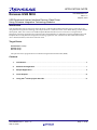
Contents
1.
Introduction ..................................................................................................................................... 2
2.
Software Configuration................................................................................................................... 7
3.
Sample Application ......................................................................................................................... 8
4.
Class Request ................................................................................................................................ 18
5.
Using the e2 studio project with CS+ ........................................................................................... 19
R01AN2664EJ0111
Sep 30, 2015
Rev.1.11
Page 1 of 20
Renesas USB MCU
1.
USB Peripheral Human Interface Devices Class Driver Using Firmware Integration Technology Modules
Introduction
1.1
Functions
The PHID conforms to the USB human interface device (HID) class specification and implements communication with
HID devices.
The PHID provides the following functionalities:
1.
2.
1.2
Operation as a Full-Speed (12 Mbps) device.
It is recognized as an HID device when connected to a USB host, and transfers data as a virtual mouse or virtual
keyboard.
FIT Module Configuration
The PHID comprises the following FIT modules and a sample application:
Table 1-1
FIT Module Configuration
FIT Module
Board Support Package Module
Using Firmware Integration Technology
Renesas USB MCU USB Basic Host and Peripheral firmware
Firmware Integration Technology
Renesas USB MCU USB Peripheral Human Interface Devices Class
Driver(HID) Firmware Integration Technology
Folder Name
Version
r_bsp
2.81
r_usb_basic
1.11
r_usb_phid
1.11
Refer to the related documentation for details of each FIT module. Note that the latest versions of the FIT modules used
by the sample firmware are available for download from the following website:
Renesas Electronics website: http://www.renesas.com/
R01AN2664EJ0111
Sep 30, 2015
Rev.1.11
Page 2 of 20
Renesas USB MCU
1.3
USB Peripheral Human Interface Devices Class Driver Using Firmware Integration Technology Modules
Operating Confirmation Environment
The environment required for the PHID to operate is described below:
1)
Evaluation Board
Renesas Starter Kit+ for RX63N (RSK+RX63N): Product No: R0K50563NC000
RX63N Group Renesas Microcontroller Development Starter Kit from Renesas Electronics
Renesas Starter Kit+ for RX64M (RSK+RX64M): Product No: R0K50564MC010BR
RX64M Group Renesas Microcontroller Development Starter Kit from Renesas Electronics
Renesas Starter Kit+ for RX71M (RSK+RX71M): Product No: R0K5RX71MC010BR
RX71M Group Renesas Microcontroller Development Starter Kit from Renesas Electronics
2)
Development Environment
a) e studio integrated development environment, from Renesas Electronics
b) RX Family C/C++ compiler package, version 2.03.00, from Renesas Electronics
c) E1 or E20 emulator from Renesas Electronics
2
3)
Other
a)
b)
c)
d)
e)
HID Host (PC: Microsoft Windows® 7, Windows® 8, Windows® 8.1, or Windows® 10)
Host PC for emulator (Microsoft Windows® 7, Windows® 8, or Windows® 8.1)
USB cable
User cable (packaged with E1 or E20 emulator)
Emulator cable (packaged with E1 or E20 emulator)
R01AN2664EJ0111
Sep 30, 2015
Rev.1.11
Page 3 of 20
Renesas USB MCU
1.4
1.4.1
USB Peripheral Human Interface Devices Class Driver Using Firmware Integration Technology Modules
Setup
Hardware
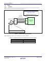
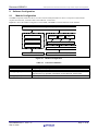
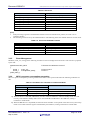
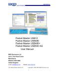
Figure 1-1 shows an example operating environment for the PHID. Refer to the associated instruction manuals for
details on setting up the evaluation board and using the emulator, etc.
Peripheral Human Interface Device
Class Driver (PHID)
+
USB Basic Peripheral Driver
USB Cable
Enumeration
(Control Transfer)
USB Host (PC)
USB
PORT
Interrupt IN data transfer
Interrupt OUT data transfer
USB
PORT
Evaluation
Board
OS:Windows 7/ Windows 8/ Windows 8.1/ Windows 10 etc
Figure 1-1
Example Operating Environment
Table 1-2 shows the evaluation board on which operation has been confirmed.
Table 1-2
R01AN2664EJ0111
Sep 30, 2015
Evaluation Board on which PHID operation has been verified
Rev.1.11
MCU
Evaluation Board
RX63N
RX64M
RSK+RX63N
RSK+RX64M
RX71M
RSK+RX71M
Page 4 of 20
Renesas USB MCU
1.4.2
USB Peripheral Human Interface Devices Class Driver Using Firmware Integration Technology Modules
Software
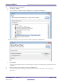
Setup e2 studio
1)
a)
Start e2 studio
b)
If you start up e2 studio at first, the following dialog is displayed. Specify the folder to store the project in this
dialog.
c)
Click Workbench icon
R01AN2664EJ0111
Sep 30, 2015
Rev.1.11
Page 5 of 20
Renesas USB MCU
2)
USB Peripheral Human Interface Devices Class Driver Using Firmware Integration Technology Modules
Import the project to the workspace
a)
Select [File] > [Import]
b)
Select “General => Rename & Import Existing C/C++ Project into Workspace”
Select the root directory of the project, that is, the folder containing the “.cproject” file.
c)
Click “Finish”.
You have now imported the project into the workspace. Note that you can import other projects into the same
workspace.
3)
Generate the binary target program by clicking the “Build” button.
4)
Connect the target board to the debug tool and download the executable. The target is run by clicking the
“Run” button.
R01AN2664EJ0111
Sep 30, 2015
Rev.1.11
Page 6 of 20
Renesas USB MCU
2.
2.1
USB Peripheral Human Interface Devices Class Driver Using Firmware Integration Technology Modules
Software Configuration
Module Configuration
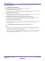
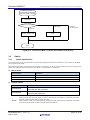
The PHID comprises a HID class driver as well as mouse and keyboard device drivers. In response to data transfer
requests from the APL, it transfers data to the USB host, via the PCD.
Figure 2-1 shows the module configuration of the PHID, and Table 2-1 lists the functions of the modules.
User application (APL)
RSK driver
PHID
LCD output driver
Keyboard
Mouse
Echo
LED output driver
USB Peripheral HID class driver (PHID)
Switch input driver
USB Peripheral Control Driver (PCD)
LCD/LED/KEY (H/W)
USB Peripheral controller (H/W)
Figure 2-1
Module Configuration
Table 2-1
Function of Moudles
Module Name
Function
APL
Sample application program
RSK driver
PHID (r_usb_phidi)
Sample application for using the peripheral functions on the RSK board.
PCD (r_usb_basic)
USB Peripheral Hardware Control Driver
R01AN2664EJ0111
Sep 30, 2015
Interprets requests from the HID host.
Reports APL key operation information to the HID host, via the PCD.
Rev.1.11
Page 7 of 20
Renesas USB MCU
3.
USB Peripheral Human Interface Devices Class Driver Using Firmware Integration Technology Modules
Sample Application
3.1
Application Specifications
The main functionalities of the PHID sample application (APL) are described below.
(1). Keyboard Mode: Keyboard Functionality
When the RSK connects to the USB host, the USB host recognizes the RSK as a keyboard. The RSK operates
as a keyboard, transmitting keyboard data to the USB host using interrupt IN transfer.
(2). Mouse Mode: Mouse Functionality
When the RSK connects to the USB host, the USB host recognizes the RSK as a mouse. The RSK operates as a
mouse, transmitting mouse data to the USB host using interrupt IN transfer.
(3). Echo Mode: USB Loopback Functionality (Interrupt IN/OUT Data Transfer)
The RSK connects to the USB host and performs interrupt IN/OUT data transfer. This functionality performs
processing to transmit the data received from the USB host back to the USB host unaltered.
(4). Low-Power-Consumption Functionality
This functionality transitions the microcontroller to a low-power mode according to the USB state. To enable
this functionality, set the macro definition USB_CPU_LPW_PP to USB_LPWR_USE_PP in the file
r_usb_basic_config.h.
a) In the USB suspend state, the microcontroller transitions to sleep mode.
b) In the USB detached state, the microcontroller transitions to software standby mode.
[Note]
1.
Make the selection of keyboard mode, mouse mode, or other mode in r_usb_phid_config.h. For details, see the
application note “USB Peripheral Human Interface Device Class Driver for USB Firmware Firmware
Integration Technology” (document No. R01AN2663EJ).
2.
Echo mode enables communication with USB hosts supporting USB loopback functionality. Keyboard mode
and mouse mode enable USB communication with PCs (USB hosts) supporting OSes such as Windows 7,
Windows 8, Windows 8.1 and Windows 10.
R01AN2664EJ0111
Sep 30, 2015
Rev.1.11
Page 8 of 20
Renesas USB MCU
3.2
USB Peripheral Human Interface Devices Class Driver Using Firmware Integration Technology Modules
Overview of Application Processing
The APL consists of two parts: processing of initial settings and the main loop. These are described in outline below.
3.2.1
Initial setting
The initial settings include microcontroller pin settings, USB driver settings, and USB controller initial settings.
3.2.2
Main loop (Mouse mode)
In Mouse mode the main loop performs the following processing:
a)
When enumeration with the USB host finishes, the USB driver calls the function hid_open, which is specified by
member devconfig of structure USB_PCDREG_t. The function hid_open sets EVENT_CONFIGURED as the
event value.
b)
The processing of EVENT_USB_WRITE_START calls the function R_usb_phid_send_data to request
transmission of mouse data by the USB driver. When transmission of the mouse data finishes, the callback
function hid_write_trans_cb, specified by the 4th argument of the function R_usb_phid_send_data, is called. This
callback function sets EVENT_USB_WRITE_COMPLETE as the event value.
c)
The processing of EVENT_USB_WRITE_COMPLETE sets the transmission status variable to “not transmitting.”
d)
The processing of EVENT_SUSPEND calls the function hid_low_power_control to transition the HID device
(RSK) to the low-power mode (sleep mode). Note that if the HID device (RSK) is in the suspend state, it is woken
from the suspend state when a resume signal transmitted by the USB host is detected.
e)
The processing of EVENT_NONE captures key input information. When SW1 is pressed:
i. If the HID device is in the suspend state, a RemoteWakeUp signal is sent to the USB host by means of the
R_usb_phid_ChangeDeviceState function.
ii. If the HID device is in the configured state, processing to set the key data (mouse data) is performed and the
event value is set to EVENT_USB_WRITE_START in order to transmit the specified data to the USB host.
The transmission status variable is set to “transmitting.”
f)
If the USB host transmits a suspend signal to the HID device (RSK) while steps b) to e) above are being processed
repeatedly, the USB driver calls the function hid_suspend specified by member devsuspend in structure
USB_PCDREG_t. The function hid_suspend sets EVENT_SUSPEND as the event value.
g)
The processing of EVENT_SUSPEND calls the function hid_low_power_control to transition the HID device
(RSK) to the low-power mode (sleep mode). Note that if the HID device (RSK) is in the suspend state, it is woken
from the suspend state when a resume signal transmitted by the USB host is detected.
h)
If the HID device (RSK) is detached from the USB host while steps b) to e) above are being processed repeatedly,
the USB driver calls the function hid_close specified by member devdetach in structure USB_PCDREG_t. The
function hid_close sets EVENT_DETACH as the event value.
i)
The processing of EVENT_DETACH calls the function R_usb_phid_TransferEnd to transition the HID device
(RSK) to the low-power mode (software standby mode) after the data transfer request ends. If the HID device
(RSK) is attached to the USB host again, enumeration starts with the USB host and the processing resumes from
step a) above.
R01AN2664EJ0111
Sep 30, 2015
Rev.1.11
Page 9 of 20
Renesas USB MCU
USB Peripheral Human Interface Devices Class Driver Using Firmware Integration Technology Modules
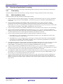
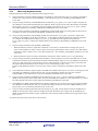
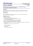
An outline of the processing of the APL is shown below.
PHID APL
(usb_main)
Initialization
Getting the event
(hid_event_get)
EVENT_USB_WRITE_START ?
Y
Data sending request
(R_usb_phid_send_data)
Y
Setting “Not sending status”
to Sending status variable
Y
Low power consumption processing
(hid_low_power_control)
N
EVENT_USB_WRITE_COMPLETE ?
N
EVENT_SUSPEND ?
N
EVENT_DETACH ?
Y
N
Data transfer stop processing
(R_usb_pstd_TransferEnd)
Low power consumption processing
(hid_low_power_control)
Switch check processing
EVENT_NONE ?
Switch check processing
Getting the key data
Getting USB device status
(R_usb_phid_DeviceInformation)
USB device status
== Suspend ?
Y
REMOTE_WAKEUP
signal sending
N
Sending HID data in progress ?
(Sending status variable)
N
Sending the data setting
Setting “Sending status” to Sending status variable
Setting “EVENT_USB_WRITE_START”
Y
Figure 3-1
R01AN2664EJ0111
Sep 30, 2015
Rev.1.11
Main Loop Processing (Mouse mode)
Page 10 of 20
Renesas USB MCU
3.2.3
USB Peripheral Human Interface Devices Class Driver Using Firmware Integration Technology Modules
Main loop (Keyboard mode)
In keyboard mode the main loop performs the following processing:
a)
When enumeration with the USB host finishes, the USB driver calls the function hid_open, which is specified by
member devconfig of structure USB_PCDREG_t. The function hid_open sets EVENT_CONFIGURED as the
event value.
b)
The processing of EVENT_CONFIGURED calls the function R_usb_phid_receive_data to request reception by
the USB driver of OUT data transmitted by the USB host. When reception of the OUT data finishes, the callback
function hid_read_trans_cb, specified by the 4th argument of the function R_usb_phid_receive_data, is called.
This callback function sets EVENT_USB_READ_COMPLETE as the event value.
c)
The processing of EVENT_USB_READ_COMPLETE performs LED display processing based on the received
OUT data, etc. It also sets EVENT_USB_READ_START as the event value.
d)
The processing of EVENT_USB_WRITE_START calls the function R_usb_phid_send_data to request data
transfer by the USB driver of the key input data, etc., to the USB host. When transmission of the key input data,
etc., finishes, the callback function hid_write_trans_cb, specified by the 4th argument of the function
R_usb_phid_send_data, is called. This callback function sets EVENT_USB_WRITE_COMPLETE as the event
value.
e)
The processing of EVENT_USB_WRITE_COMPLETE:
i. When transmission of the key input data is finished, it is necessary to transmit data consisting of 8 bytes of
zeroes to the USB host to notify it of key release. Processing is performed to set the necessary zero data and the
transmission status variable is set to “zero data transmission.” Also, EVENT_USB_WRITE_START is set as the
event value.
ii. When transmission of the zero data is finished, the transmission status variable is set to “not transmitting.”
f)
The processing of EVENT_NONE determines whether or not key input has occurred. If the HID device is in the
suspend state and SW1 is pressed and then released, a RemoteWakeUp signal is sent to the USB host by means of
the R_usb_phid_ChangeDeviceState function. If a key other than SW1 is pressed, processing to set the key data
takes place and the transmission status variable is set to “transmitting key data.” Also,
EVENT_USB_WRITE_START is set as the event value in order to transmit the specified key data to the USB
host.
g)
If the USB host transmits a suspend signal to the HID device (RSK) while steps b) to f) above are being processed
repeatedly, the USB driver calls the function hid_suspend specified by member devsuspend in structure
USB_PCDREG_t. The function hid_suspend sets EVENT_SUSPEND as the event value.
h)
The processing of EVENT_SUSPEND calls the function hid_low_power_control to transition the HID device
(RSK) to the low-power mode (sleep mode). Note that if the HID device (RSK) is in the suspend state, it is woken
from the suspend state when a resume signal transmitted by the USB host is detected.
i)
If the HID device (RSK) is detached from the USB host while steps b) to f) above are being processed repeatedly,
the USB driver calls the function hid_close specified by member devdetach in structure USB_PCDREG_t. The
function hid_close sets EVENT_DETACH as the event value.
j)
The processing of EVENT_DETACH calls the function R_usb_phid_TransferEnd to transition the HID device
(RSK) to the low-power mode (software standby mode) after the data receive request ends. If the HID device
(RSK) is attached to the USB host again, enumeration starts with the USB host and the processing resumes from
step a) above.
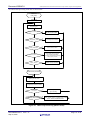
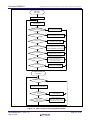
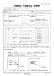
An outline of the processing of the APL is shown below.
R01AN2664EJ0111
Sep 30, 2015
Rev.1.11
Page 11 of 20
Renesas USB MCU
USB Peripheral Human Interface Devices Class Driver Using Firmware Integration Technology Modules
PHID APL
(usb_main)
Initialization
Getting the event
(hid_event_get)
EVENT_CONFIGURED ?
EVENT_USB_READ_START ?
Data receiving request
(R_usb_phid_receive_data)
Y
N
EVENT_USB_READ_COMPLETE ?
Y
Data receiving processing
“EVENT_USB_READ_START” Setting
Y
Data sending request
(R_usb_phid_send_data)
Y
Sending Data setting
Communication status variable setting
“EVENT_USB_WRITE_START” Setting
Y
Low power consumption processing
N
EVENT_USB_WRITE_START ?
N
EVENT_USB_WRITE_COMPLETE ?
N
EVENT_SUSPEND ?
(hid_low_power_control)
N
EVENT_DETACH ?
Y
N
EVENT_NONE ?
Data transfer stop processing
(R_usb_pstd_TransferEnd)
Low power consumption processing
(hid_low_power_control)
Y
Switch check processing
N
Switch checking
processing
Switch ON ?
N
Y
Getting USB device status
(R_usb_phid_DeviceInformation)
USB device status
== Suspend ?
Y
REMOTE_WAKEUP
Signal sending
N
HID Data sending
in progress ?
(Sending status variable)
N
Sending data setting
Seding status variable setting
“EVENT_USB_WRITE_START” Setting
Y
Figure 3-2
R01AN2664EJ0111
Sep 30, 2015
Rev.1.11
Main Loop Processing (Keyboard mode)
Page 12 of 20
Renesas USB MCU
3.2.4
USB Peripheral Human Interface Devices Class Driver Using Firmware Integration Technology Modules
Main loop (Echo mode)
In echo mode the main loop performs the following processing:
a)
When enumeration with the USB host finishes, the USB driver calls the function hid_open, which is specified by
member devconfig of structure USB_PCDREG_t. The function hid_open sets EVENT_CONFIGURED as the
event value.
b)
The processing of EVENT_CONFIGURED calls the function R_usb_phid_receive_data to request reception of
data from the USB host. When reception of the data finishes, the callback function hid_read_trans_cb, specified
by the 4th argument of the function R_usb_phid_receive_data, is called. This callback function sets
EVENT_USB_READ_COMPLETE as the event value.
c)
The processing of EVENT_USB_READ_COMPLETE calls the function R_usb_phid_send_data to transmit to the
USB host the data received in b) above. When reception of the data finishes, the callback function
hid_write_trans_cb, specified by the 4th argument of the function R_usb_phid_send_data, is called. This callback
function sets EVENT_USB_WRITE_COMPLETE as the event value.
d)
The processing of EVENT_USB_WRITE_COMPLETE sets EVENT_USB_READ_START as the event value.
e)
If the USB host transmits a suspend signal to the HID device (RSK) while steps b) to d) above are being processed
repeatedly, the USB driver calls the function hid_suspend specified by member devsuspend in structure
USB_PCDREG_t. The function hid_suspend sets EVENT_SUSPEND as the event value.
f)
The processing of EVENT_SUSPEND calls the function hid_low_power_control to transition the HID device
(RSK) to the low-power mode (sleep mode). Note that if the HID device (RSK) is in the suspend state, it is woken
from the suspend state when a resume signal transmitted by the USB host is detected.
g)
If the HID device (RSK) is detached from the USB host while steps b) to d) above are being processed repeatedly,
the USB driver calls the function hid_close specified by member devdetach in structure USB_PCDREG_t. The
function hid_close sets EVENT_DETACH as the event value.
h)
The processing of EVENT_DETACH calls the function R_usb_phid_TransferEnd to transition the HID device
(RSK) to the low-power mode (software standby mode) after the data transfer/receive request ends. If the HID
device (RSK) is attached to the USB host again, enumeration starts with the USB host and the processing resumes
from step a) above.
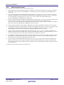
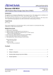
An outline of the processing of the APL is shown below.
R01AN2664EJ0111
Sep 30, 2015
Rev.1.11
Page 13 of 20
Renesas USB MCU
USB Peripheral Human Interface Devices Class Driver Using Firmware Integration Technology Modules
PHID APL
(usb_main)
Initialization
Getting Event
(hid_event_get)
EVENT_CONFIGURED ?
EVENT_USB_READ_START ?
Y
Data Receiving Request
(R_usb_phid_receive_data)
Y
Setting “EVENT_USB_WRITE_START”
Y
Data Sending Request
(R_usb_phid_send_data)
Y
Setting EVENT_USB_READ_START
N
EVENT_USB_READ_COMPLETE ?
(hid_event_set)
N
EVENT_USB_WRITE_START ?
N
EVENT_USB_WRITE_COMPLETE ?
(hid_event_set)
N
EVENT_SUSPEND ?
Y
Low power consumption processng
(hid_low_power_control)
N
EVENT_DETACH ?
Y
Data transfer stop processing
(R_usb_pstd_TransferEnd)
Low power consumption processing
(hid_low_power_control)
N
Figure 3-3
R01AN2664EJ0111
Sep 30, 2015
Rev.1.11
Main Loop Processing (Echo mode)
Page 14 of 20
Renesas USB MCU
USB Peripheral Human Interface Devices Class Driver Using Firmware Integration Technology Modules
Table 3-1 Event List
Event
Description
EVENT_CONFIGURD
EVENT_USB_READ_START
USB device connecting competion
Data reception request
EVENT_USB_READ_COMPLETE
EVENT_USB_WRITE_START
Data reception completion
Data transmission request
EVENT_USB_WRITE_COMPLETE
EVENT_SUSPEND
EVENT_DETACH
EVENT_NONE
Data transmission completion
Suspend
USB detach
No event
[Note]
1.
If the processing to get the event determines that the event to be fetched is not present, the event is set to
“EVENT_NONE.”
The following events are set by the callback function. The following shows the callback functions set each event
2.
Table 3-2
3.2.5
Event and Callback Function
Event
Callback Function
EVENT_CONFIGURD
hid_open
EVENT_USB_READ_COMPLETE
EVENT_USB_WRITE_COMPLETE
hid_read_trans_cb
hid_write_trans_cb
EVENT_SUSPEND
EVENT_DETACH
hid_suspend
hid_close
Event Management
Members (event_cnt, event[]) of the following structure are used to manage states and events. This structure is prepared
by the APL.
typedef struct DEV_INFO
{
uint16_t
event_cnt;
uint16_t
event[EVENT_MAX];
} DEV_INFO_t;
3.2.6
/* Structure for HID device control */
/* Event count */
/* Event. */
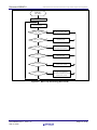
MCU Low power consumption processing
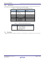
MCU low power consumption processing transitions the MCU to low-power mode when the following conditions are
met:
Table 3-3 Conditions for Transition to Low-Power Mode
VBUS
Transition Condition
USB State
Transition Status
OFF
-
Software standby mode
ON
ON
Suspend Configured
Other than Suspend Configured
Sleep mode
Normal mode (program running)
a) When the device is detached (VBUSOFF), the APL transtions theMCU to software standby mode. Note that
recovery from software standby mode occurs when the RSK boardattaches to the USB host, causing a
transition to normal mode.
b) When the HID device is suspended, the APL transitions the MCU to sleep mode. Note that recovery from sleep
mode occurs when a Resume signal is transmitted by the USB host, causing a transition to normal mode.
R01AN2664EJ0111
Sep 30, 2015
Rev.1.11
Page 15 of 20
Renesas USB MCU
USB Peripheral Human Interface Devices Class Driver Using Firmware Integration Technology Modules
MCU Low power
consumption processing
(hid_low_power_control)
Acquisition USB device
information
USB device information
= USB suspend
= VBUS OFF
Change MCU to the
software standby mode
≠ VBUS OFF
&& USB suspend
Change MCU to Sleep
mode
End
Figure 3-4 Flowchart of MCU Low Power Consumption Processsing
3.3
Switch
3.3.1
Switch specification
The specifications of the switches used in mouse mode and keyboard mode are listed below. The switches on the RSK
are not used in echo mode.
Note that the application program does not recognize a switch press as having occurred when the switch is only pressed
down. The combination of a switch press and release is recognized as a switch press.
1)
2)
Mouse mode
Switch Number
Operation
Switch1(SW1)
Switch2(SW2)
Switch3(SW3)
Left click
Reports motion data for mouse up/down direction.
Reports motion data for mouse right/left direction.
Keyboard mode
Switch Number
Switch2(SW2)
Switch3(SW3)
(Note1)
(Note2)
Operation
One of the key codes for characters “a” to “z” or “Enter” is reported to the
host each time SW is pressed.
One of the key codes for “1” to “9” and “0” or “Enter” is notified to the host
each time SW is pressed.
Movement data is generated when a switch is pressed and held, and the data is reported to the host.
Data reporting stops when the switch is released. Pressing the switch again switches the movement
direction, and movement data reporting continues.
When switches 2 and 3 are both unpressed, in keyboard mode NULL data is transferred to the USB
host, and in mouse mode no data is transferred to the USB host.
R01AN2664EJ0111
Sep 30, 2015
Rev.1.11
Page 16 of 20
Renesas USB MCU
3.3.2
USB Peripheral Human Interface Devices Class Driver Using Firmware Integration Technology Modules
Data Format
The table below shows the transmit report format used for sending data to and from USB Host. These data formats are
set in conjunction with the HID report descriptor contents notified to USB Host.
Table 3-4
offset
Data Formats Used when Notifying the Host
Mouse Mode
(3Bytes)
b0:Button 1
b1:Button 2
b2:Reserved
X displacement
Y displacement
0
1
2
3
4
5
6
7
Table 3-5
offset (byte)
0
3.4
Keyboard Mode
(8Bytes)
Modifier keys
Reserved
Keycode 1
Keycode 2
Keycode 3
Keycode 4
Keycode 5
Keycode 6
Keyboard OUTPUT Report format
Value
b0:LED 0 (NumLock)
b1:LED 1 (CapsLock)
b2:LED 2 (ScrollLock)
b3:LED 3 (Compose)
0: OFF, 1: ON
Descriptor
The PHID’s descriptor information is contained in r_usb_phid_descriptor.c. Also, please be sure to use your vendor
ID.
R01AN2664EJ0111
Sep 30, 2015
Rev.1.11
Page 17 of 20
Renesas USB MCU
4.
USB Peripheral Human Interface Devices Class Driver Using Firmware Integration Technology Modules
Class Request
Table 4-1 shows the class requests supported by PHID.
Table 4-1
Request
Get Report
Set Report
Get Idle
Set Idle
Get Protocol
Set Protocol
Get Report Descriptor
Get HID Descriptor
R01AN2664EJ0111
Sep 30, 2015
Rev.1.11
Supported Basic Requests and HID Class Requests
Code
0x01
0x09
0x02
0x0A
0x03
0x0B
Standard
Standard
Description
Sends a report to the USB Host
Receives a report from the USB Host
Sends a duration (time) to the USB Host
Receives a duration (time) from the USB Host
Sends a protocol to the USB Host
Receives a protocol from the USB Host
Sends a report descriptor to the USB Host
Sends an HID descriptor to the USB Host
Supported
YES
YES
YES
YES
NO
NO
YES
YES
Page 18 of 20
Renesas USB MCU
5.
USB Peripheral Human Interface Devices Class Driver Using Firmware Integration Technology Modules
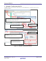
Using the e2 studio project with CS+
The PHID contains a project only for e2 studio. When you use the PHID with CS+, import the project to CS+ by
following procedures.
Launch CS+ and click “Start”.
Select [Open Exsisting e2studio/CS/High-performance Embedded
Workshop/PM+ project] in Start menu.
Select the file with the extension
[.rcpc] and click Open button.
Select [project file for
e2studio]
Select the device used in
the project.
Select the used project
e.g. Sample
The project name depends on the AN.
Select Project type, and specify the
project name and its location.
Click OK button if they are OK.
Figure 5-1
R01AN2664EJ0111
Sep 30, 2015
Rev.1.11
Using the e2 studio project with CS+
Page 19 of 20
Renesas USB MCU
USB Peripheral Human Interface Devices Class Driver Using Firmware Integration Technology Modules
Website and Support
Renesas Electronics Website
http://www.renesas.com/
Inquiries
http://www.renesas.com/inquiry/
All trademarks and registered trademarks are the property of their respective owners.
R01AN2664EJ0111
Sep 30, 2015
Rev.1.11
Page 20 of 20
Revision Record
Rev.
1.11
Date
Sep 30, 2015
Description
Page
Summary
—
First Edition Issued.
A-1
General Precautions in the Handling of MPU/MCU Products
The following usage notes are applicable to all MPU/MCU products from Renesas. For detailed usage notes on the
products covered by this document, refer to the relevant sections of the document as well as any technical updates that
have been issued for the products.
1. Handling of Unused Pins
Handle unused pins in accordance with the directions given under Handling of Unused Pins in the
manual.
The input pins of CMOS products are generally in the high-impedance state. In operation with an
unused pin in the open-circuit state, extra electromagnetic noise is induced in the vicinity of LSI, an
associated shoot-through current flows internally, and malfunctions occur due to the false
recognition of the pin state as an input signal become possible. Unused pins should be handled as
described under Handling of Unused Pins in the manual.
2. Processing at Power-on
The state of the product is undefined at the moment when power is supplied.
The states of internal circuits in the LSI are indeterminate and the states of register settings and
pins are undefined at the moment when power is supplied.
In a finished product where the reset signal is applied to the external reset pin, the states of pins
are not guaranteed from the moment when power is supplied until the reset process is completed.
In a similar way, the states of pins in a product that is reset by an on-chip power-on reset function
are not guaranteed from the moment when power is supplied until the power reaches the level at
which resetting has been specified.
3. Prohibition of Access to Reserved Addresses
Access to reserved addresses is prohibited.
The reserved addresses are provided for the possible future expansion of functions. Do not access
these addresses; the correct operation of LSI is not guaranteed if they are accessed.
4. Clock Signals
After applying a reset, only release the reset line after the operating clock signal has become stable.
When switching the clock signal during program execution, wait until the target clock signal has
stabilized.
When the clock signal is generated with an external resonator (or from an external oscillator)
during a reset, ensure that the reset line is only released after full stabilization of the clock signal.
Moreover, when switching to a clock signal produced with an external resonator (or by an external
oscillator) while program execution is in progress, wait until the target clock signal is stable.
5. Differences between Products
Before changing from one product to another, i.e. to a product with a different part number, confirm
that the change will not lead to problems.
The characteristics of an MPU or MCU in the same group but having a different part number may
differ in terms of the internal memory capacity, layout pattern, and other factors, which can affect
the ranges of electrical characteristics, such as characteristic values, operating margins, immunity
to noise, and amount of radiated noise. When changing to a product with a different part number,
implement a system-evaluation test for the given product.
Notice
1.
Descriptions of circuits, software and other related information in this document are provided only to illustrate the operation of semiconductor products and application examples. You are fully responsible for
the incorporation of these circuits, software, and information in the design of your equipment. Renesas Electronics assumes no responsibility for any losses incurred by you or third parties arising from the
use of these circuits, software, or information.
2.
Renesas Electronics has used reasonable care in preparing the information included in this document, but Renesas Electronics does not warrant that such information is error free. Renesas Electronics
3.
Renesas Electronics does not assume any liability for infringement of patents, copyrights, or other intellectual property rights of third parties by or arising from the use of Renesas Electronics products or
assumes no liability whatsoever for any damages incurred by you resulting from errors in or omissions from the information included herein.
technical information described in this document. No license, express, implied or otherwise, is granted hereby under any patents, copyrights or other intellectual property rights of Renesas Electronics or
others.
4.
You should not alter, modify, copy, or otherwise misappropriate any Renesas Electronics product, whether in whole or in part. Renesas Electronics assumes no responsibility for any losses incurred by you or
5.
Renesas Electronics products are classified according to the following two quality grades: "Standard" and "High Quality". The recommended applications for each Renesas Electronics product depends on
third parties arising from such alteration, modification, copy or otherwise misappropriation of Renesas Electronics product.
the product's quality grade, as indicated below.
"Standard": Computers; office equipment; communications equipment; test and measurement equipment; audio and visual equipment; home electronic appliances; machine tools; personal electronic
equipment; and industrial robots etc.
"High Quality": Transportation equipment (automobiles, trains, ships, etc.); traffic control systems; anti-disaster systems; anti-crime systems; and safety equipment etc.
Renesas Electronics products are neither intended nor authorized for use in products or systems that may pose a direct threat to human life or bodily injury (artificial life support devices or systems, surgical
implantations etc.), or may cause serious property damages (nuclear reactor control systems, military equipment etc.). You must check the quality grade of each Renesas Electronics product before using it
in a particular application. You may not use any Renesas Electronics product for any application for which it is not intended. Renesas Electronics shall not be in any way liable for any damages or losses
incurred by you or third parties arising from the use of any Renesas Electronics product for which the product is not intended by Renesas Electronics.
6.
You should use the Renesas Electronics products described in this document within the range specified by Renesas Electronics, especially with respect to the maximum rating, operating supply voltage
range, movement power voltage range, heat radiation characteristics, installation and other product characteristics. Renesas Electronics shall have no liability for malfunctions or damages arising out of the
use of Renesas Electronics products beyond such specified ranges.
7.
Although Renesas Electronics endeavors to improve the quality and reliability of its products, semiconductor products have specific characteristics such as the occurrence of failure at a certain rate and
malfunctions under certain use conditions. Further, Renesas Electronics products are not subject to radiation resistance design. Please be sure to implement safety measures to guard them against the
possibility of physical injury, and injury or damage caused by fire in the event of the failure of a Renesas Electronics product, such as safety design for hardware and software including but not limited to
redundancy, fire control and malfunction prevention, appropriate treatment for aging degradation or any other appropriate measures. Because the evaluation of microcomputer software alone is very difficult,
please evaluate the safety of the final products or systems manufactured by you.
8.
Please contact a Renesas Electronics sales office for details as to environmental matters such as the environmental compatibility of each Renesas Electronics product. Please use Renesas Electronics
products in compliance with all applicable laws and regulations that regulate the inclusion or use of controlled substances, including without limitation, the EU RoHS Directive. Renesas Electronics assumes
no liability for damages or losses occurring as a result of your noncompliance with applicable laws and regulations.
9.
Renesas Electronics products and technology may not be used for or incorporated into any products or systems whose manufacture, use, or sale is prohibited under any applicable domestic or foreign laws or
regulations. You should not use Renesas Electronics products or technology described in this document for any purpose relating to military applications or use by the military, including but not limited to the
development of weapons of mass destruction. When exporting the Renesas Electronics products or technology described in this document, you should comply with the applicable export control laws and
regulations and follow the procedures required by such laws and regulations.
10. It is the responsibility of the buyer or distributor of Renesas Electronics products, who distributes, disposes of, or otherwise places the product with a third party, to notify such third party in advance of the
contents and conditions set forth in this document, Renesas Electronics assumes no responsibility for any losses incurred by you or third parties as a result of unauthorized use of Renesas Electronics
products.
11. This document may not be reproduced or duplicated in any form, in whole or in part, without prior written consent of Renesas Electronics.
12. Please contact a Renesas Electronics sales office if you have any questions regarding the information contained in this document or Renesas Electronics products, or if you have any other inquiries.
(Note 1)
"Renesas Electronics" as used in this document means Renesas Electronics Corporation and also includes its majority-owned subsidiaries.
(Note 2)
"Renesas Electronics product(s)" means any product developed or manufactured by or for Renesas Electronics.
http://www.renesas.com
SALES OFFICES
Refer to "http://www.renesas.com/" for the latest and detailed information.
Renesas Electronics America Inc.
2801 Scott Boulevard Santa Clara, CA 95050-2549, U.S.A.
Tel: +1-408-588-6000, Fax: +1-408-588-6130
Renesas Electronics Canada Limited
9251 Yonge Street, Suite 8309 Richmond Hill, Ontario Canada L4C 9T3
Tel: +1-905-237-2004
Renesas Electronics Europe Limited
Dukes Meadow, Millboard Road, Bourne End, Buckinghamshire, SL8 5FH, U.K
Tel: +44-1628-585-100, Fax: +44-1628-585-900
Renesas Electronics Europe GmbH
Arcadiastrasse 10, 40472 Düsseldorf, Germany
Tel: +49-211-6503-0, Fax: +49-211-6503-1327
Renesas Electronics (China) Co., Ltd.
Room 1709, Quantum Plaza, No.27 ZhiChunLu Haidian District, Beijing 100191, P.R.China
Tel: +86-10-8235-1155, Fax: +86-10-8235-7679
Renesas Electronics (Shanghai) Co., Ltd.
Unit 301, Tower A, Central Towers, 555 Langao Road, Putuo District, Shanghai, P. R. China 200333
Tel: +86-21-2226-0888, Fax: +86-21-2226-0999
Renesas Electronics Hong Kong Limited
Unit 1601-1611, 16/F., Tower 2, Grand Century Place, 193 Prince Edward Road West, Mongkok, Kowloon, Hong Kong
Tel: +852-2265-6688, Fax: +852 2886-9022
Renesas Electronics Taiwan Co., Ltd.
13F, No. 363, Fu Shing North Road, Taipei 10543, Taiwan
Tel: +886-2-8175-9600, Fax: +886 2-8175-9670
Renesas Electronics Singapore Pte. Ltd.
80 Bendemeer Road, Unit #06-02 Hyflux Innovation Centre, Singapore 339949
Tel: +65-6213-0200, Fax: +65-6213-0300
Renesas Electronics Malaysia Sdn.Bhd.
Unit 1207, Block B, Menara Amcorp, Amcorp Trade Centre, No. 18, Jln Persiaran Barat, 46050 Petaling Jaya, Selangor Darul Ehsan, Malaysia
Tel: +60-3-7955-9390, Fax: +60-3-7955-9510
Renesas Electronics India Pvt. Ltd.
No.777C, 100 Feet Road, HALII Stage, Indiranagar, Bangalore, India
Tel: +91-80-67208700, Fax: +91-80-67208777
Renesas Electronics Korea Co., Ltd.
12F., 234 Teheran-ro, Gangnam-Gu, Seoul, 135-080, Korea
Tel: +82-2-558-3737, Fax: +82-2-558-5141
© 2015 Renesas Electronics Corporation. All rights reserved.
Colophon 5.0