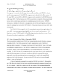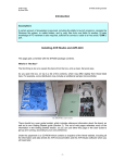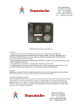
1
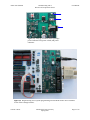
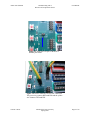
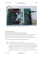
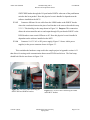
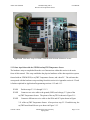
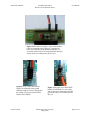
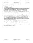
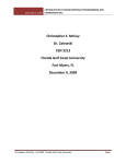
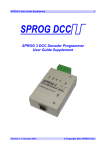
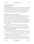
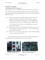
Atmel AVR STK500
Communicating with a
Host PC and Temperature Sensor
User Manual
2. Hardware Connectivity
2.1 Enabling the Board to be Programmed
Programming the target devices installed on the STK500 is called “in-system programming”
(ISP) and is achieved using serial communication between the host PC and master MCU. The
needed physical setup that enables programming the target device that correlates with ISP header
SPROG3 is as follows:
2.1.1
Connect the 6-pin ISP cable from ISP6PIN to SPROG3 (Figure 2.1 shows these
respective source and target 6-pin ISP headers). Make sure there is a proper
correlation between pins when connecting headers (i.e. pin 0 of ISP6PIN should
correlate with pin 0 of SPROG3, pin 1 of ISP6PIN with pin 1 of SPROG3, and so
on). The red edge of the 6-wire and 10-wire cables should help in achieving this
proper pin-to-pin orientation.
2.1.2
Connect the male-end of a serial cable to the RS232 CTRL serial port, which is the
second serial port from the edge as shown in Figure 2.2. Then connect the other end
of the serial cable to the host PC.
2.1.3
Connect a 10-15 V AC or DC power supply (Figure 1.3 shows viable power supplies)
to the power connector shown in Figure 2.3.
This concludes the hardware connectivity that enables the STK500 to be programmed.
The completed board setup should look the same as the setup in Figure 2.4.
Figure 2.1 From bottom to top: 6-pin
ISP headers ISP6PIN and SPROG3.
Vincent A. Rosa
Figure 2.2 From left to right: RS-232 ports
RS232 CTRL and RS232 SPARE.
Florida Gulf Coast University
Spring 2009
Page 1 of 10
Atmel AVR STK500
Communicating with a
Host PC and Temperature Sensor
User Manual
Figure 2.3 From top to bottom at the right edge:
power indicator LED, power switch, and power
connector
Figure 2.4 Required setup for in-system programming on an STK500 with a device installed
in one of the red target sockets.
Vincent A. Rosa
Florida Gulf Coast University
Spring 2009
Page 2 of 10
Atmel AVR STK500
Communicating with a
Host PC and Temperature Sensor
User Manual
2.2 Enabling Serial Communication with an External Device
Although the STK500 User Guide describes the pins dedicated for RS-232 serial communication
as universal asynchronous receiver and transmitter (UART) pins [1], the ATmega8515L
architecture allows for both synchronous and asynchronous receiving and transmitting [4].
Therefore, the pins are more accurately USART (universal synchronous/asynchronous receiver
and transmitter) pins. The ATmega8515(L) Datasheet [4] contains a complete list of the USART
specifications for the ATmega8515 MCU used in this project.
The RS232 SPARE serial port must be used for the board to receive data from or transmit
data to an external device using its USART pins, even if the external target is the same host PC
that is used to program the board. The RS232 CTRL port is dedicated only for programming the
board, and the RS232 SPARE is dedicated for other serial communication such as sending
measurement data to the host. The RXD and TXD pins of the RS232 SPARE header (not port)
shown in Figure 2.5 need to be established both in hardware and in software to enable serial
communication across the RS232 SPARE port. Data are sent via the TXD pin, and data are
received via the RXD pin. The required setup to use the RS232 SPARE port is as follows:
2.2.1
Connect a two-wire cable from the RXD and TXD pins to the PD0 and PD1 pins of
PORTD in this respective order as seen in Figure 2.6. Note: This is the required
setup for using the RS232 SPARE serial port. The STK500 User Manual simply
diagrams this and does not explicitly state that pins PD0 and PD1 of PORTD are
dedicated for enabling USART communication. This is explicitly stated, however, by
the ATmega8515(L) Datasheet [4] in the “Alternate Port Functions” section.
2.2.2
Connect the male-end of a serial cable to the RS232 SPARE serial port shown in
Figure 2.2, and connect the other end of the serial cable to the target device.
2.2.3
Connect a 10-15 V AC or DC power supply (Figure 1.3 shows viable power supplies)
to the power connector shown in Figure 2.3.
This concludes the hardware connectivity that enables serial communication to an
external device. The final setup should look like the setup in Figure 2.7.
Vincent A. Rosa
Florida Gulf Coast University
Spring 2009
Page 3 of 10
Atmel AVR STK500
Communicating with a
Host PC and Temperature Sensor
User Manual
Figure 2.5 RXD and TXD pins of the RS232
SPARE port header.
Figure 2.6 RXD to PD0 and TXD to PD1 connection.
The green wire connects RXD and PD0 and the yellow
wire connects TXD and PD1.
Vincent A. Rosa
Florida Gulf Coast University
Spring 2009
Page 4 of 10
Atmel AVR STK500
Communicating with a
Host PC and Temperature Sensor
User Manual
Figure 2.7 Required setup for external RS-232 serial communication.
2.3 Project Connectivity
2.3.1 Test Program for STK500-to-Host Serial Communication
The purpose for the hardware setup accomplished from this section is to allow the user to be
introduced to in-system programming, on-board communication, and board-to-host
communication. The software that corresponds with this setup is given in Appendix section
A.2.1 and is further explained in Application Programming section 4.1.1.
2.3.1.1
Perform steps 2.1.1, 2.1.2, 2.2.1, and 2.2.2.
2.3.1.2
Connect a 10-wire cable from the SWITCHES header to the PORTA header
where the pins of each header must correlate as follows: pin SW0 connects with pin
PA0, SW1 connects with PA1, SW2 connects with PA2, and this continues so that
GND connects with GND and VTG connects with VTG as shown in Figure 2.8.
Purpose: This connection allows the microcontroller unit to receive input from the
Vincent A. Rosa
Florida Gulf Coast University
Spring 2009
Page 5 of 10
Atmel AVR STK500
Communicating with a
Host PC and Temperature Sensor
User Manual
SWITCHES header through the I/O port header PORTA when one of the push-button
switches has been pushed. How this physical event is handled is dependent on the
software installed on the MCU.
2.3.1.3
Connect a different 10-wire cable from the LEDS header to the PORTC header
where the correlation between the pins of each header is the same as described in step
2.3.1.2. This should give the setup shown in Figure 2.9. Purpose: This connection
allows the microcontroller unit to send output through I/O port header PORTC to the
LEDS header to turn certain LEDs on or off. How this physical event is handled is
dependent on the software installed on the MCU.
2.3.1.4
Connect a 10-15 V AC or DC power supply (Figure 1.3 shows viable power
supplies) to the power connector shown in Figure 2.3.
This concludes the hardware setup used in the sample project in Appendix section A.2.1
that allows for testing serial communication between an STK500 and its host. The final setup
should look like the one shown in Figure 2.10.
Figure 2.8 A 10-wire cable connecting the
SWITCHES and PORTA headers.
Vincent A. Rosa
Figure 2.9 A 10-wire cable connecting the LEDS
and PORTC headers
Florida Gulf Coast University
Spring 2009
Page 6 of 10
Atmel AVR STK500
Communicating with a
Host PC and Temperature Sensor
User Manual
Figure 2.10 A hardware setup for USART communication from the STK500 to its host.
2.3.2 Data Acquisition with the STK500 and myTWI Temperature Sensor
The hardware setup accomplished from the set of instructions within this section is the main
focus of this manual. This setup establishes the physical attributes of the data acquisition system
formed with an STK500 PCB, a myTWI Temperature Sensor, and a host PC. The software that
corresponds with the hardware setup resulting from this section is in Appendix section A.2.2 and
is further explained in Application Programming sections 4.1.2 and 4.1.3.
2.3.2.1
Perform steps 2.3.1.1 through 2.3.1.3.
2.3.2.2
Connect a two-wire cable to the ground (GND) and voltage (5 V) pins of the
myTWI Temperature Sensor. The pinout of the myTWI is shown in Figure 2.11.
2.3.2.3
Connect a different two-wire cable to the SDA and SCL pins shown in Figure
2.11 of the myTWI Temperature Sensor. After previous step 2.3.2.2 and this step, the
myTWI board should be set up as shown in Figure 2.12.
Vincent A. Rosa
Florida Gulf Coast University
Spring 2009
Page 7 of 10
Atmel AVR STK500
2.3.2.4
Communicating with a
Host PC and Temperature Sensor
User Manual
Connect the two-wire cable that is connected to the GND and 5 V pins of the
myTWI to the GND and VTG pins of the PORTE header, respectively. For example,
if the red and black cable is used, have the red wire connecting the voltage pins (5 V
and VTG) and the black wire connecting the ground pins (GND and GND). This
example setup is shown in Figure 2.13.
2.3.2.5
Connect the two-wire cable that is connected to the SDA and SCL pins of the
myTWI to the PE0 and PE1 pins of the PORTE header, respectively. For example, if
the blue and white cable is used, have the blue wire connecting the SDA and PE0 pins
and have the white wire connecting the SCL and PE1 pins. The combined setup from
previous step 2.3.2.5 and this step is shown in Figure 2.14.
This concludes the hardware connectivity used to form a basic data acquisition system
using an STK500 development board and a myTWI Temperature Sensor. The final physical
setup from this section should be equivalent to the one shown in Figure 2.15.
Figure 2.11 Pinout of the myTWI Temperature Sensor.
Vincent A. Rosa
Florida Gulf Coast University
Spring 2009
Page 8 of 10
Atmel AVR STK500
Communicating with a
Host PC and Temperature Sensor
User Manual
Figure 2.12 From left to right: a 2-wire cable with its
red wire connected to the voltage (5 V) pin and its
black wire connected to the ground (GND) pin; a 2wire cable with its blue wire connected to the SDA pin
and its white wire connected to the SCL pin.
Figure 2.13 A 2-wire cable with its
black wire connected to the ground
(GND) pin and its red wire connected to
the voltage (VTG) pin on the PORTE
header of an STK500.
Vincent A. Rosa
Figure 2.14 At the top of the PORTE
header of an STK500: a 2-wire cable
with its blue wire connected to the PE0
pin and its white wire connected to the
PE1 pin.
Florida Gulf Coast University
Spring 2009
Page 9 of 10
Atmel AVR STK500
Communicating with a
Host PC and Temperature Sensor
User Manual
Figure 2.15 A hardware setup for a DAQ system with an STK500 evaluation
board, a myTWI Temperature Sensor, and a host PC.
Vincent A. Rosa
Florida Gulf Coast University
Spring 2009
Page 10 of 10