1
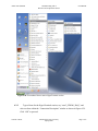
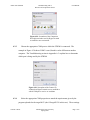
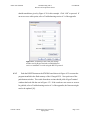
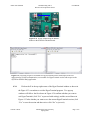
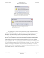
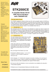
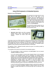
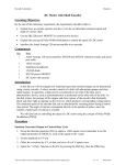
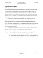
Atmel AVR STK500
Communicating with a
Host PC and Temperature Sensor
User Manual
4. Application Programming
4.3 Executing an Application
The installed application will begin executing right after it is loaded into the target MCU of the
STK500, right after the board is powered on, or right after the RESET button is pushed. The
most important operations performed by an AVR application are typically written within an
infinite loop nested in its main function, which is the case for both sample projects provided in
Appendix section A.2. Therefore, these operations should run continuously while the board is
powered on.
It is imperative to remember that the functionality of the board with respect to its
application software is dependent on the hardware setup (e.g. if PORTA is programmed to
control the switches, then a 10-wire cable must properly connect the PORTA header to the
SWITCHES header). Appendix section A.3, Troubleshooting, addresses how to resolve some of
the common issues encountered that would cause the board to not respond as desired with
respect to the installed application.
The following set of instructions provides how to check whether the sample programs in
Appendix sections A.2.1 and A.2.2.1 are running properly on the STK500 PCB.
4.3.1
Open the HyperTerminal program by going to “Start”, “All Programs”,
“Accessories”, “Communications”, and selecting “HyperTerminal” as seen in Figure
4.28. If this is the first time HyperTerminal is used, enter an area code and follow the
on-screen instructions given by the HyperTerminal program. Click “OK” to proceed.
Vincent A. Rosa
Florida Gulf Coast University
Spring 2009
Page 1 of 6
Atmel AVR STK500
Communicating with a
Host PC and Temperature Sensor
User Manual
Figure 4.28 Screenshot of how to start a HyperTerminal session.
4.3.2
Type a Name for the HyperTerminal session, say “com3_STK500_DAQ”, and
select an Icon within the “Connection Description” window as shown in Figure 4.29.
Click “OK” to proceed.
Vincent A. Rosa
Florida Gulf Coast University
Spring 2009
Page 2 of 6
Atmel AVR STK500
Communicating with a
Host PC and Temperature Sensor
User Manual
Figure 4.29 Screenshot of the Connection
Description window used by HyperTerminal
to establish a new connection.
4.3.3
Choose the appropriate COM port to which the STK500 is connected. The
example in Figure 4.30 shows COM3 is used, but this can be different on another
computer. The Troubleshooting section in Appendix A.3 explains how to determine
which port is being used by the STK500.
Figure 4.30 Screenshot of the Connect To
window that HyperTerminal uses to establish at
which COM port to receive or send data.
4.3.4
Select the appropriate COM properties to match the requirements given by the
program uploaded to the target MCU (the ATmega8515L in this case). These settings
Vincent A. Rosa
Florida Gulf Coast University
Spring 2009
Page 3 of 6
Atmel AVR STK500
Communicating with a
Host PC and Temperature Sensor
User Manual
should match those given by Figure 4.31 for this example. Click “OK” to proceed. If
an error occurs at this point, refer to Troubleshooting section A.3 of the appendix.
Figure 4.31 Screenshot of the COM port settings
window used by HyperTerminal to establish how to
receive or send data via serial using the RS-232 protocol.
4.3.5
Push the RESET button on the STK500 board shown in Figure 4.32 to restart the
program installed in the flash memory of the ATmega8515L. Now push one of the
push-button switches. The results from these actions should yield a HyperTerminal
window that looks like the one in Figure 4.33. If the results are not correct or seem to
be garbled, refer to Troubleshooting section A.3 of the appendix; the firmware might
need to be updated [16].
Vincent A. Rosa
Florida Gulf Coast University
Spring 2009
Page 4 of 6
Atmel AVR STK500
Communicating with a
Host PC and Temperature Sensor
User Manual
Figure 4.32 Picture emphasizing the RESET
button on the STK500 evaluation board.
Figure 4.33 From left to right: a screenshot of a HyperTerminal session with respect to the test
application for USART communication; a screenshot of a HyperTerminal session with respect to the
myTWI-to-STK500 DAQ application.
4.3.6
Click on the X in the top-right corner of the HyperTerminal window as shown in
the Figure 4.33 screenshots to exit the HyperTerminal program. Two pop-up
windows will follow: the first shown in Figure 4.34 confirms whether you want to
exit HyperTerminal (click “Yes” to proceed with exiting), and the second shown in
Figure 4.35 asks whether you want to save the current HyperTerminal session (click
“Yes” to save the session and then exit or click “No” to just exit).
Vincent A. Rosa
Florida Gulf Coast University
Spring 2009
Page 5 of 6
Atmel AVR STK500
Communicating with a
Host PC and Temperature Sensor
User Manual
Figure 4.34 Screenshot of the HyperTerminal
pop-up window that appears when an attempt has
been made to exit a HyperTerminal session.
Figure 4.35 Screenshot of the HyperTerminal pop-up
window that appears when an exiting an unsaved
HyperTerminal session.
This concludes how to execute the test application for USART communication and the
myTWI-to-STK500 DAQ application. Appendix section A.3, Troubleshooting, covers some of
the common errors that arise while carrying out the instructions provided in this section.
Try editing the code used in this section to have one push-button switch correspond to
one LED (say SW3 with LED3) where the LED will turn on or off when this button is pushed.
Then try adding some code that will send a message to the host via USART when a different
button is pushed, say SW7. It is important to know that PA3 controls SW3 and that PA7 controls
SW7 since PORTA is connected to the SWITCHES header. Similarly, PC3 controls LED3 since
PORTC is connected to the LEDS header. Also note from the provided sample programs in
Appendix section A.2 that a carriage return (“\r”) must be sent when starting a new line (“\n”) in
HyperTerminal; otherwise, the data sent will be skewed.
Vincent A. Rosa
Florida Gulf Coast University
Spring 2009
Page 6 of 6